new web: http://bdml.stanford.edu/pmwiki
TWiki > RisePrivate Web>PrivateRiSE > NewProposals>FootActuation (10 May 2006, MarkCutkosky)
Foot Actuation
New stuff:
Movies showing new prototype:
- Prototype_movie1_divx.AVI: Movie1 of foot actuator prototype
- Prototype_movie2_divx.AVI: Movie2 of foot actuator prototype
Other comments:
There are a few changes I will make to the design as posted previously. Here is a brief list of changes that will be made. Updated- Change cam angle so it has a longer shallow-slope part so it can wedge foot down better, also make the steep part shorter and steeper.
- Make bump in
FootAttachment piece (piece on the hinge that goes up and down) bigger to improve cam wedging action
- Cam needs groove all the way around to permit full rotation
- Cam should occupy more of a full circle (probably 330 degrees) rather than the ~240 degrees it is now
- Might have to make changes in how the piece that rotates up and down (
FootAttachment in the solidworks files) is attached to its hinge
- Put screw hole near the running foot that holds cam cover down (currently it is primarily held by the two screws on one side)
- Make cam cover go all the way down to the flat plate on the bottom, rather than having a ~3mm gap as it currently has
- Strengthen bottom plate by adding a ridge along the length of it (on the bottom)
- Check height of screw holes in hinge, and also check tolerances on cam and cam cover. How much friction will aluminum have?
- Increase spring stiffness and include a preload.
Previous stuff:
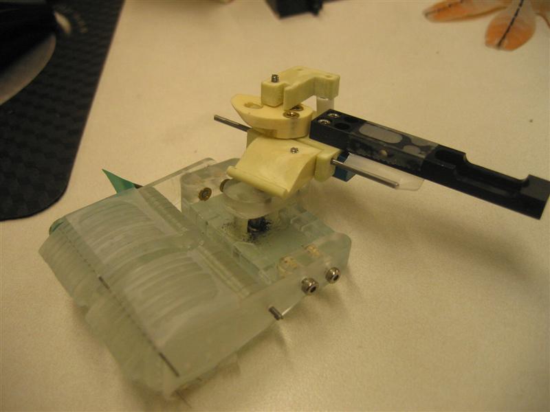
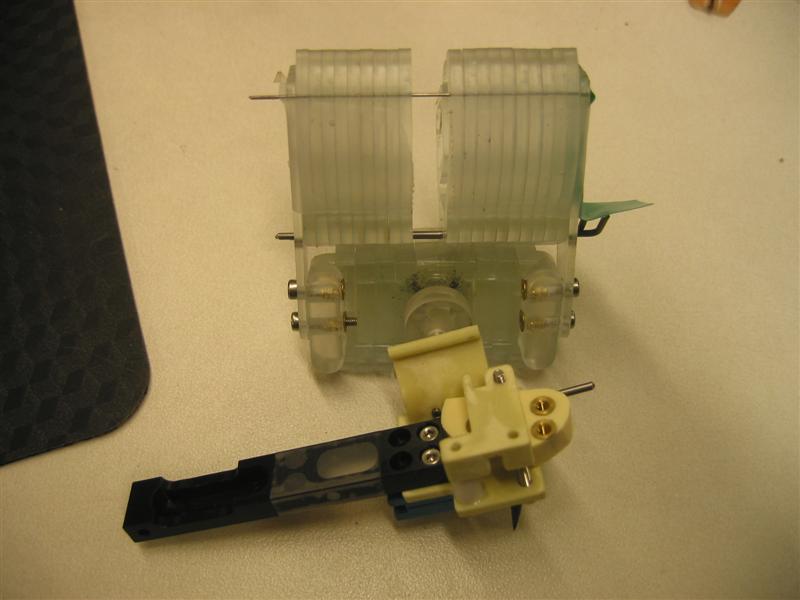
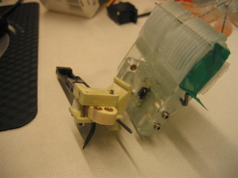
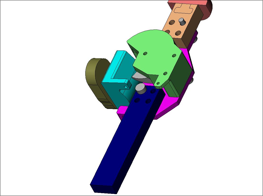
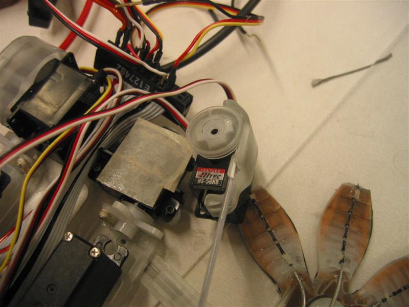
The general idea is to have a servo mounted on the main body ofPictures of a crude prototype with cam and foot and dactyl.
Dimensions of cam in prototype are the same as in- Prototype - cam engaged, foot down:
- Prototype - foot up, back view:
- Prototype - view from end of foot showing dactyl:
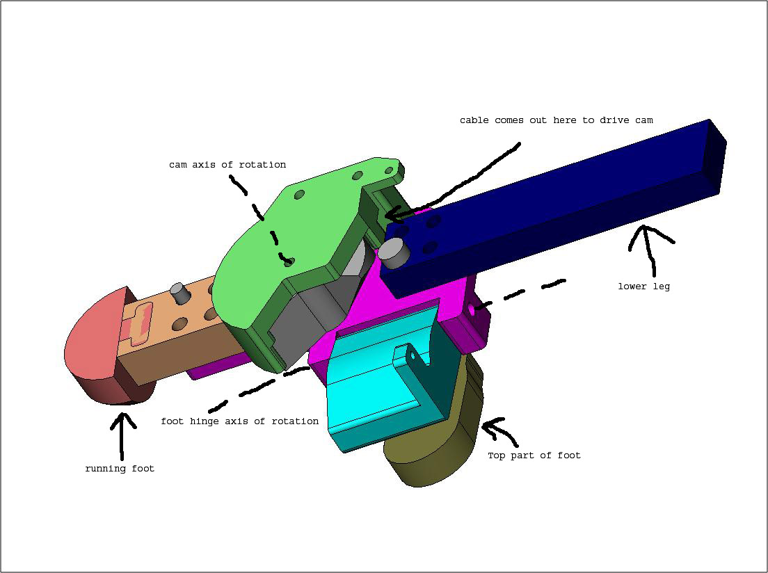
Pictures of SolidWorks model
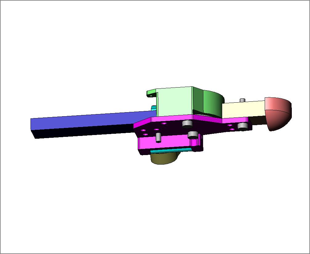
The - Overview of Foot Actuation idea:
- Overview showing spring and foot:
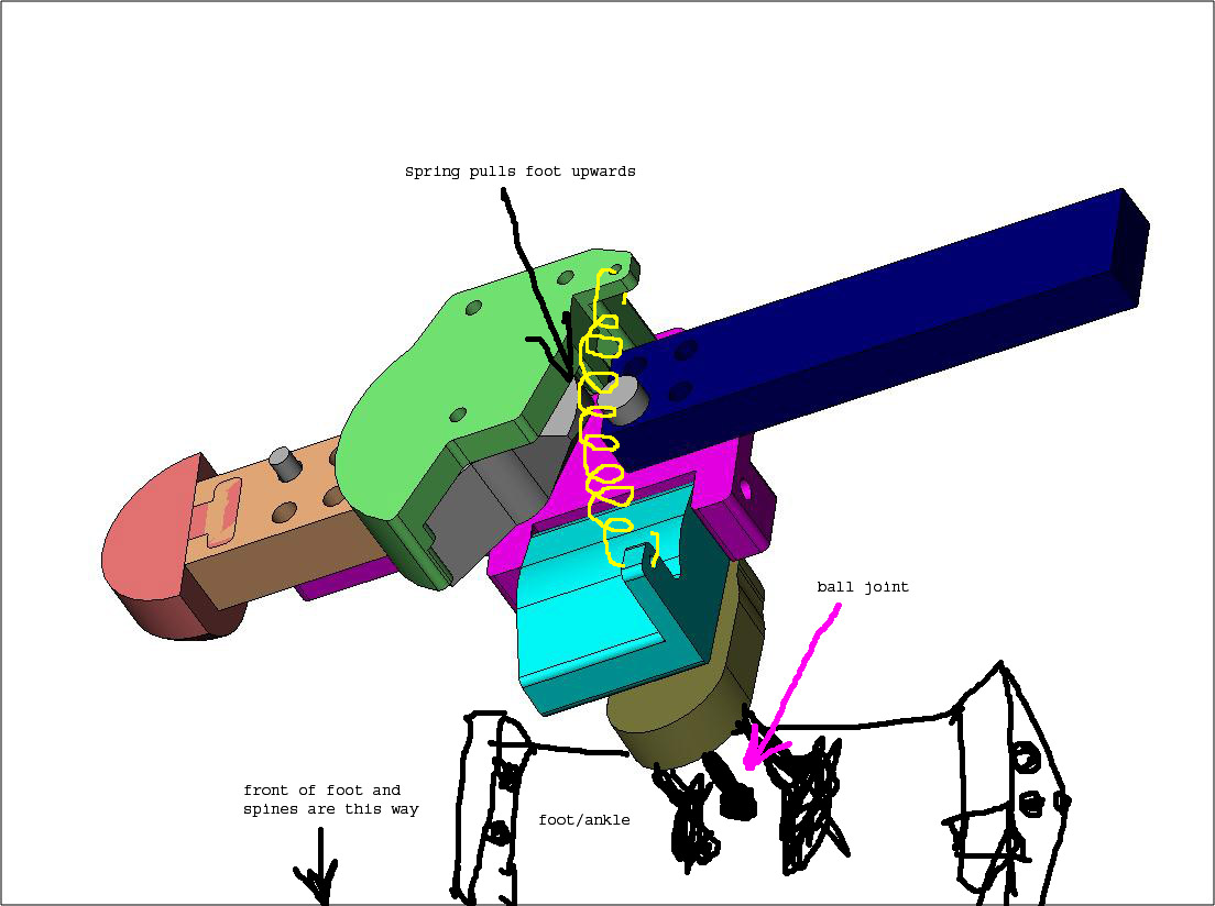
- Top view looking from back of foot (looking from tail):
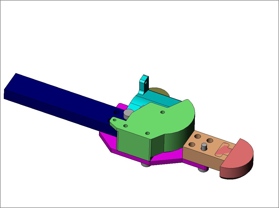
- Bottom view:
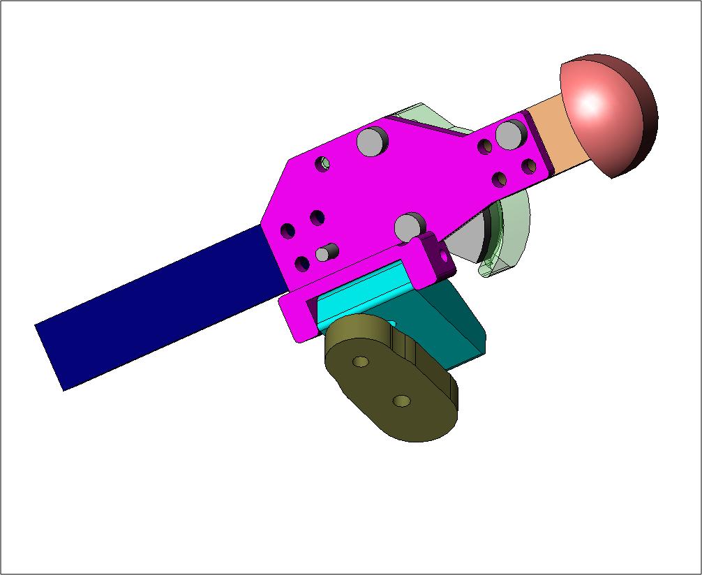
- Cam pushes foot down:
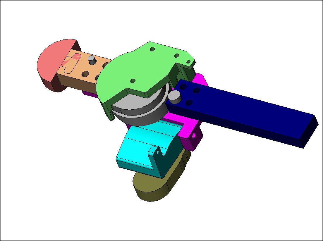
- Cam is retracted, foot in the "up" position:
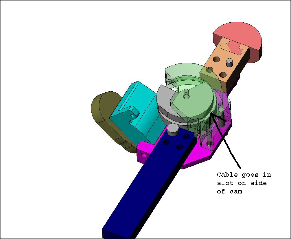
- Transparent cam cover showing cam and slot for cable:
- Side view looking from the tail (back of foot):
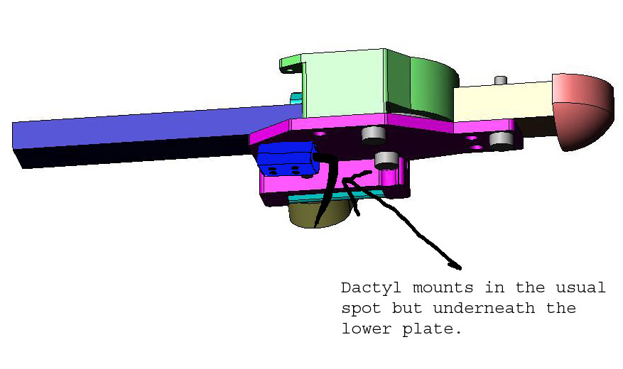
- Side view showing where dactyl goes: Note that in this drawing the dactyl is smaller than it will be in real life (see pictures at top of this web page)
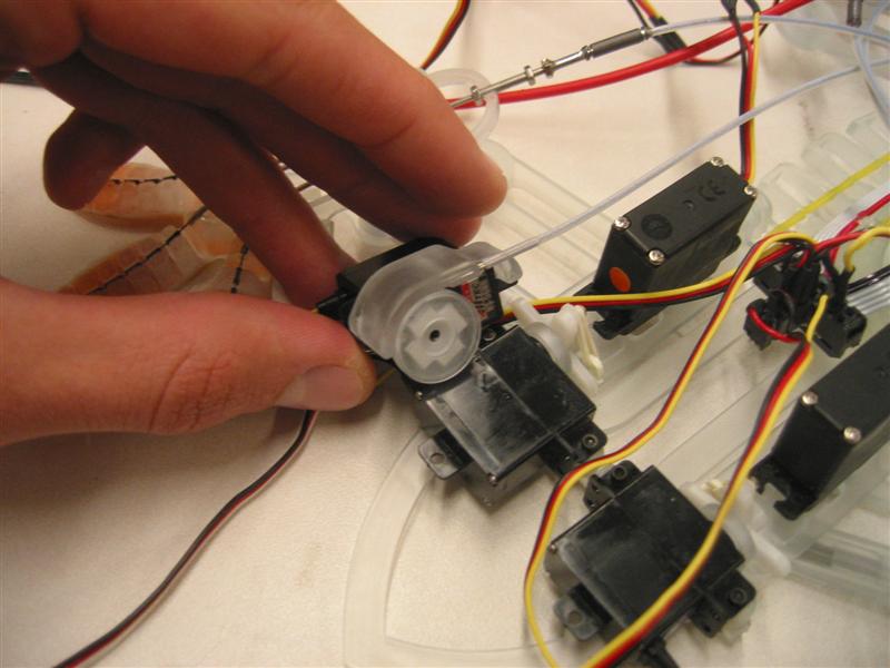
Pictures of servos with cable drive, currently on Main.StickyBot
The cable attachment on the Foot Actuator will be very similar to the mechanism shown in the pictures below, with the cable going between the cam and the cam cover in a little groove/slot. The cable will come out of the cam cover and go right into a sheath, a little tube that is glued to the cam cover.
In addition, the servos on the main body of - Servo with cable drive attachment:
- Another servo with cable drive attachment:
Ideas, requests, problems regarding TWiki? Send feedback