new web: http://bdml.stanford.edu/pmwiki
TWiki > Rise Web>TestTrackAccelerometerSetup (23 Jun 2004, AlanAsbeck)
-- AlanAsbeck - 23 Jun 2004
This page explains how to setup the accelerometer for use with Test Track experiments.
1. Get power supply, accelerometer from drawer marked "Alan's Accelerometer stuff"
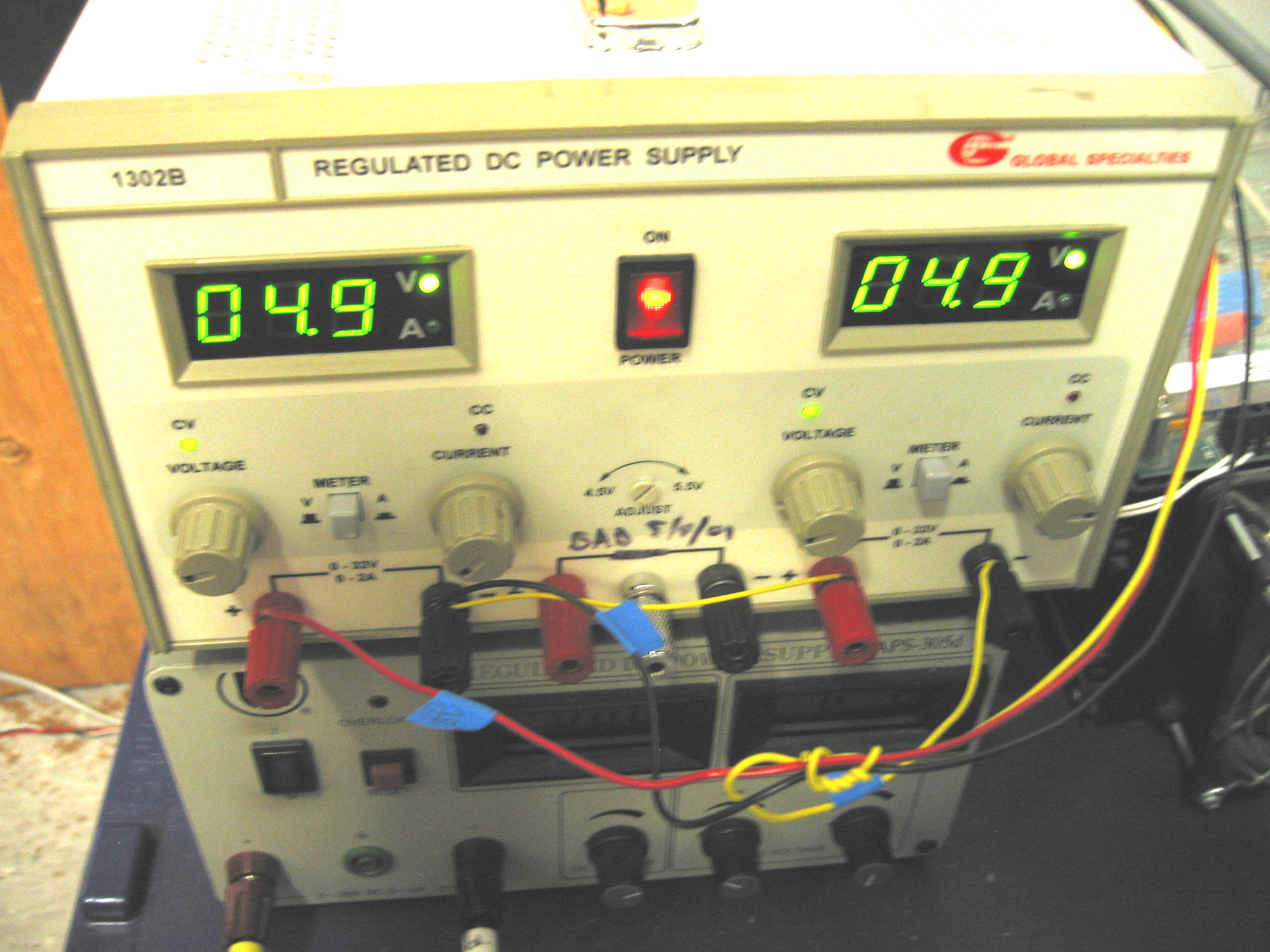
2. Plug in the power supply to the wall. Before attaching wires to the power supply, turn it on and check the voltages. Both LED displays should read 4.9V. (The nominal voltage is 5V, but the power supply fluctuates a little, so I think it is best to keep it at 4.9V).
3. Take the red, black, yellow wires attached to the climbing wall (probably coiled up next to the circuit board) and attach them to the power supply using the little tighten-down screws. The power supply should be hooked up like this:
O = terminal on the front of the power supply
RW = red wire
BW = black wire
YW = yellow wire
YSW = yellow short wire, just going between the two halves of the power supply.
RW O----- +4.9V -----O BW,YSW.......YSW O----- +4.9V -----O YW
(see bottom of page for full-sized image)
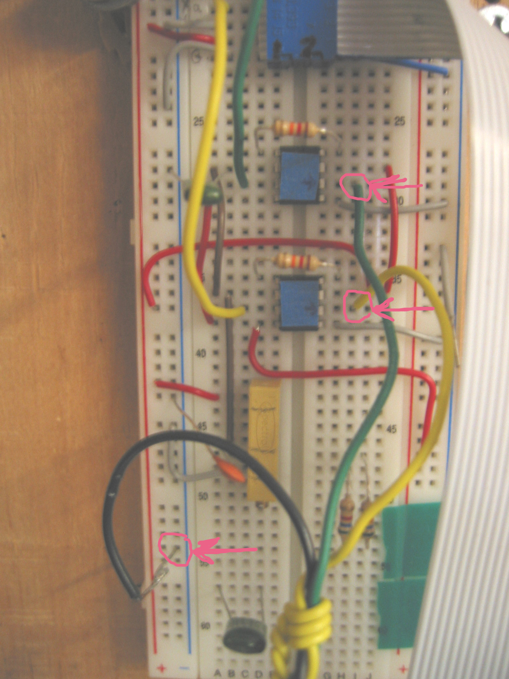
 4. Connect the wires coming from the labview breakout box to the breadboard. The rows that the wires should go on are indicated by little arrows taped to the top of the chips. Put the green wire next to the chip that has a green input wire, and the yellow wire next to the chip that has a yellow input wire.
Breadboard hookup: (see bottom of page for full-sized image)
4. Connect the wires coming from the labview breakout box to the breadboard. The rows that the wires should go on are indicated by little arrows taped to the top of the chips. Put the green wire next to the chip that has a green input wire, and the yellow wire next to the chip that has a yellow input wire.
Breadboard hookup: (see bottom of page for full-sized image)
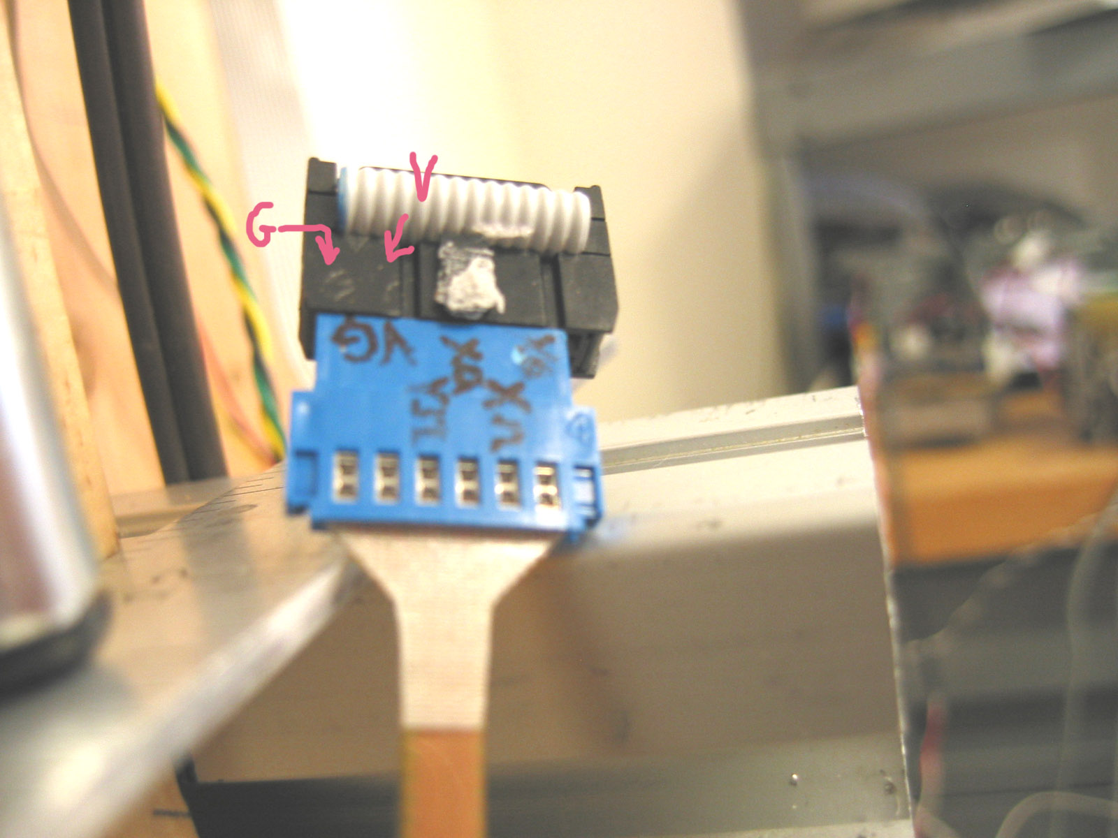
 5. Plug in the accelerometer to the ribbon cable coming out of the breadboard. The accelerometer is labeled with "GV" on one side, and the ribbon cable connector has a little "GV" engraved on one side of it. Line up the accelerometer GV with the ribbon cable GV. The ribbon cable connector has two rows--plug the accelerometer into the row that is the one right next to the engraved GV.
Front view: (see bottom of page for full-sized image)
5. Plug in the accelerometer to the ribbon cable coming out of the breadboard. The accelerometer is labeled with "GV" on one side, and the ribbon cable connector has a little "GV" engraved on one side of it. Line up the accelerometer GV with the ribbon cable GV. The ribbon cable connector has two rows--plug the accelerometer into the row that is the one right next to the engraved GV.
Front view: (see bottom of page for full-sized image)
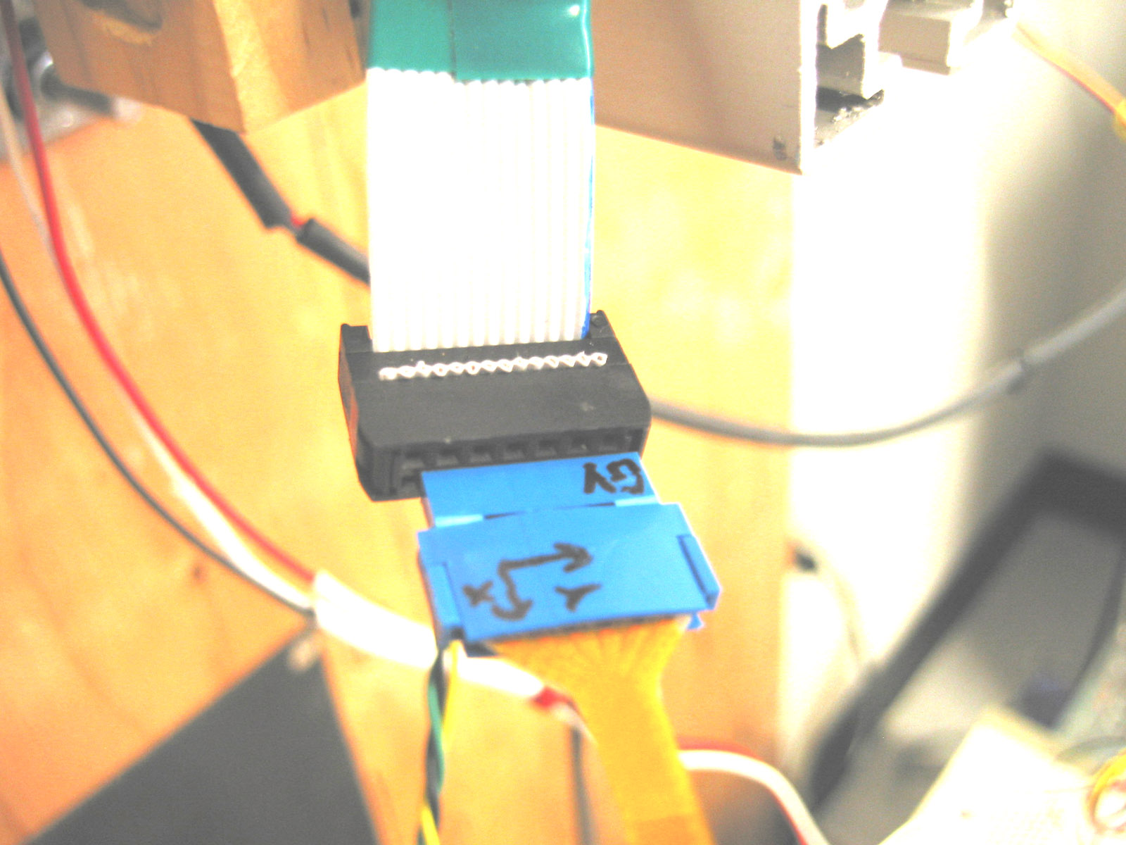
 Back view: (see bottom of page for full-sized image)
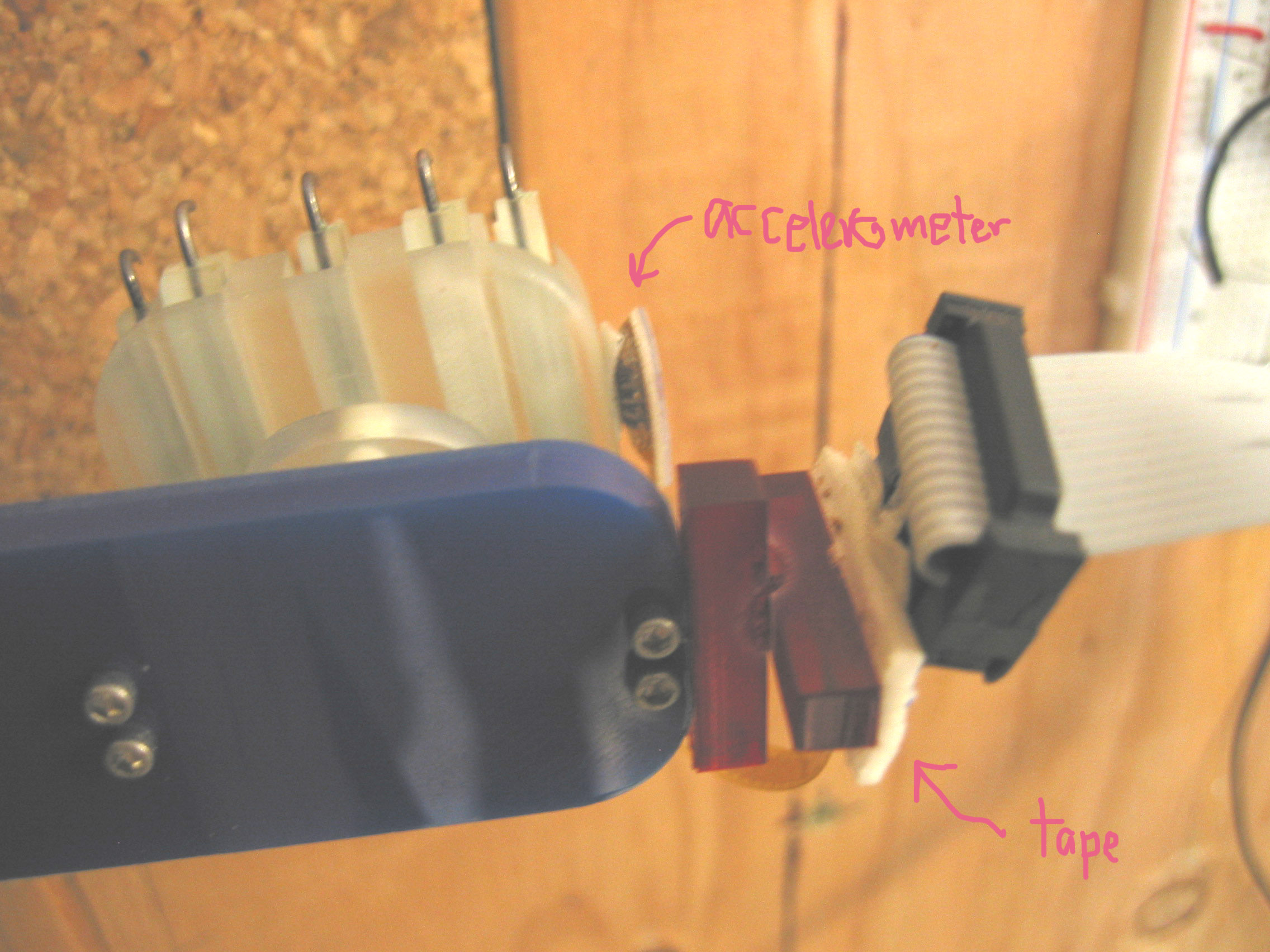
 6. Tape the accelerometer to the foot. I cut off a small piece of carpet tape that is of an area twice the area of the top of the accelerometer chip. Then, I fold it in half so that the sticky part is inside, and the paper backing is outside. Then, peel off half the paper backing and stick the tape to the top of the accelerometer chip. Peel off the rest of the paper backing and stick the accelerometer to the foot.
7. Tape the cable to the foot. I use double-sided foam tape. Tape the ribbon cable connector or blue accelerometer connector to the red structure on the side of the test leg. Put it in such a way that there is minimal strain on the accelerometer flex circuit cable.
How accelerometer and cable tape to foot: (see bottom of page for full-sized image)
6. Tape the accelerometer to the foot. I cut off a small piece of carpet tape that is of an area twice the area of the top of the accelerometer chip. Then, I fold it in half so that the sticky part is inside, and the paper backing is outside. Then, peel off half the paper backing and stick the tape to the top of the accelerometer chip. Peel off the rest of the paper backing and stick the accelerometer to the foot.
7. Tape the cable to the foot. I use double-sided foam tape. Tape the ribbon cable connector or blue accelerometer connector to the red structure on the side of the test leg. Put it in such a way that there is minimal strain on the accelerometer flex circuit cable.
How accelerometer and cable tape to foot: (see bottom of page for full-sized image)
4. Connect the wires coming from the labview breakout box to the breadboard. The rows that the wires should go on are indicated by little arrows taped to the top of the chips. Put the green wire next to the chip that has a green input wire, and the yellow wire next to the chip that has a yellow input wire.
Breadboard hookup: (see bottom of page for full-sized image)
5. Plug in the accelerometer to the ribbon cable coming out of the breadboard. The accelerometer is labeled with "GV" on one side, and the ribbon cable connector has a little "GV" engraved on one side of it. Line up the accelerometer GV with the ribbon cable GV. The ribbon cable connector has two rows--plug the accelerometer into the row that is the one right next to the engraved GV.
Front view: (see bottom of page for full-sized image)
Back view: (see bottom of page for full-sized image)
6. Tape the accelerometer to the foot. I cut off a small piece of carpet tape that is of an area twice the area of the top of the accelerometer chip. Then, I fold it in half so that the sticky part is inside, and the paper backing is outside. Then, peel off half the paper backing and stick the tape to the top of the accelerometer chip. Peel off the rest of the paper backing and stick the accelerometer to the foot.
7. Tape the cable to the foot. I use double-sided foam tape. Tape the ribbon cable connector or blue accelerometer connector to the red structure on the side of the test leg. Put it in such a way that there is minimal strain on the accelerometer flex circuit cable.
How accelerometer and cable tape to foot: (see bottom of page for full-sized image)
Ideas, requests, problems regarding TWiki? Send feedback