new web: http://bdml.stanford.edu/pmwiki
TWiki > Rise Web>SprawlTurning>SprawlTurnLegUseTesting (13 Aug 2003, AMcClung? )
Leg Use Testing
Experimental Results (Attachments)- LegTurnNotes2.doc - indentifies key attributes for each test group and ranks the group turning methods (ADAMS sim and Overhead (OH) robot testing
- maxsortboth2.xls - contains the top 4 turn setups for each testing group, and statistics for leg use in these top 4 setups
- legs_turning2.doc - cryptic description of the tests to be performed and the motivation (please ask me for clarification if it seems crazy)
- Include better description of experiments (?)
- Include some charts of the data (?)
Front legs seem to have major control over the gait. This is commonly the leg that has the most distinct function of the 3 contralateral leg pairs. The middle legs are used to support and also thrust the body. The rear are mainly used to thrust the body forward. The front leg has been shown (thru Jclark?s sims) to greatly influence the speed and stability of the robot. It alone can cause speed changes and instability. It is generally the odd leg out in terms of its use and longitudinal thrust direction. Because of these observations, it is the single most important leg in maneuvers and body configuration control (pitch and roll).
(Is this behaving as a rear wheel drive car with front axle steering? Most of the thrust is coming from mid and rear, while the front leg can be used to steer.) The front and rear legs combined seem to play a strong role in control of the robot motion. The front and rear legs can both create the changes necessary to produce maneuvers in the yaw (horizontal), pitch (sagittal) and roll (frontal) planes maneuver analyses previously listed. These two legs can cause a change in force location and magnitude relative to the COM. These changes create turning moments about the COM (H-plane
(Test this idea on robot) <DCi-20%?, DCo-20%?>
- new LT leg positions cause interference
- above strategy (with LM adjusted for interference) does not turn well
- lower velocity and slower turning, body rolls, but also tends to drag
- RF change may cause the gait to be unstable (nosedive on right)
- minus RF position change creates stability, but still slow
- minus RM DC change (also RF LA) turns a bit better
- same DC (35%) throughout still seems to be best turn (LA ips)
- RM+ and LM- DC changes (separately and combined) both produce poor, non-period 1 turns
- (Might try more extreme DC values)
It is clear from the leg testing for turning that changing more than one leg will produce a better turn than just using a singular leg, if these legs are changed properly. Thus the method for changing these legs should be further investigated. Using more legs adds more direct control of the turning moment (yaw), body pitch and body roll. (This trend may reach a plateau that tapers off as more than 3 legs are used.) From experiments, it is apparent that changing leg properties on the same side of the body are more effective than changing contralaterally or diagonally leg properties. It is further been shown that when changing these ipsilateral legs, changing them in the same direction (in particular moving the foot placement of multiple legs forward, or increasing the DC on two legs) is more effective than changing the legs in different directions (an increase and a decrease). The nominal settings allow the robot to run very stably and are the results of several rounds of performance analysis. These settings may reflect a very stable region for a forced oscillator with similar mass-spring and damper characteristics as the robot. Thus, when the force is changed, such as by DC or LA alterations, the system may exit the stable (balanced?) forced oscillation region and become unstable (unstable, ie. offset sine). While these unstable gaits may produce turning, the performance can be improved by remaining in the forced oscillation region. This can be accomplished by altering the force direction, or in this case, the leg angles. (Altering all legs by similar angles allows a more uniform force balance than by altering DC or changing the legs in other methods. This retains the leg relationships that are known to the good for normal running) Leg angle changes may retain the oscillation stability by simply redirecting the forces (vector?) and not significantly affecting the net force effect (amplitude?). DC changes alter the net force effects and thus negatively effect the stability. Once turning has been narrowed to just ipsilateral legs moving in the same direction, various methods for changing these leg angles can be investigated. There are 3 legs on each side giving 3 degrees of freedom for independent control. The dimension of the control parameters can be reduced by introducing dependencies between the legs and other supplemental parameters. To reduce the dimension to 2, one logical method is to have a mean leg angle (MA) and a sprawl angle (SA) that will dictate the angles for all 3 legs. The SA is the angle between the front and rear legs. The sprawl angle acts to change the difference between the function of the front and rear legs (braking at one extreme and acceleration at the other). For a small sprawl angle, the leg angles are very similar and thus the legs generally act in a similar fashion. For a large sprawl angle, the leg angles are very different between front and rear and lead to varied functionality (for example, front legs may be mostly braking, mid legs are supporting and thrusting, while rear primarily thrust). (Add some diagrams here for clarity) The mean angle is the angle of the middle leg whose projection will intersect with the intersection of the other two legs? projections (May want to add diagram here, confusing) The mean angle controls what regions of functionality the various legs will fall in. By selecting the mean angle, some legs may end up near vertical (mostly providing support) while others are at substantial angles (inclines?) (mostly either braking or accelerating). In 2 dimension turning, both parameters can have an effect on body dynamics such as performance and stability.
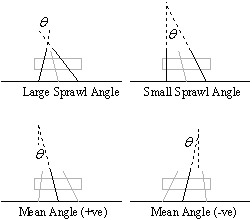 Figure. Mean angle and sprawl angle
 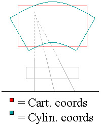 Figure. Workspace shapes for cartesion and cylindrical coordinate systems
 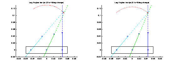 Figure. Mappings for 1D (left) and 2D (right) turn methods
 Another method of analyzing 2 dimensional leg positioning involves effective leg angles and intersection distance, and can be applied to any dimensional turning method. For the Sprawlette robots, if you extend the projections of the three legs, they will either intersect in one point or at three (provided no 2 lines are parallel). For the case of 3 intersections, the effective intersection point for all 3 legs can be considered to be the center of this triangle. The angle of the line between the middle leg mount (hip) and the (effective) intersection point can be viewed as the effective leg angle for the 3 legs. Likewise, the distance from the middle leg mount (hip) to the (effective) intersection point can be called the effective intersection distance. These two parameters can be used to describe the majority of the leg configurations on one side of the robot, no matter what n-dimensional turning method is used. It is hypothesized that the effective leg intersection point is a measure of the operation and performance of legs on one side of the body (no matter how the intersection point is derived, either by direct intersection (intersection based turn) or triangulation (non-intersection based, ie 1D iso-ips, other 2D or 3D)).
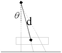 Figure. Effective distance (d) and effective leg angle (theta)
 - May have to consider servo/body dynamics in extreme turn (may have to use instant interim strategy until servos rotate or momentum builds for cont. turn strategy)
May want to investigate turning via LA increases, and also look at DC increases separately -- AMcClung? - 06 Aug 2003
Ideas, requests, problems regarding TWiki? Send feedback