new web: http://bdml.stanford.edu/pmwiki
TWiki > Rise Web>VerySmallJumpingRobots? >JumpingRobotProject (08 May 2007, UmbertoScarfogliero? )
Jumping Robot Main Page
-- UmbertoScarfogliero? 30 March 2007 For the design ideas and motivations, please refer to the attached presentations and to the articles presented at ICRA 2006, Orlando and ICRA 2007, RomeMaking the Jumping Prototype at Stanford
During the fabrication of the prototype we had to take into account several restrictions on the weight and room of the components. This constraints were imposed by the presence of the flight phase in the jump.
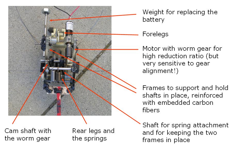
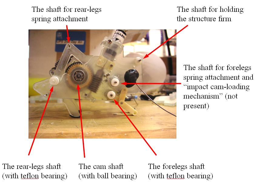
The robot has two parallel frames, on the right and left hand side, which are used to keep the motor, the cam shaft and the legs in place (see picture). In this way it is easy to assembly and dis-assembly the robot, and the cam and the legs have room to rotate in the inner part of the robot. Shafts rigidly connecting the two parallel frames keeps the whole robot firmly resistant to impacts occurring at every step. This initially was one of the main problem in making the prototype work, together with the friction forces, as explained below
The legs, the cams and the frames were fabricated using Shape Deposition Manufacturing (SDM), embedding carbon fibers to make the structure more resistant and light. The polyurethane used was mainly the Task 9 from Smooth on.
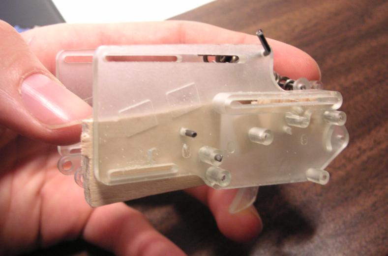
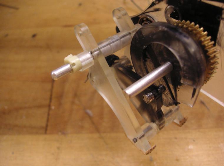
Initially the two frames were just planar, but in this way the structure was not firm. In fact due to the holes tolerances the shafts had some freedom in axial alignment.
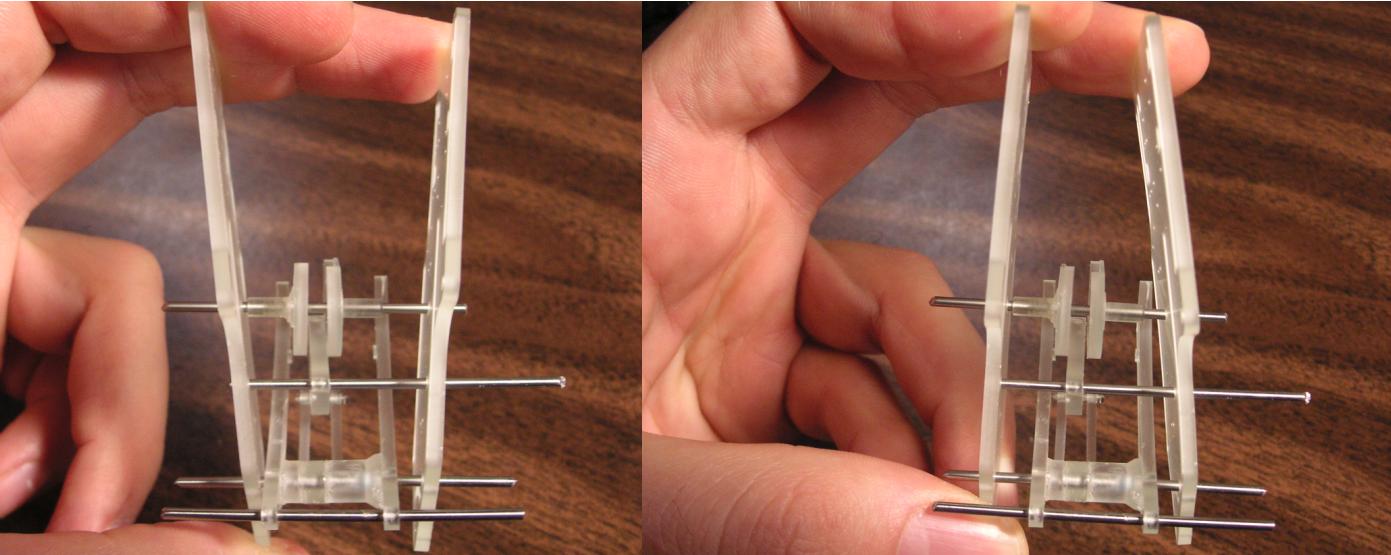
In order to improve the robustness of the structure and to keep the legs in place along the shafts, cylindrical shafts housing had to be added, renouncing to the planarity of the two frames.
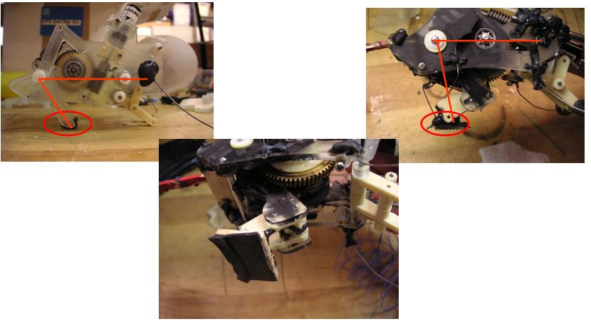
Bearings were used to reduce friction. Both metal ball bearing and sliding Teflon bearing were tested, mainly on the cam shaft (that is rotating continuously) and in some cases on the rear-legs shaft (that is rotating + - 20 deg). In this figure also the disposition of the shafts is shown.
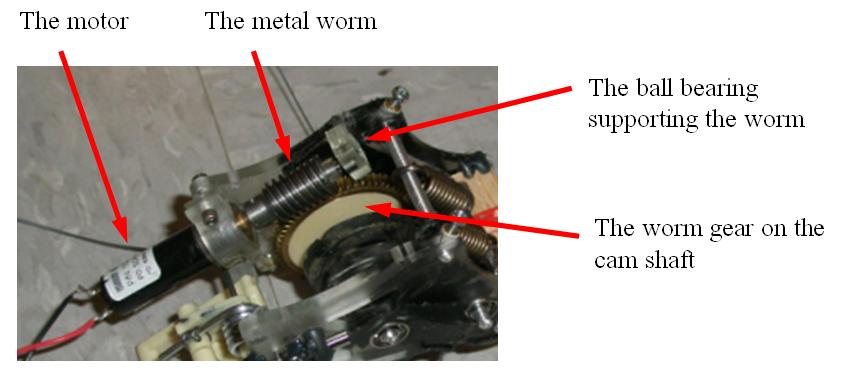
As the friction between the cursor and the cam highly influences the motor torque, small ball bearing where used for limiting the friction in the cursor. These are off-the-shelf components (ordered at McMaster-Carr), with an outside diameter of 1/8. Also the worm at the motor was supported by a ball bearing, in order to reduce the stresses on the gear head and preserve the alignment.
Alignment and axial forces in the worm-gear transmission need to be carefully taken into account when choosing this kind of transmission. In this case, using a double-thread worm wheel, it was possible to obtain a high gear ratio at the about the same efficiency of a planetary gear head (worm and worm wheel from Boston gear, planetary gear head from Fauhaber).
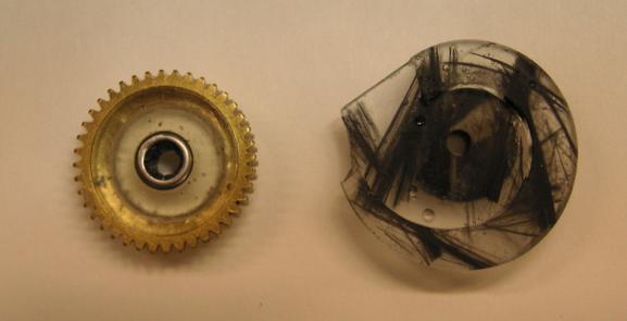
In order to reduce the weight of the metal gear, the original brass gear was cut at the lathe, and mounted on a plastic support also cut at the lathe. Using the lathe it was possible to preserve the original strict tolerance on the concentricity of the bore and gear profile. In the picture below it is shown the worm wheel with inserted a metal roller-clutches bearing and the cam made through SDM with carbon fibers embedded.
We also tried several different rear-feet design, like metal spines, sand paper or a thin sorbothane layer. This was the best solution, also useful for cushioning the impact at landing. We also tried different leg angles, to test its influence on the jump dynamics. It turned out anyway that the loction of the center of mass influence the take-off pitch rotation more than the rear-legs angles. Higher angles in addition needed higher coefficient of friction to avoid sliding in the rear feet.
Videos
- The latest video at high definition (28 Mb) and low definition (7 Mb)
- A sequence of jumps in slow motion
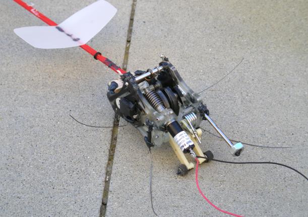
- Tail_PICT4017.MOV: A single jump with a stabilizing tail (jump length is about 1 m)
- Wings_PICT4026_s.avi: A single jump with tail and wings
Links
Ideas, requests, problems regarding TWiki? Send feedback