new web: http://bdml.stanford.edu/pmwiki
TWiki > Rise Web>TWikiUsers > IvanHerrera>IvansSummerBlog (25 Aug 2008, IvanHerrera? )
-- IvanHerrera? - 16 Jun 2008
 Below are two of the several plots I have come up with. We can see that for the given constants (F at O
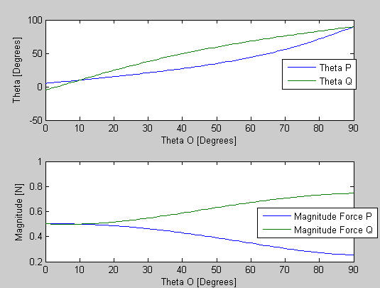
Week of June 16th
Solid Works
I had some previous experience with Inventor, which is very similar to Solid Works. Although it took a little bit to get used to I didn't find any major issues.Unigraphics
Just like with Solidworks, I had never used unigraphics, but the tutorial online proved to be very helpful. Laurel and I had a lot of trouble creating the mill operation first because we were trying to generate the code for a part that had two different depths (One depth for the side plate and a smaller plate for the actual foot). Sal helped us out and later Alan made some additional comments that weren't on the tutorial that really helped us.Haas
I also had some previous experience with Milling machines, but just like everything else the Haas is very different. Understanding the offsets and how to make wax blocks that were already used reusable was not terribly complicated, but I want to make sure that I don't get the trophy so I will have to pay close attention. Laurel and I generated the code for the feet and milled a pattern of about 130 of them. We should be making them soon.Pouring/Vacuum Chamber
Alan showed me how to prepare the mixture we use to make the feet and sideplates as well as the whole pouring process that needs to be carried out. We are thinking of ideas to make a system to handle the wax block easier in terms of putting in and taking it out of the vacuum chamber. The process is pretty straight forward and is a bit intimidating because of the need to wear protective material. I feel pretty comfortable with it though and should be easier to follow as I do it more.Week of June 23th
Toe Design
The toes we poured last week did not have a very successful yield because the materials did not cure well. We aren't sure why this happened; it could be because the material is old, it only has a shelf life of 6 months, or because we used different material, namely A20 for the flexures instead of A60. The A20 is too soft so we were unable to mill off the residue. This forced us to have to remove it by hand. Alan and I made a new Toe design which we milled and poured on Tuesday. The toe layout on the wax block looks very good, there is plenty of space and the cavities came out well.We anticipate a very good yield. The batch had a 100% success rate, which is pretty remarkable. We assembled the feet and two feet, with different toe designs, were shipped. We manually tested them, but will be testing them on the robot soon.Unigraphics and the Haas
After milling the toes and sideplates, we realized that the holes didn't go through the parts entirely. When I created the unigraphics code I overlooked the fact that the holes should be made deeper than the part to ensure that the holes go entirely through it. We were able to fix it on the spot by simply lowering the offset and running the program for the holes again. I made a note of this and made the holes deeper when generating the code for the new toe design to ensure this doesn't happen again. Alan showed me a function in Unigraphics called macro. It allows you to record the steps of a process and replay them for any part. This function makes it a lot easier to generate code for the HAAS since you can go through the steps for one part and then unigraphics will do them for every part after it, decreasing time significantly. Alan and I have milled and poured more toes, and I have generated more code for the HAAS with Unigraphics. I feel a lot more comfortable with the toe making process and I am self sufficient with SDM =).Sideplates
The side plates we poured last week turned out really well. We worked on a way to keep the rods that connect the side plates and toes in place. I found this cable which has about the same diameter as the rods. Using the cable's lining , after taking out the cable inside, proved to be a very easy way to hold the rods in place. Finding an easier way to replace the toes is another thing we looked at. After a couple of trials we found that it is very simple to remove the toes once they are attached to the foot no matter where they are located. The best way to do so is just to cut the given toe where it attaches to the rod closest to the ankle joint. After making this cut, the toe comes off. We anticipate that using the cable tubing as a fastener between the rods and side plates will make it very easy for the side plates to be removed and new toes to be attached at the end of the rods.Block Lifter
Another mini-project Alan and I are working on is making a device to handle the wax blocks easier. The vacuum chamber located in the RPL is on top of a table, which makes it very difficult to insert and take out the wax block into the chamber, you basically have to stand on the table. I have been looking online for different ways to attach handles to the block and found several options. Option 1: Turnbuckles http://safetysling.thomasnet.com/item/fittings-hardware-turnbuckles/jaw-eye-turnbuckles/1031877?&seo=110&bc=100|1007|3001151|3001065 Option 2: Short Swivels http://www.e-rigging.com/store_Categories.cfm?Cat_ID=62&Menu_Choice=Catalog We can use either of these methods to attach handles through hooks to the metal located underneath the waxblock. I think the short swivels are the best method that I have found so far.Week of June 30th
Toe design and feet
Since the two feet were shipped out last week, we are really only waiting on bSuction Cups
Alan and I made some quick prototypes using plastic bags. We had two designs. One had three concentric cups, the other hard 2 concentric cups and the smaller of the two had 4 small cups inside. Although it was difficult to tell, I feel like the design with the 4 small cups within the medium sized cup worked better. I would like to experiment more with this since it could be an approach to making a suction cup that adheres to semi-porous materials. While looking online at existing suction cups I ran into a tripod designed for cameras that employs suction cups to hold in place. It claims that these cups are able to hold to any material. It sounds too good to be true, but it might be worth looking into. (http://www.digihire.com.au/sticky-pod.htm) I also found suction cups with an added tube, which is connected to a vacuum pump. Although it is more costly and requires more peripherals, electricity and vacuum pump, it is probably the method that will work the best. If the vacuum pump is adequate and takes out air at the same rate that it leaks in, due to the porosity of the wall, it would cause the suction cup to remain attached. I found a very useful article at http://findarticles.com/p/articles/mi_m0UQX/is_2_67/ai_98643130 detailing some of the important characteristics a vacuum pump should have to work on porous surfaces. Important Characteristics:- high flow rate, not necessarily a high negative pressure.
- single stage pneumatic vacuum generator.
Fish Tank
We cleaned out the fish tank.Block Lifter
We ordered the short swivels (http://www.e-rigging.com/store_Categories.cfm?Cat_ID=62&Menu_Choice=Catalog) last Friday and should be receiving them soon. The plan is to attach the pin through the holes on the bottom metal plate of the wax block and use hooks to attach handles made with cable.Week of July 7th
<! I think you mean "stalks" not "stocks" -MarkCutkosky !> <! Also, we should talk about what the optimal shape is. !>Stalks
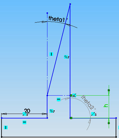
Although the stalks used on the wedges for the feet of StickyBot work well, it would be great if we could find an optimal shape to maximize the amount of weight the wedges can support. Alan informed me that Noe had mentioned this a while back, but this topic had not really been looked into. After talking with Alan and Aaron, we thought that this is something I can work on. I will SDM large stalks and change a set of parameters theta1, theta2, and h (these can be seen in the picture below). After SDMing these stalks, we can see how they behave on the force plate. This should provide us with an idea of which parameters affect the stalks' performance.
Week of July 14th
Stalks
I created a number of different designs for stalks on solidworks. Generating the Unigraphics was a little tricky since I decided to use two different tools to minimize the curvature on the points. I will be using Task 9 for the rigid backing; I hope to pour he backings by Today in the afternoon. For the actual stalk I plan on using A30 or something of the sort. I emailed Noe the designs I plan on making to see if he has any suggestions. We have been trying to model the stalks by using beam bending equations, but for some reason the models give a larger value of bending than what is observed. Although this would normally make sense since the shape is more of a cone than a beam in this case we are applying the force and measuring the displacement of the rectangular section, before it has the point so that the models should be fairly accurate. If we are able to calculate the degree at which the stalks will bend when a given force is applied we should be able to calculate the optimal angle theta 2 for the stalk points. The stalks I poured yesterday came out fairly well. There were a couple of issues like: There is a small lip on the top of each stalk because the tool I used was a little short. There is also a thin layer of wax between the task 9 (hard backing layer) and the vytaflex so I need to make sure that we cut into the task 9 with the Haas. For the next iteration of stalks I will also change the soft backing layer width and see its effectsContact Surface Analysis
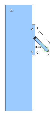
Alan and I have been making analysis of a rigid contact surface attached to a wall with a force applied at some distance d and angle theta from the center of the patch.( the picture is shown below for clarification) The patch is a height 2h. I have been making plots of how the force magnitudes at P and Q change depending on what angle the force is applied at O as well as a contact model to tell what the maximum force that can be applied before the patch comes off the wall is.
Below are two of the several plots I have come up with. We can see that for the given constants (F at O 1 N, h=1, theta 10 deg, d =.5)Point Q is going to detach first.
Climbing Wall
Alan and I made a climbing wall for spinybot demonstrations.Week of July 21st
Stalks
I have been experimenting with modifications that can be done to the stalks to improve adhesion. As it was suggested I cut a wedge in the back of a stalk to make a sort of pivot in the front section. What I noticed is that it does seem to help a bit. I think this is mostly because it requires less normal force for a larger area of the stalk to be in contact with the surface.Sangbae Stalks
Greg taught me how to pour the Sangbae stalks. This will allow us to make more as we need them to test different hierarchy/suspension designs. After pouring the tap blue on to the molds twice, we have been unsuccessful at cleaning them out properly. I used acetone, isopropyl, a tooth brush and rag to clean the molds. It took a while but I think its safe to say Greg and I were pretty successful in cleaning the molds out.Suspension
I am working on different designs for suspensions for spines or adhesives. From what I understand we want the foot to be able to adapt to an irregularly shaped wall as well as a system that allows us to use a lot of feet instead of just one. I came across a promising design and built a quick prototype which shows fairly good results. I have been working on simulating this design on working model and tweaking it so that it acts like we want it to.Week of July 28th
Suspension
I ran into a lot of trouble with working model when I remade the part to scale, working model was taking a very long time to compute everything. After taking a look at it, Alan realized that it was probably the step size (Accuracy). It works much better now that it was significantly reduced. What I am coming to realize is that if we follow with the same suspension design then we will next very strong flexures to hold the feet. The reason for this is that these suspension flexures must hold 50 or so toes, forcing them to hold roughly 8 kgs. I have continued to work with the simulations and have calculated the desired spring constants for the flexures. I am doing the last minor tweaks in Solidworks and should be able to manufacture it very soon. I began manufacturing my initial suspension design on Thursday afternoon. The flexures are currently curing. I hope to begin testing them on Monday morning/afternoon since I still need to drill a couple of holes on the side plates and tap them so we can attach the side plates to a rigid acrylic backing (just temporary).Sangbae Stalks
I tried pouring stalks twice and both of these times the layer between the two molds was too thick so the stalks would rip when they were being removed from the mold. On Wednesday we obtained some good results after we added thinner to the silicone mixture and placed a much larger amount of weight on top of the mold, when the material cures. I taught Laurel how to do it on Wednesday so now there are a couple of us that know the procedure in case more need to be made.Rise Toes
We made several modifications to the rise toes. The main issue we had with version 9 was that the toes would extend and would remain extended. This was an interesting issue, I think it mainly happened because we have so many toes per foot and the flexures touch (the flexures stick to each other) so that means when one toe extends the contracting force is not enough to overcome the sticking of it to the surrounding flexures. To fix this we made the flexures thinner. This should stop them from touching each other and allow them to retract correctly, or so we hope. I started making more toes with the new design Friday afternoon. After the first pour, Task 9, all of the fish hooks but one look like they are in position so hopefully we will have a good batch. This batch should provide enough toes for two feet and half so we will have to do another batch at least to fully outfit the Rise robot's feet with the new toe design. I plan on milling and pouring the flexures Monday, maybe even during the weekend, (all of the files are ready to go) so that we can outfit Rise asap and do some more testing.Macro Wedges
Although I haven't been able to do much with them since they are difficult to attach to the force plate (so we can get some actual data) we were thinking that I will attach some of the DPS (Sangbae's Stalks) to the macrowedges' side and see if that makes the difference in design more noticeable.Week of August 4th
Rise Toes
Monday: I finished a batch of toes today in the morning and they look fairly good. I also milled and poured some new side plates in the morning so that I can make some feet and test the new toes. The old side plates needed a couple of changes and have all been used. Tuesday: The side plates turned out well, one thing we noticed is that they bend somewhat easily. They bent while we were putting the toes through the rods. Although they are easy to bend back, this is pretty curious because I don't think this sort of thing had happened before. I think it may be because I used old Task 9. Laurel and I put together two feet of brand new toes. We tested them outside and they work very well. The design changes don't seem to have affected the issue we were having previously, there are still toes that remain extended even after they are unloaded. Not entirely sure why that is. This might not be such a huge issue but it might still be worth looking into. Nonetheless we have 5 feet of fairly new toes so we should be able to run the RISE robot as soon as Alan gets back to do some testing with the new feet. Wednesday: Made some additional changes to the toes, mainly made the overload protection thicker since Alexis found that it was breaking on their testing (Although it might just be because of how they load the toes, we figured we might as well strengthen them). We also added a spacer so the toes will be farther from each other. This spacer should keep them separate enough so that the flexures don't touch and therefore the toes retract like they should.We also tried something different with the pouring and planing. We made the toes .1 thicker and just planed it off, this should give us a more exact thickness. Previously for some reason the thickness of the hardparts was a little off. We are probably going to even add a pattern of hard material with different depths so we can tell how far down we have gone into the wax block. (make an array of holes with .02, .05, .07, etc. Thursday: Finished making the toes, we just took them all out and they came out really well. Should be testing them soon.Suspension
Monday: The suspensions I made last week did not turn out well because the material I used for the flexures is very brittle. The material I used for the flexures seems to be very old so I am guessing that is why it didn't cure well. We need to order more Vytaflex 60 since we are out, which is what i used to make the flexures and the zman toes require it as well. I noticed a small issue with the flexure design. Wednesday: Ordered Vytaflex 60 and 40.Macro Wedges
Monday: I glued pieces of the Sangbae Stalks to the macrowedges and am currently waiting for them to dry so I can see whether this allows us to test them better. Tuesday: I have been looking at the macrowedges and I noticed that adding the PDMS stalks on the tips allows us to see the stress concentrations and how they load better. If you test them on glass or acrylic you can tell which part of the macrowedge comes off first because the PDMS stalks stop touching the material. I am going to compare all of the different designs and see if I observe anything interesting. Wednesday: I used a poxy to glue the Sangbae Stalks to the macrowedges. It seems to hold better, I will finish re-gluing them and see if there is a difference.Contact Surface Analysis
Wednesday: Started working with the patch pulling analysis again, however we are adding 2 external moments to the system. One of these is at the middle of the patch and the second is located at the end of the pulling rod (where the force is applied). It would be interesting to see if we can find a combination of moments such that we increase the force the patch can hold. Adding external moments is more realistic in terms of Sangbae stalks since there is some spring force that wants to straighten them out caused by the rubber property. Thursday: Made some simulations of the patch pulling when there is an internal moment (caused by the rubber wanting to move to is original position). Found out that when we add a clockwise moment the angle at which you are able to pull increases since it keeps the bottom joint from detaching prematurely. It was also interesting to plot the limit surface graph with different moments applied because it allowed me to see how by adding a moment you trade being able to pull with more force tangentially for being able to pull with more normal force) this is interesting because it would allow us to pull with a bigger angle in respect to the wall without the patch coming off (might be something we want for zman).Week of August 11th
Suspension
Monday: The Vytaflex I ordered last week should be coming in today. Unfortunately Tom is using the haas for the next day and a half, which means I'll have to wait until Wednesday to pour anything, including toes.Contact Surface Analysis
Monday: I have been simulating the contact limit surfaces for varying parameters (height of patch,and pull radius). I have also added Moment calculations to the simulation. This means that we can calculate the necessary moment to make any configuration match the optimal contact limit surface, when the pull radius=0, at any given point. Tuesday: I have been plotting different contact limit surfaces for varying angles of the rod from which we pull to determine what is the optimal limit surface that we should approach. Thursday: I have been calculating the torsion coefficient that we would want in a patch that uses PDMS stalks. (The torsion coefficient at both the joint with the backing layer of the patch and at the joint that the rod would make contact with the backing of the surface we would eventually attach to SB. I also made some measurements on the torsional coefficient of vytaflex so we can calculate what width, height, and length we would want the flexures to have. The Haas is still occupied. Friday: I calculated a pretty good approximate of the vytaflex torsional coefficient and calculated what dimension we would like the flexures of the hierarchical structure for patches to have. Started working on Solidworks to design some possible structures.Rise Toes
Wednesday: Alan has been changing the toe design significantly so we should be running another batch of toes very soon. I finished the Unigraphics so we are ready to Mill as soon as the Haas is available.Week of August 18th
Contact Surface Analysis
Monday: Worked on graphing the contact models for varying pull forces and pull angles. The Haas is still in use. Tuesday: I am running more simulations to see how the height of where the rod is attached to on the pad changes the contact model. I have been changing other parameters such as the length of the rod, changing this parameter has no effect. I have also been changing the ks, location of the rod on the patch and the angle of the rod. Wednesday: We found some "errors" in the code we had been running for simulations so Alan decided to look it over himself. I began exploring what would happen if we simulated a similar system that had a "spur" on the bottom for stability. This spur would much like StickyBot's tail. However, I realized that the system is statically in determinant because the contact point of the spur adds too many variables. The script for the patch simulation is mostly fixed, it displays what it should (the method that we had used before for finding the points at which the patch comes off was leaving out a large part of the solutions so that the plots were mostly straight it would fill in whatever was missing instead of being curved). I began building physical models to see if our simulations were accurate. I used the flexures in Laure's old 4 bar linkages and although they have fairly low K constants they do behave very similarly to how our simulations state they should. Thursday: Poured more DPS stalks. I have been changing some of the parameters on the new (more accurate) simulation and noting the results these changes have on the contact surface. Made a Matlab script to calculate the distance that is needed between two patch systems so that they do not collide with each other. (since we plan on putting one below the other in some sort of suspension)DPS Stalks
Friday: The DPS stalks that were poured yesterday turned out ok. I feel like the lack of thinner was a reason for this also we could have pressed harder on the sections that did not turn out as well. I poured more this morning, this time I found an RTV Silicone thinner that I used. (10% of the Part A) Sunday: I checked the DPS stalks that I poured on Friday and they came out great. I told Laurel what thinner she needs to use now so that they turn out well.Rise Toes
Friday: Milled and poured the hard parts for a batch of the new version 12 toes. Milled the suspension design that I had been working on. Poured the hardparts of the suspension. Saturday: Milled and poured the flexures for a batch of toes. Milled the flexures for the suspension design. Poured the flexures for the suspension. Sunday: Finished a batch of toes. Milled the hardparts for the toes on two wax blocks. Milled the holes on the suspension design. Milled side plates for the feet.Week of August 25th
Rise Toes
Monday: Placed the fishhooks in both of the wax blocks that I milled Sunday. Poured the hardparts for both wax blocks. Poured the hard parts for the side plates. Finished the Side plates. Toe v12 is not as good as we thought it would be. We noticed that version 11 is actually very good, so we might just decide to mass produce that one. However, since the hardparts of toe v 12 are curing I am looking at how we can change the flexures so that Toes v12 works well enough and we can use what I poured earlier today.Ideas, requests, problems regarding TWiki? Send feedback