new web: http://bdml.stanford.edu/pmwiki
TWiki > Rise Web>ClimbingRobot > StickyBot > StickyBotMechanical>HysteresisReductionInCompliantShoulder (02 Jul 2007, AnnaShedletsky? )
Reduction of Hysteresis in Arm Link/Compliant Shoulder
Improvements to arm link and shoulder to reduce hysteresis in order to make the stroke sensor readings more realiable.Definition of Problem
The original compliant shoulder design consists of the longer arm link and compliant shoulder. The compliant shoulder includes a joint made of soft polymer and is driven by the servo -- it is attached to the arm link by two screws, which transmit the force of the servo and move the leg. The arm link is outfitted with a hall effect sensor (StickyBotForceController) which is set between two magnets glued to the compliant shoulder. During use, the current arm link does not fully return to its original position, and remains offset from the shoulder (which is what is driven by the servo). As the hall effect sensor is sensitive to even small changes in position, this hysteresis makes the sensor less reliable and not as useful. The goal is to redesign the component such that hysteresis is eliminated or reduced. Original Compliant Shoulder Design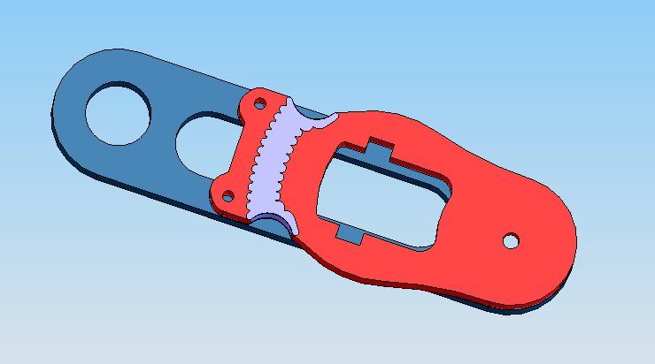 -- AnnaShedletsky? - 28 Jun 2007
Design Brainstorm
Brainstorm of Properties Causing/Mitigating Hysteresis
Relating to the Stiffness of the Polymer- Temperature of soft polymer
- As the robot moves and flexes the compliant joint, the soft polymer heats up which could make it softer, although the extent of the effect may be small.
- Cross-sectional area of soft polymer
- A larger cross-sectional area will increase the stiffness of the joint.
- Tension in the soft polymer
- Increasing the tension in the joint will increase its stiffness -- perhaps enough to overcome opposing forces (friction, etc).
- Friction
- Friction forces between the faces of the arm link and the shoulder, as well as in the hole on the armlink that slides around the servo horn, could oppose the returning force of the joint, preventing it from returning to its original spot.
- Geometry of the soft polymer connection
- Most of the joint connections with the soft polymer have similar geometries. It may be possible to alter this geometry slightly to make a slight offset create more stress in the material so that there is a larger returning force.
Possible Edits to the Current Design
Reduce Friction Between Components Currently, the compliant shoulder is screwed to the servo through the arm link. This creates friction around the servo hole and between the faces of the components when the components try to move. Even with care, the four limbs are also all tightened different amounts, creating variable amounts of friction. On the sample components, tightening the screw connection causes the shoulder piece to bow slightly between the servo joint and the screws -- leaving a sliver of space between the faces of the components near the soft polymer, but increasing the normal force near and around the servo joint. The proposed change would be to create an inset ledge on the arm link (as it's the simpler part to make and to modify) that would reduce the contact between the faces. Design to Reduce Face Friction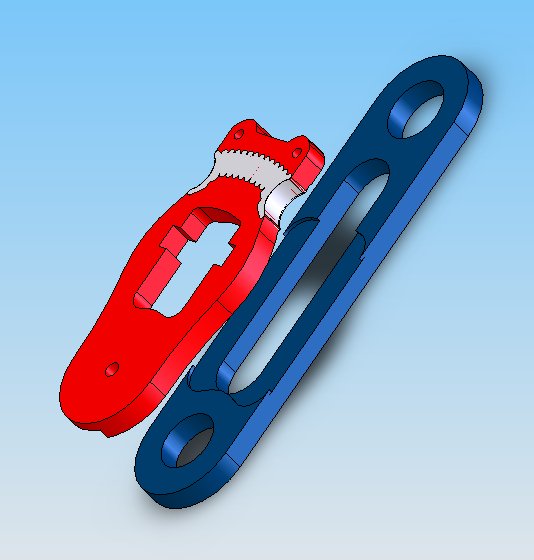 -- AnnaShedletsky? - 29 Jun 2007
Increase Stiffness of the Soft Polymer: Cross-Sectional Area
The stiffness of the compliant joint will be increased with a thicker cross-section. This design fits within the dimensional constraints of the original joint components, but will apply more returning force because of the stiffer joint. How significant the stiffness change will be in unknown.
Design to Increase Stiffness Via Cross-Section
-- AnnaShedletsky? - 29 Jun 2007
Increase Stiffness of the Soft Polymer: Cross-Sectional Area
The stiffness of the compliant joint will be increased with a thicker cross-section. This design fits within the dimensional constraints of the original joint components, but will apply more returning force because of the stiffer joint. How significant the stiffness change will be in unknown.
Design to Increase Stiffness Via Cross-Section 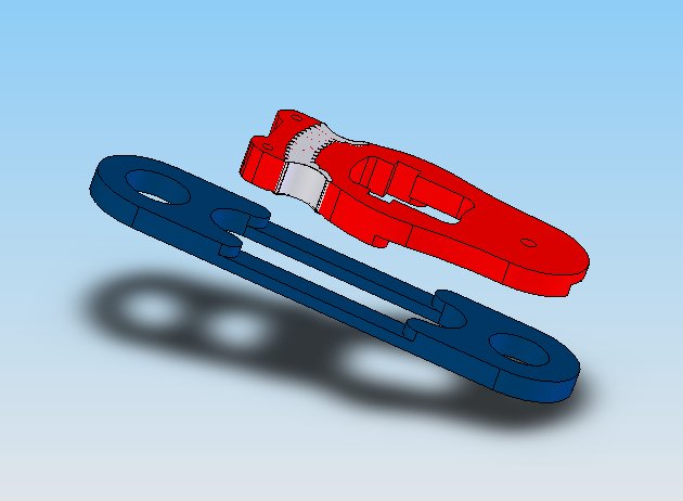 -- AnnaShedletsky? - 29 Jun 2007
Increasing Tension in Soft Polymer
Barrett's idea to increase the stiffness of the joint is to cast both of the parts as is, but to screw the compliant shoulder on to the arm link with the joint in tension.
Currently, there is 34.12 mm between the center of the servo joint and the location of the screws. The unloaded 20A joint is ~5.3 mm and can be stretched (with only slight necking) to ~6.8 mm; so this design would move the tapped holes in the arm link to a distance of 35.6 mm. This pre-stretch should increase the returning force of the joint.
-- AnnaShedletsky? - 29 Jun 2007
-- AnnaShedletsky? - 29 Jun 2007
Increasing Tension in Soft Polymer
Barrett's idea to increase the stiffness of the joint is to cast both of the parts as is, but to screw the compliant shoulder on to the arm link with the joint in tension.
Currently, there is 34.12 mm between the center of the servo joint and the location of the screws. The unloaded 20A joint is ~5.3 mm and can be stretched (with only slight necking) to ~6.8 mm; so this design would move the tapped holes in the arm link to a distance of 35.6 mm. This pre-stretch should increase the returning force of the joint.
-- AnnaShedletsky? - 29 Jun 2007
Other Methods of Compliance
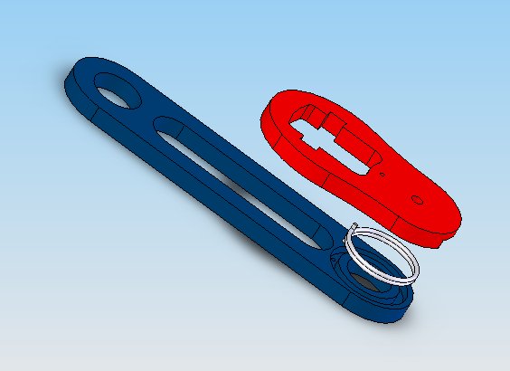
Use of Torsional Spring In Progress Metal has more reliable elastic properties than polymers; this design incorporates a metal torsional spring as a replacement for the soft polymer joint. It requires a more ambitious redesign of the arm link and compliant shoulder, as the force is transmitted from one to the other at the joint and not somewhere along the length of link, however, with machined torsional springs (which are by definition very precise and do not require "standard sizing") the joint should be more reliable. Wound versus Machined Springs(Reference: http://www.designworldonline.com/ArticleDetails.aspx?cid=262&id=527) While wound springs are cheaper to manufacture, they are also less reliable and have residual stresses in the material because of the forming process. Machined springs are more expensive (although still affordable), but they can be made to exact specifications with smaller tolerances, and can have specific end/attachment conditions only possible with machined parts. The only drawback to machined springs is the length requirement is greater -- the space within the 6 mm thick arm/shoulder component is limited, although could be redesigned. I am awaiting a response from Helical Products Company to determine the minimum length possible. Torsional Spring Design Information
(Reference: http://www.foxvalleyspring.com/Home/TechCorner/TorsionSprings/tabid/73/Default.aspx) Since the joint needs to move back and forth, the torsional spring will be repeatedly wound and unwound. While this is not recommended, it is commonly done. It may decrease the life of the spring, but this is mitigated with low rotation angles (SB probably doesn't need more than 30 degrees in either direction). I am awaiting more information from Helical Products Company concerning loading in both the wind and unwinding directions. The number of coils can vary between 3 and 30. Also, the ratio between ID and wire diameter is most reliable when the value is between 3 and 33. Research Contact:
Helical Products Company in Santa Maria California -- offers machined torsional springs. (http://www.heli-cal.com/Html/Products/Springs.htm) -- AnnaShedletsky? - 02 Jul 2007 Replace Soft Polymer with Torsional Spring
 -- AnnaShedletsky? - 29 Jun 2007
 Ideas, requests, problems regarding TWiki? Send feedback