new web: http://bdml.stanford.edu/pmwiki
TWiki > Main Web>TWikiGroups > SeabedGroup>UnderwaterSensor (08 May 2010, StephenHibbs)
-- StephenHibbs - 08 Feb 2010
Stephen Hibbs and Kevin Ting Winter 2010
--Inner gel ---
-- Inner gel originally used was SmoothOn? Ecoflex 00-10A. The problem is that the gel never fully hardens and always has a slimy/oily surface finish, even in the smooth-on sample. This gel also had hysteresis issues.
SmoothOn? Ecoflex 00-50 was instead chosen due to it's cured surface finish and lower hysteresis. The gel is stiffer however, and has yet to be tested. A current issue with the gel is that it is very viscous uncured, and cannot be easily injected into the mold with our current syringes and needles.
--tests showed that if a "bathtub" mold is over-filled with gel, then degassed and covered with the sensor plate, there is a clean, bubble-free boundary between the sensor and gel.
--Vertically-oriented molds were also considered as a means to reduce bubbles, but due to geometry issues that prevented the use of fabric with that shape (ie hard-cornered cylinder) it was ruled out, and tests showed it was unnecessary.
-- Version 3 was made with a pressure-injected gel into a flexible cavity, however the smooth-on couldn't be injected with our syringe tips. Instead the dow-corning gel was used, but that has it's own drawbacks due to softness, fast cure time, and difficulty of obtaining it. There were also air bubbles in the mold.
--Outer gel--
--Originally TAP blue (a 25 shore tin-cured gel) was used as the outer waterproofing layer, however there was incompatibility between the tin cure of the TAP and platinum curing of the inner gel, which is suspected to have led to the inner gel seeping out through the outer TAP layer
--Instead SmoothOn? Dragon Skin 20 shore has been chosen because it cures quickly and has desirable durability and hardness. It is a platinum-cured silicone gel.
--Neoprene (~50um thick) was used, stretched over the sensor like a drum for the pressure-injected sensor of version 3.
-- Conductive Layer --
-- The conductive, stretchable lycra fabric was chosen for the grounded conductive layer because it can be easily stretched over a domed or cylindrical surface and glues well to TASK 9 polyeurethane with cyanacrolite glue. It's low resistivity and total coverage is also great. One problem with the fabric is that it limits the shape of the inner gel because it can't be stretched over hard corners consistently. This requires that we use a circular or cylindrical dome.
--Another option considered was zoflex and wacker conductive rubber for the conductive layer. Options were to cut and apply pre-made sheets of the material, or to apply it to gel dome and let it cure. However, the difficulty of molding and applying a consistent layer of the material was too great. If a way of repeatably making this material of the right shape is found, it may prove to be a better choice due to higher resilience. The main issue was that Wacker is difficult to mold (it is extremely viscous and must be baked at ~130C), and we assumed that zoflex alone would lack proper conductivity or durability. In theory though, it should be possible to mold zoflex relatively easily.
--Conductive inks and other easily applied conductive layers were advised against due to their lack of durability and flexibility, but were never actually attempted.
--Current production plan --
- The Design is to first embed an unshielded sensor board in the top of a TASK 9 cylinder, with the wires coming out the "bottom" of the block. The block will then have the gel dome molded on, then the conductive fabric will be separately stretched over the back and dome to provide a conductive layer. This entire block will then be molded into a larger TASK 9 block. This assembly will then have a waterproof gel mold over the top surface, and a gasket will attach to this with screws in order to hold the waterproof layer on.
Protoype 1
 --rectangular, shielded sensor mounted on to piece of acrylic and molded on with epoxy. This was then taped to a half-cylinder and the gel (ecoflex 00-10) was vertically poured in to this, and degassed, with excess running out one end of the cylinder. Excess was then cut off and a premade layer of wacker and zoflex was cut and wrapped around the sensor and gel. Zoflex was used to connect the difference parts of the rubber. However, there were noise issues, with the sensor reading false touches when a hand was brought near the surface. (NOTE- it is currently not known if that was due to the conductive layering, or noise coming in the wire)
-To remedy this, the device was further wrapped in conductive fabric (this seemed to fix the issue) and the entire assembly was coated in TAP blue 25 shore gel.
-Issues- when placed into water with a long wire, the sensor read a huge range of false values and could not be re-zeroed properly, suggesting noise coupling in the input wire. Tests showed that the chip on the board was extremely sensitive to input voltage fluctuations.
- Also, the inner gel slowly seeped out through the outside.
Prototype 2 (the one that went to Norway with the searig guys)
BIg changes :
-The corners on this version were rounded, but it was still a cylindar and used the rectangular shielded sensors.
- A 5V voltage regulator was added to the board and attached. This solved the input noise issues with a long wire in the water.
- The wacker/zoflex layer was bypassed and instead the sensor was wrapped in conductive fabric.
-TAP was still used for the outer layer and ecoflex 00-10 was used for the inner layer. Eventually much of the eoflex sweated out of surface the sensor, leaving an air bubble within.
-Issues- the sensor "stuck" at a certain value over a range of forces, but below and above that section, the sensor had fairly continuous readings.
-This version proved that the noise could be blocked through input voltage regulation, but the discontinuity in sensor readings the leaking of the inner gel still must be addressed.
Prototype 3 (Balloon Method)
--rectangular, shielded sensor mounted on to piece of acrylic and molded on with epoxy. This was then taped to a half-cylinder and the gel (ecoflex 00-10) was vertically poured in to this, and degassed, with excess running out one end of the cylinder. Excess was then cut off and a premade layer of wacker and zoflex was cut and wrapped around the sensor and gel. Zoflex was used to connect the difference parts of the rubber. However, there were noise issues, with the sensor reading false touches when a hand was brought near the surface. (NOTE- it is currently not known if that was due to the conductive layering, or noise coming in the wire)
-To remedy this, the device was further wrapped in conductive fabric (this seemed to fix the issue) and the entire assembly was coated in TAP blue 25 shore gel.
-Issues- when placed into water with a long wire, the sensor read a huge range of false values and could not be re-zeroed properly, suggesting noise coupling in the input wire. Tests showed that the chip on the board was extremely sensitive to input voltage fluctuations.
- Also, the inner gel slowly seeped out through the outside.
Prototype 2 (the one that went to Norway with the searig guys)
BIg changes :
-The corners on this version were rounded, but it was still a cylindar and used the rectangular shielded sensors.
- A 5V voltage regulator was added to the board and attached. This solved the input noise issues with a long wire in the water.
- The wacker/zoflex layer was bypassed and instead the sensor was wrapped in conductive fabric.
-TAP was still used for the outer layer and ecoflex 00-10 was used for the inner layer. Eventually much of the eoflex sweated out of surface the sensor, leaving an air bubble within.
-Issues- the sensor "stuck" at a certain value over a range of forces, but below and above that section, the sensor had fairly continuous readings.
-This version proved that the noise could be blocked through input voltage regulation, but the discontinuity in sensor readings the leaking of the inner gel still must be addressed.
Prototype 3 (Balloon Method) 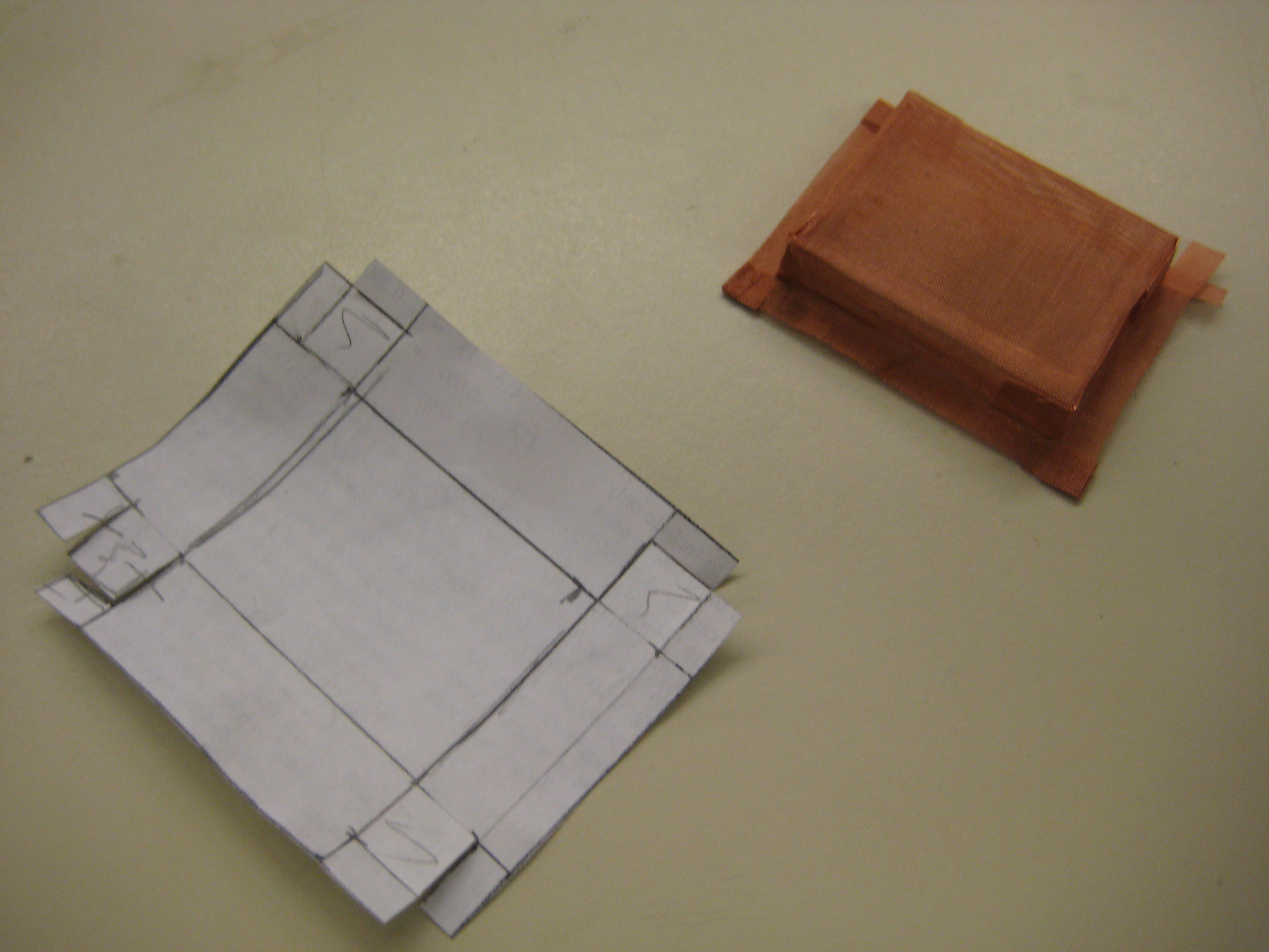
--rectangular, shielded sensor mounted on to piece of acrylic and molded on with epoxy. This was then taped to a half-cylinder and the gel (ecoflex 00-10) was vertically poured in to this, and degassed, with excess running out one end of the cylinder. Excess was then cut off and a premade layer of wacker and zoflex was cut and wrapped around the sensor and gel. Zoflex was used to connect the difference parts of the rubber. However, there were noise issues, with the sensor reading false touches when a hand was brought near the surface. (NOTE- it is currently not known if that was due to the conductive layering, or noise coming in the wire)
-To remedy this, the device was further wrapped in conductive fabric (this seemed to fix the issue) and the entire assembly was coated in TAP blue 25 shore gel.
-Issues- when placed into water with a long wire, the sensor read a huge range of false values and could not be re-zeroed properly, suggesting noise coupling in the input wire. Tests showed that the chip on the board was extremely sensitive to input voltage fluctuations.
- Also, the inner gel slowly seeped out through the outside.
Prototype 2 (the one that went to Norway with the searig guys)
BIg changes :
-The corners on this version were rounded, but it was still a cylindar and used the rectangular shielded sensors.
- A 5V voltage regulator was added to the board and attached. This solved the input noise issues with a long wire in the water.
- The wacker/zoflex layer was bypassed and instead the sensor was wrapped in conductive fabric.
-TAP was still used for the outer layer and ecoflex 00-10 was used for the inner layer. Eventually much of the eoflex sweated out of surface the sensor, leaving an air bubble within.
-Issues- the sensor "stuck" at a certain value over a range of forces, but below and above that section, the sensor had fairly continuous readings.
-This version proved that the noise could be blocked through input voltage regulation, but the discontinuity in sensor readings the leaking of the inner gel still must be addressed.
Prototype 3 (Balloon Method) - Link to video of balloon sensor working : http://www.youtube.com/watch?v=iZaaJDjjP_8
- Gasket cracked when tightened over ground connection between fabric and cage
- Don't use a wire, line up fabric with cage edge and avoid raised lumps
- Or use a more flexible gasket material
- Filling & tapping holes took a long time.
- Mold holes into base block to resolve, and use the tapping rig to speed up tapping.
- Water can contact conductive fabric layer on side of gasket.
- Try having raised lip to remedy
- Use caulk or large O-ring
- Trouble getting to ground electrical connection of faraday cage.
- Try having sensor recessed so that we can belt sand top surface to get to faraday cage. Issue here is that it will conflict with our raised lip.
- Large size of complete sensor assembly
- Try not using a circle. Try using less flaps on faraday cage (only need 1 to connect to).
- Trouble Releasing base block from mold
- Need to have mold release under sensor. A flexible mold will help this as well.
- Faraday cage staying at top of base block.
- Try gluing down. Same for sensor
- Making faraday cage.
- Try making block to fold around
- Trouble getting holes into outer membrane without tearing.
- Using thin wall tube as punch worked. Using a real punch would be a good idea
- Tapped holes only went partway through.
- Use an end tap or have holes deeper to start.
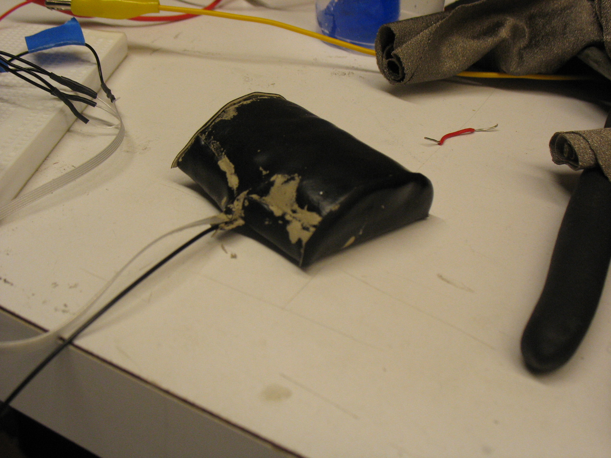
- Back of sensor is far from flat.
- Route wires out the side a little more so the back can be sanded.
- Bubbles in gel
- Find a new gel that has a longer cure time so that we can degas before putting into the syringe.
- Gasket cracked above wire connecting fabric to ground
- Need to have smooth & level surface under gasket (recess wire?)
- Air pocket under neoprene
- inject from top, letting air out as we go
- Fabric slid around and tore a bit
- Glue fabric to neoprene
- Desirable gel will have:
- extremely low viscosity so that it can be injected through a syringe
- relatively long pot life (60+ min) so that there is time to degas the gell and then inject it before it starts to harden
- little to no elastic hysteresis * Some possibilities
- Dow Corning® 3-4680 Dielectric Silicone Gel Kit ('''Used first time, to replace''')
- working time: <10min
- Cure time: 15min/30min @ room temp
- viscosity: 275cps
- Dow Corning® 3-4170 Dielectric Silicone Gel Kit ('''seems most promising''')
- working time: >24hr'
- Cure time: N/A @ room temp, 9min @ 100C
- viscosity: 475cps
- Dow Corning® 3-4190 Dielectric Silicone Gel Kit
- working time: >60min
- Cure time: 30hr @ room temp, 9min @ 100C
- viscosity: 250cps
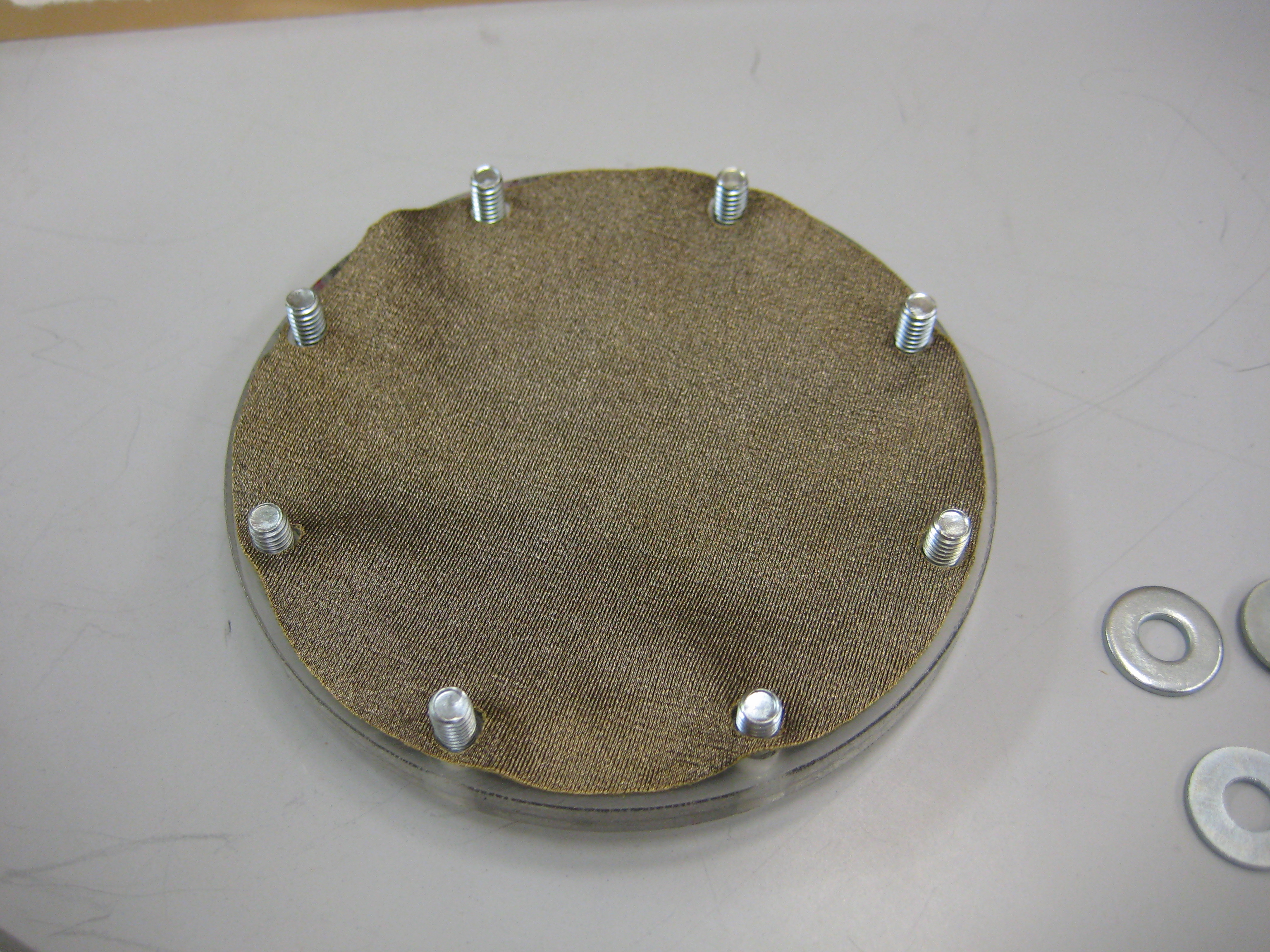
- Copper Mesh Faraday Cage with Pattern:
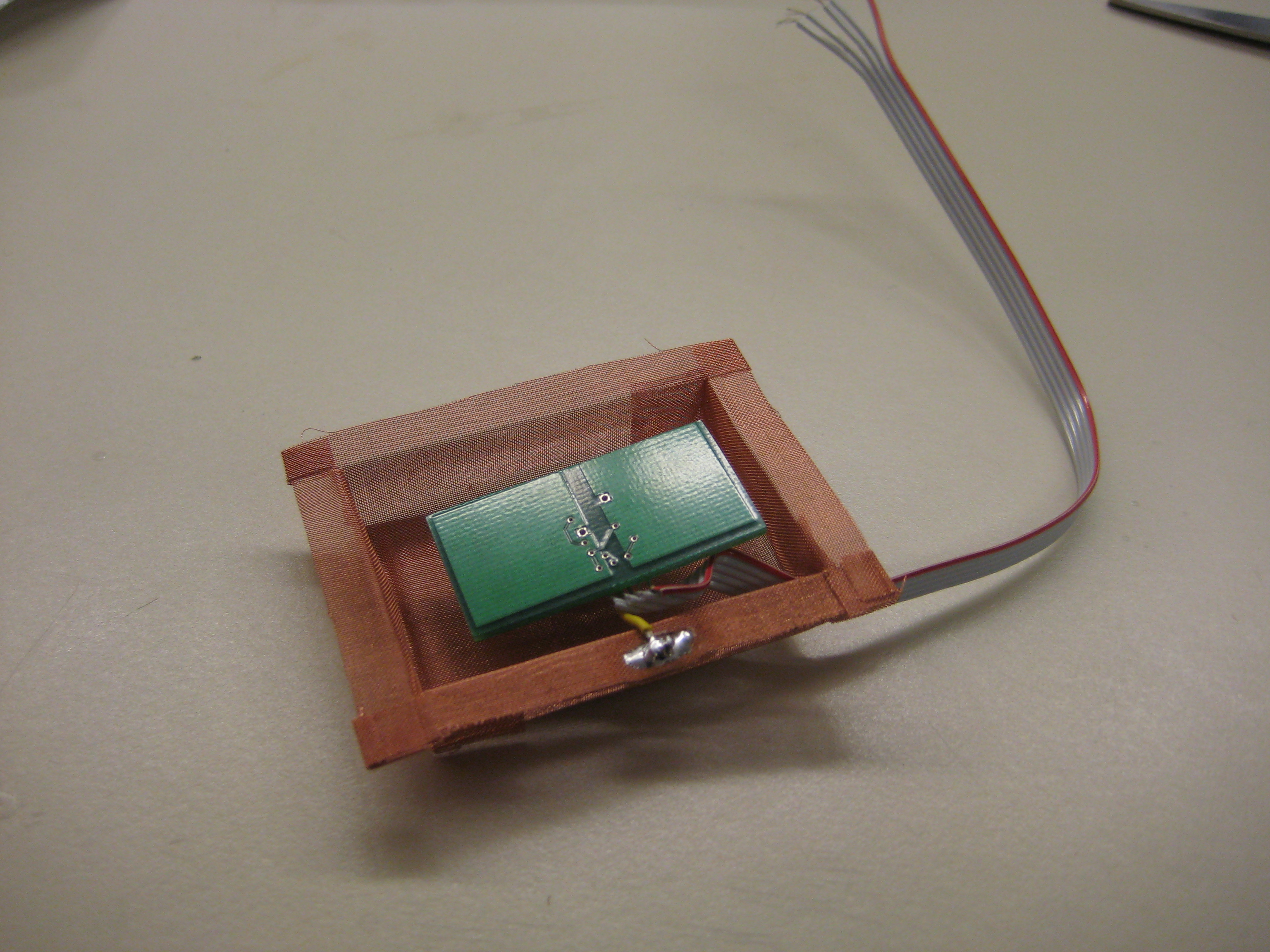
- Copper Mesh Faraday Cage with Sensor Chip:
- Task 9 Base Block With Sensor & Copper Mesh Back Shielding:
- Laser Cut Conductive Fabric Layer:
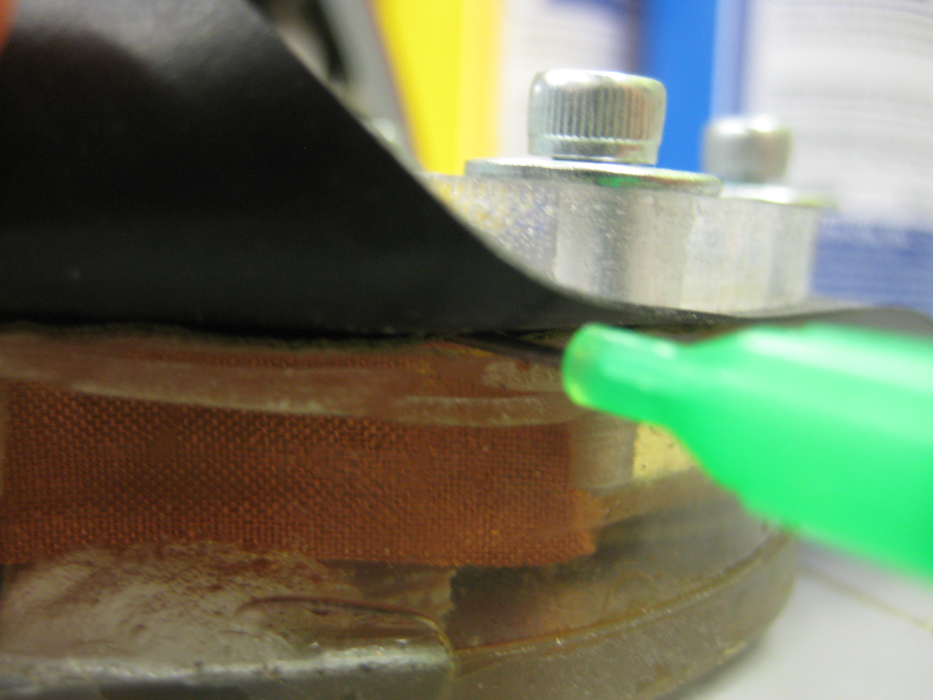
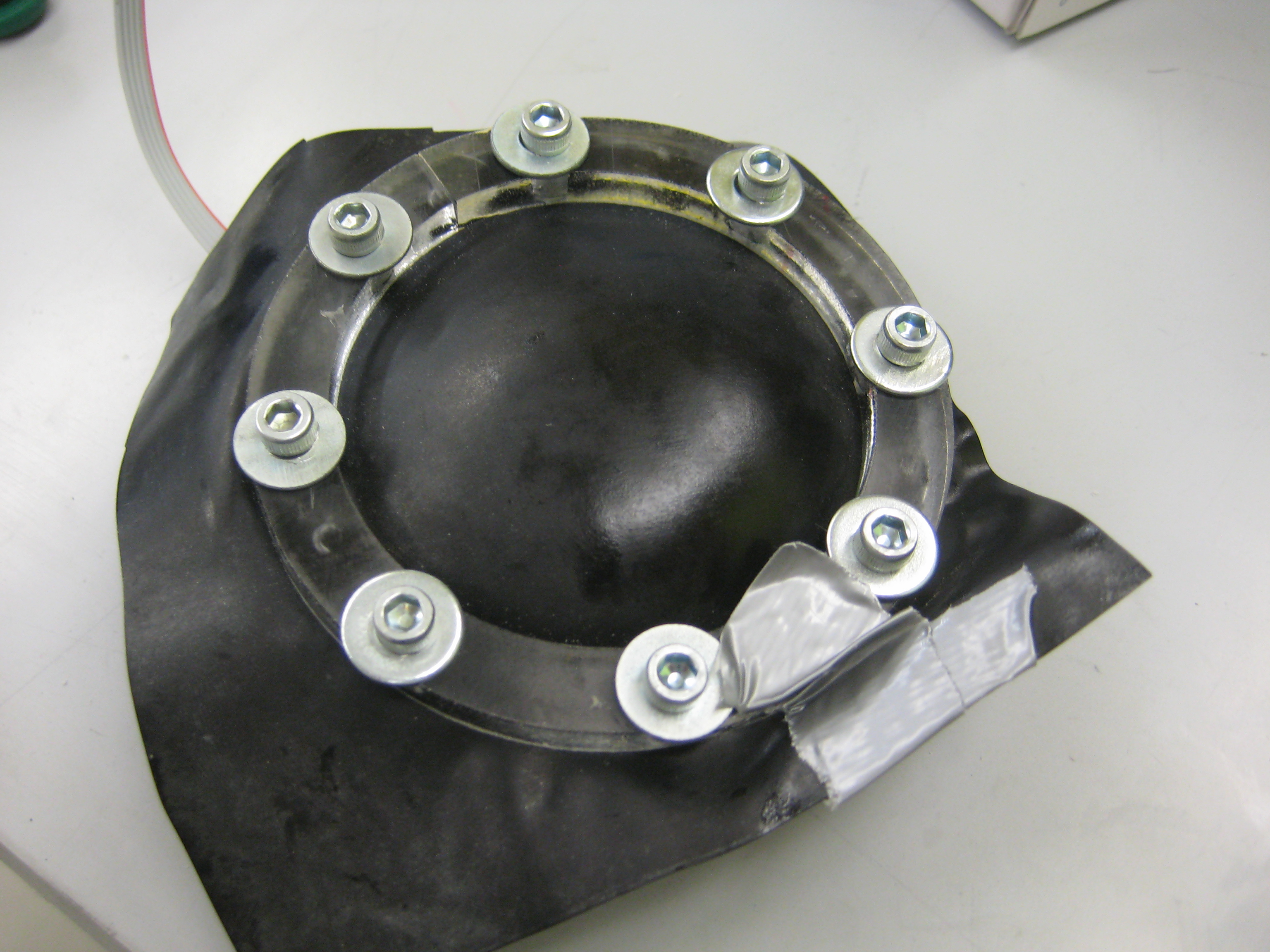
- Injecting Gel Inside of Gasket to From "Balloon":
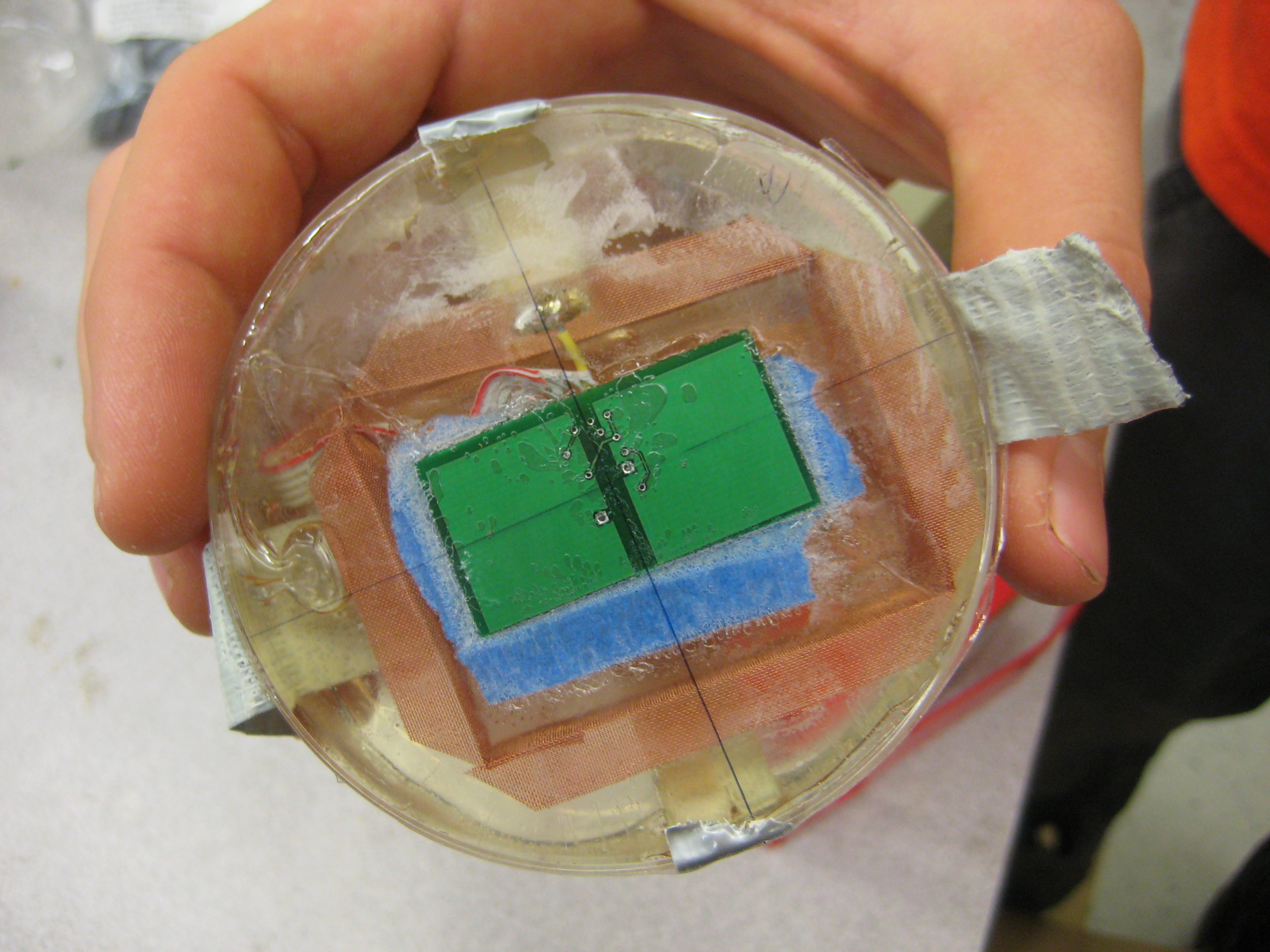
- Completely Assembled Sensor:
Ideas, requests, problems regarding TWiki? Send feedback