new web: http://bdml.stanford.edu/pmwiki
TWiki > Main Web>TWikiUsers > MarkFrykman>MarkFrykmanSummerBlog (29 Nov 2010, MarkFrykman)
-- MarkFrykman - 19 Jul 2010
Mark Frykman Summer Blog
* pro/E CAM tutorial: tutorial
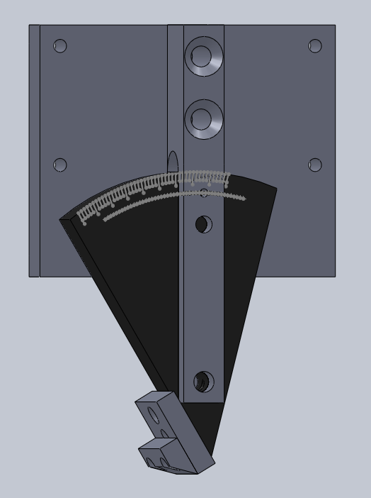
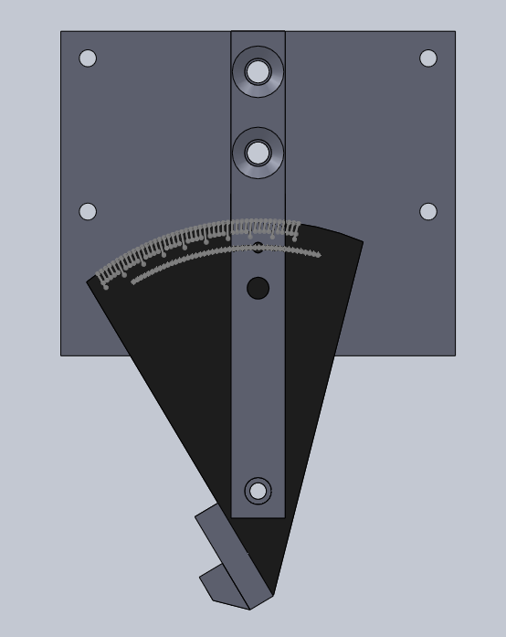
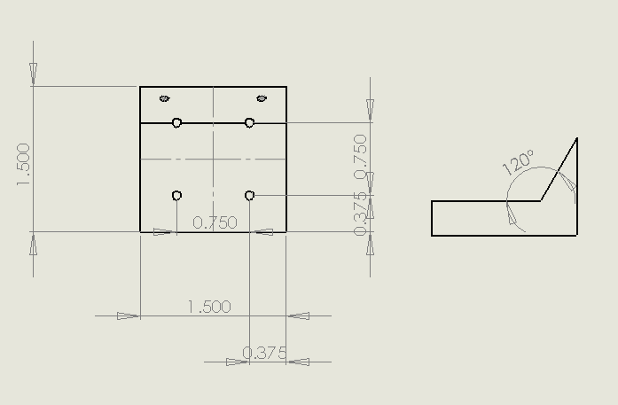
* SolidCAM? tutorials: list of tutorials. With Sydney, your SolidCAM? Professor. Week 6: July 26 - July 30 * Dan's out of town in NYC with his new wife (congrats to them) looking at apartments near Columbia. In the mean time, he's been sending me chapters of his thesis to proof and send back notes. It's interesting stuff, and most of my critiques probably stem from my ignorance of the literature on the subject. * Since Dan's out of town and I can only write Python code for so many hours per day, I decided after talking with Mark that I'm going to make an adjustable indenter holder for the Levil machine. I designed and CAD'd most of it this week with feedback from Marcus. I originally designed a holder similar to the one that I machined for Paul, but with an adjustable tool clamp that was connected with a pin joint to the main part of the holder. My plan was to constrain the hinge with two opposed machine screws; one machine screw would go through a slot on the clamp part of the mechanism and provide a downward constraining force on the clamp, and the other machine screw would come out of the main body of the tool holder and provide an upwards force on the clamp. The pin joint would be a precision shoulder bolt: After showing this design to Marcus, though, he pointed out that the Levil spindle doesn't have the same style bolt-pattern for mounting tool holders as Paul's machine. Rather than having four bolt holes on the spindle in a parallel plane to the surface of the work material, the bolt pattern is on the front of the spindle in the x-z plane with respect to the work surface. Marcus also showed me his laser cut prototype razor blade holder, which inspired v2.0 of the adjustable Levil holder. After _ hours of solidworks, I finished the first version of the CAD:
* SolidCAM? tutorials: list of tutorials. With Sydney, your SolidCAM? Professor. Week 6: July 26 - July 30 * Dan's out of town in NYC with his new wife (congrats to them) looking at apartments near Columbia. In the mean time, he's been sending me chapters of his thesis to proof and send back notes. It's interesting stuff, and most of my critiques probably stem from my ignorance of the literature on the subject. * Since Dan's out of town and I can only write Python code for so many hours per day, I decided after talking with Mark that I'm going to make an adjustable indenter holder for the Levil machine. I designed and CAD'd most of it this week with feedback from Marcus. I originally designed a holder similar to the one that I machined for Paul, but with an adjustable tool clamp that was connected with a pin joint to the main part of the holder. My plan was to constrain the hinge with two opposed machine screws; one machine screw would go through a slot on the clamp part of the mechanism and provide a downward constraining force on the clamp, and the other machine screw would come out of the main body of the tool holder and provide an upwards force on the clamp. The pin joint would be a precision shoulder bolt: After showing this design to Marcus, though, he pointed out that the Levil spindle doesn't have the same style bolt-pattern for mounting tool holders as Paul's machine. Rather than having four bolt holes on the spindle in a parallel plane to the surface of the work material, the bolt pattern is on the front of the spindle in the x-z plane with respect to the work surface. Marcus also showed me his laser cut prototype razor blade holder, which inspired v2.0 of the adjustable Levil holder. After _ hours of solidworks, I finished the first version of the CAD:
I cut several test bolt hole patterns to make sure that the holes on the holder will line up with the holes on the spindle of the Levil (the bolts are a rectangle pattern 80mm wide, 36mm high. The bolts are M4 0.7). The hinge will be a precision shoulder bolt, and there will be a small ball-spring plunger and ball detents to provide tactile semi-discrete adjustment from 0 degrees vertical to 45 degrees. There will be a small quarter-twenty socket screw that will allow you to lock the delrin disk at a certain angle. I'll be using my nice new carbide .5" square EM to cut the for the disk in the aluminum fork--this will make sure the disk fit will be snug. The .25" legs on the fork should be thin thick enough to be rigid, but thin enough that tightening or loosening the should screw pin joint will result in more or less friction when moving the disk. I'll use .5" thick plate aluminum left over from some water-jet cutting tests for the mounting plate and fork, and delrin for the disk. Thinner aluminum will be used for the actual tool clamp when I get there. The delrin disk will be CNC'd by none other than the Levil, making it the first real part to be machined on that mill.
I put together a list of hardware from McMaster? to put it all together. It should come next week some time.
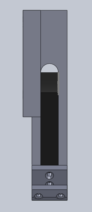
I also had time on Friday to machine the first part of the holder--the fork. It turned out well:
* I coded up the effective-stiffness model that Dan asked me to do last week. Had some debug problems, but no more so than usual. When I plotted the effective stiffness of the angled beam from 0 (vertical) to 90 (actually, to 89) this is what it looked like:
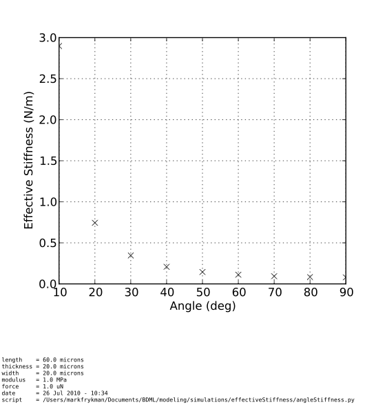
Hopefully, this script will be useful when people want to play with the indenting angle for the wax molds. As it is, I think Dan's going to add it to his thesis which is cool. It's also interesting that we're planning on indenting at about 30 degrees. If you look at the plot, the effective stiffness has already dropped most of the way by this point, and by 45 degrees, the effective stiffness is fairly close to that of 90 degrees. It makes sense that if we wanted to minimize effective stiffness without compromising other characteristics of the micro-wedges, this would be the range to experiment with.
Week 5: July 19 - July 23
* Got back from LA, and Dan has got a pretty cool new modeling problem for me to think about. Because of the current method of making the micro-wedges for the arrays (photolithography), one of the sides of the wedges must be vertical while the other is angled. Dan is interested, however, in trying to model a micro-wedge that is angled rather than vertical--for example, where one side of the wedge is at 30 degrees from vertical and the other is at 60 degrees. Ideally, the micro-wedges would be cast such that they were symmetrical along their length and already angled with respect to the base. Since we can't do this with photolithography, however, Dan took some of the current single micro-wedges (with one side of the wedge vertical with respect to the base) and mounted them at an angle so that the entire sample including the base was angled with respect the the force cantelever. This provided a reasonable approximation of an angled beam--at least good enough to gauge whether or not an angled beam would result in improved adhesive characteristics. It is my job now to model the effective stiffness (in the direction normal to the force cantilever) of the wedges on the angled samples by modeling an angled beam. I'm going to be varying the angle and plotting stiffness from 0 (beam normal to force cantilever) to 90 (beam parallel with the force cantilever).
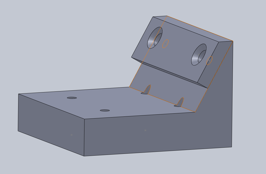
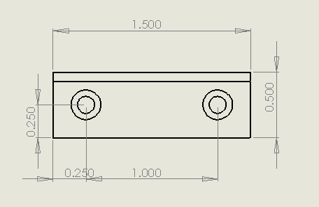
* Noe came and talked to me about fabricating a micro-indenter tool holder for Paul. He sent me some CAD files to check out, and we went to talk with Craig Milroy about using the PRL for the job--the Thermo shop doesn't have angle blocks or a y-axis read, so it saved a lot of trouble using one of the PRL Bridgeports for the milling. The part turned out well and I was able to finish all of the critical machining in one long afternoon with just some holes left to mill and tap. I finished the part in the Thermo shop, then grabbed some socket cap screws from the physics store. The CAD model of the part:
Week 4: July 6 - July 8
* Short week: holiday on the 5th, left a day early to head back home to LA for a week.
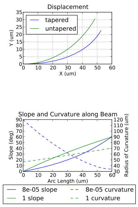
* I spent almost my entire time this week writing a new script called slopeArcDisp.py (which took a little bit of time) and then debugging the axes, legend, etc (which took forever). The script plots tapered and untapered beam profiles in axes object (top), and then the corresponding slope and curvature functions on another axes object (bottom). Plotting the slope and curvature functions on the same plot required two different y axes and the use of the twinx() function.
Getting the twinx() command in python to work was particularly challenging; for the longest time I could only get one of the two axes to format correctly, and the other axes object was out of whack. Dan finally found the problem--it turns out that the twinx() function doesn't like to have either of the axes have a set aspect ratio. Dealing with the legend was also very tricky. Python uses different reference frames for different objects. For example, with a set of axes, you specify their location with regard to the bottom left hand corner of the figure, and the size parameters are input as (left, bottom, width, height). Each of these parameters is a ratio, so if you made the "left" parameter equal to .1, it would mean that the left hand side of the axes was lined up 1/10 of the way from the left side of the figure. With the legend object, the reference is with the bottom left hand corner of the axes object. This creates a huge headache when you're trying to get things nice and pretty. In the end, it worked out though. Here's a plot from the script:
* I also put together some of the laser cut pieces for the controller box. I'm concerned that .75" won't be enough height inside the controller box to house the electronics, especially the 90 degree molex connector that I'm going to get from Jameco, but it should be easy to change the height and re-cut the box should I need to. I also might make the top piece out of thicker acrylic to allow more space for the fasteners that will be holding it down. An interesting note: if you raster a piece of acrylic over a large area, the acrylic will warp and go all concave on you.
* Also been reading "Brunelleschi's Dome." Highly recommend it to anyone, super fun easy read, some really cool mechanisms.
Week 3: June 28 - July 2
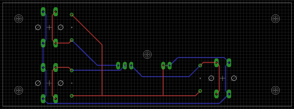
* Cadded up the schematic for Noe's control board and sent it out to be printed. Eagle's parts library is incredibly disorganized and it took me forever to find the parts I needed. I did get a nice introduction to Digikey, Jameco, and Mouser catalogs, which are pretty amazing resources. I finally got the part numbers for the buttons and molex connectors that I want, and then scrolled through the parts pages in Eagle until I found the CAD for them. The final layout:
* The reason for the long PCB board is so that it can fit into the super awesome controller box that I'm making. I've been getting familiar with the Epilog laser cutter in the LFL, and I learned that you can create an image in Illustrator with different layers and then save it as a PDF. You can then open this PDF on the LFL computers in CorelDraw? and print the image to the Epilog layer by layer. I had one layer for rastering and one for vector cutting:

The box is going to be 5"x2"x.75" with a hole for the wires in the back. Just like a good old nintendo controller. I'm sure it will bring Noe back to the glory days.
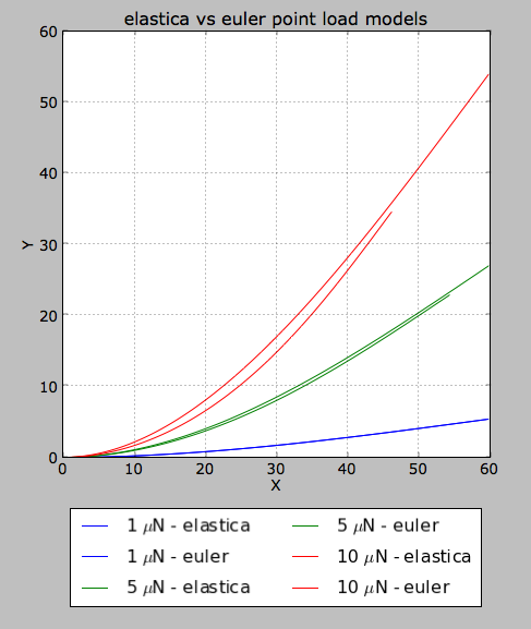
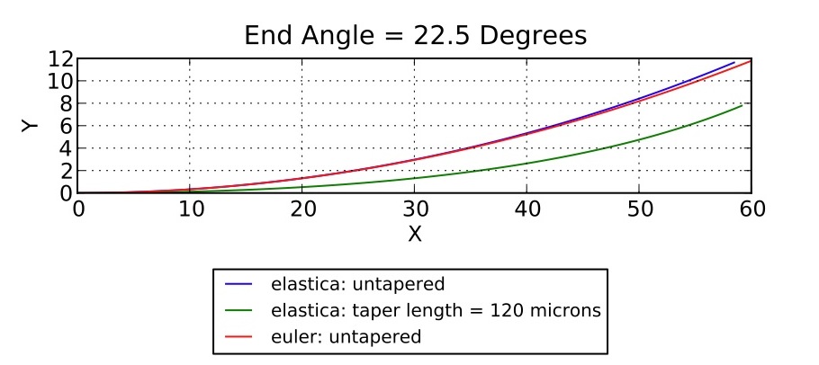
* Using bits of my "testCode.py" code for plotting untapered vs tapered elastica and euler models, I wrote a separate piece of code endAngleSweep.py (and also pointLoadSweep.py) that takes a single untapered beam and plots both Euler and Elastica models on the same graph. The code produces two plots: one for a point load condition and one for a end angle condition. This particular piece of code caused some headaches with formatting of axes within the created figures, so I now know a lot about these python objects. I also tried to incorporate dictionaries and some cool python functions like zip() and enum(). I think that in the end the code got a bit over-stylized, and I'll definitely try to take it easy on the next script I write so that it's a bit easier to follow. Here are some plots from the code:

* I also modded this code a bit so that it creates a bunch of images for increasing endAngle/pointLoad conditions which I then compiled into a video. This was pretty much just for fun--the formatting is quick and dirty, but it's pretty interesting to watch. You get a good sense of how the euler model of beam deflection fails at larger angles of deflection:
 Copyright &© by the contributing authors. All material on this collaboration platform is the property of the contributing authors.
Ideas, requests, problems regarding TWiki? Send feedback
Week 2: June 21 - June 25

- Wrote a script called "testCode.py" that compares Euler and Elastica models for beam deformation. The Euler model makes a small angle approximation, and is therefore unsuitable for large beam deflection. By comparing a small angle deformation Euler model to our other models, however, we get some idea about whether or not we're on the right track. The Elastica model is an exact model of beam deflection, and is accurate no matter how large the deformation. testCode.py plots an Elastica model for both a tapered and untapered beam, as well as the Euler model of an untapered beam. It produces two figures--a figure of the three beam models deformed under a specified point shear load, and a figure of the three beam models deformed to a specified angle at the end of the beam. Below is the plot for the end angle condition:
- Read the modeling portion of Dan's thesis paper and figured out how the Elastica model works.
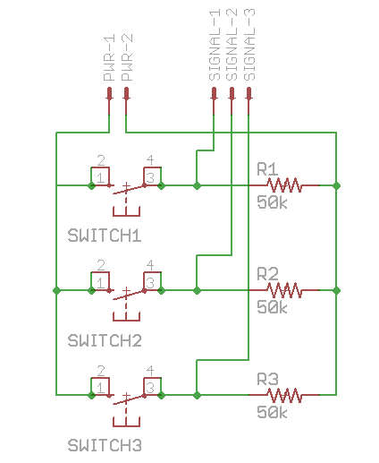
- Learned the basics of Eagle, a CAD program used in designing PCBs. I've been tasked with replacing the stage controller in Noe's experiment setup--right now it's a bunch of buttons set into a scrap piece of masonite and haphazardly soldered to some resistors and molex connectors, with part of a RadioShack? box scotched taped to it to prevent shorting. I'm going to CAD up an printed circuit board with space for some new buttons, molex headers, and resistors that we'll solder in later. My first Eagle PCB board project, though is much simpler: a convenient, simple, well-supported proto-board for Dan. We're using a CAM processor that Dan found on SparkFun? .com, and BatchPCB? .com for printing. Below is an image of the CAD from Eagle:
- While playing with the CAM files from the protoboard, found a really cool Gerber file viewer. Just feed it a zip file with your Gerbers and it displays them instantly: CircuitPeople Gerber Viewer.
- Checked out the lab, went to the LFL and saw the small laser cutter, new CNC machine, and other tools. Hopefully I get to play with (or help with) the CNC machine -- I've only used Haas mini mills and VF0s, and I think it would be cool to try out some different hardware. Trying a new CAM software would be cool too, since I only have experience with GibbsCAM? . There was also an interesting silicone casting setup under the fume hood that I wouldn't mind checking out. Maybe I can tag along when the next microwedge arrays are being cast.
- Dan introduced me to a ton of new software -- I've learned a lot already about Python, especially regarding syntax. I got some basic instruction in Git and using GitHub? as version control, which will allow Dan and I to simultaneously be working with the same code on different "branches", and then merge the versions into a working main "branch". This is how a lot of open source software gets developed, although it seems that users are generally split between Git and SVN (or something similar). The main difference, as far as I can tell, is that Git allows for a user to quickly and inexpensively create new branches of code from the main repository (I'm still a bit hazy on the details). I also learned to navigate the terminal for the first time. These new languages are going to take a bit to get used to, but python and git seem like amazingly powerful tools.
- Brushed up on my ODEs a bit, and learned the syntax for solving ODEs in python. It took me several tries before getting my head wrapped around it, but I took some solid notes so that I won't forget.
- Started reading Exact Constraint: Machine Design Using Kineamtic Principals by Blanding. This may not be necessary any more -- Dan's experiment setup is busted, so adding a sixth degree of freedom to the rig is probably not going to happen. The book is really interesting, though, and gives some useful graphical methods for cheap and extremely accurate constraint and adjustment. I love machining, and I'm pretty sure that some of the techniques described in this book will be useful for fixturing in the future. I also got my hands on Brunelleschi's Dome by Ross King. Haven't opened it yet, but plan to soon.
- Went to Wes' thesis defense and learned about friction in MEMS devices.
Ideas, requests, problems regarding TWiki? Send feedback