new web: http://bdml.stanford.edu/pmwiki
TWiki > Haptics Web>StanfordHaptics>VibrationImplementation (01 Sep 2010, KristenLurie)
-- MihyeShin - 25 Jun 2009
 X-axis indicates digital signals from XPC, and Y-axis is for output amplitude of square wave.
Through above circuits, more than 4 vibration motors can be used for experiments, although XPC has 4 analog outputs. Moreover, we could control amplitude of wave to give subjects effective feedback.
X-axis indicates digital signals from XPC, and Y-axis is for output amplitude of square wave.
Through above circuits, more than 4 vibration motors can be used for experiments, although XPC has 4 analog outputs. Moreover, we could control amplitude of wave to give subjects effective feedback.
 3) LM324 operational amplifier
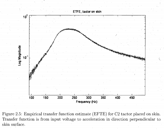
C2 Tactor ETFE
ETFE from Jason's thesis:
Implementing Vibration Feedback
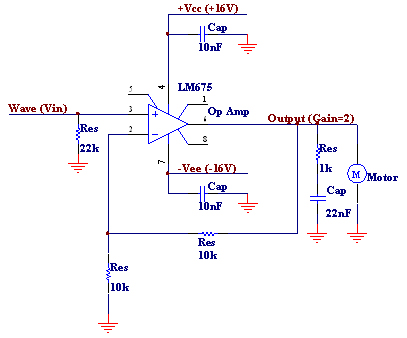
A-1) Electrical Schematic Design _ Analog inputs
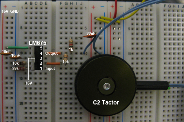
A-2) Circuit _ Analog inputs
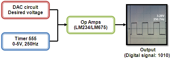
B-1) Electrical Diagram _ Digital inputs
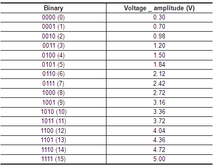
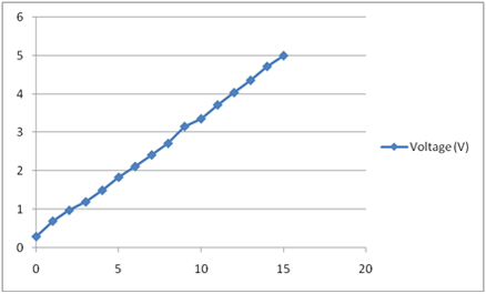
B-2) Result _ Digital inputs
Output Amplitude changes according to input digital signals.
X-axis indicates digital signals from XPC, and Y-axis is for output amplitude of square wave.
Through above circuits, more than 4 vibration motors can be used for experiments, although XPC has 4 analog outputs. Moreover, we could control amplitude of wave to give subjects effective feedback.
C) Specification
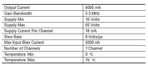
1) C2 Tactor vibration motor: http://www.eaiinfo.com/Tactor%20Products.htm Recommended Drive: Sine wave tone bursts 250Hz at 0.25A rms nominal, 0.5 A rms max for short durations. 2) LM675 operational amplifier
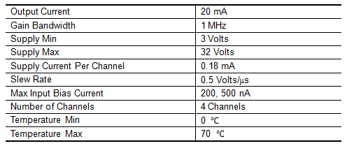
3) LM324 operational amplifier
Ideas, requests, problems regarding TWiki? Send feedback