new web: http://bdml.stanford.edu/pmwiki
TWiki > Haptics Web>StanfordHaptics > HapticsForGaitRetraining > SystemImplementation > PagerMotors>SolidWorks (28 Aug 2010, KarenNesbitt)
SolidWorks
1. Make part you want to be cut out of the CNC (the positive) in Solid Works2. I found using pro-E to assemble the wax block confusing, and just used Solid Works
3. File > New
a) Assembly4. Select your initial part you made in Solid Works from Part/Assembly to Insert (image)
a) Double click the part once visible to put onto workspace5. On the Insert Components dropdown select New Part (image)
a) Click the grey area workspace to accept this new part (a check mark appears next to the cursor until you do so)6. Your new part currently has the name "Part2^Assem1", right click and rename it something different, for example wax_block (image)
a) Note: don't name anything with spaces - although in Solid Works it does not matter, your part will not be accepted in pro-E7. To view the plane that you want to cut into, Click the View Orientation drop down and select Normal To (link)? - A
a) Holding down the middle cursor you can rotate your original part to find the face you want to select (will appear orange when cursor goes over it) (image) b) Hit Enter and it will orientate the view (image) c) SAVE!!!!!!!!!!!!!! (saving internally is okay)8. Click on wax_block by clicking on its name and click Edit Part (image) 9. Zoom out so you can create the needed 304.8 mm x 304.8 mm wax_block part 10. In the Sketch tab, click Corner Rectangle (LINK)? - B
a) Select a plane to draw your rectangle onto (needs to be the same plane you selected when you viewed normal to your original part it helps to zoom into your part and rotate it a little to ensure you get the right plane) (image) b) Click the View Orientation and select Normal To view in the plane you will be drawing in (link)? B11. Draw a rectangle with your part in the middle
a) Click Smart Dimension Option in the Sketch tab (link)? C b) Put your cursor over one edge of the rectangle, and it will appear orange (image) . Click it and move your cursor to the opposite edge (image) c) Clicking the second edge will give you the current dimension you marked (image) . Click anywhere near the line again and a modify window will pop-up - enter 304.8 mm (12 in),the size of the wax blocks (image) d) Repeat this for the other opposite sides of the rectangle12. You now want your motor part to be in the corner of the wax_block part, with the end for the cords along the edge. To do this:
a) First, make sure you are viewing it normal to the correct plane. Click the Normal To icon again to ensure (link) B b) Still in Smart Dimension, first highlight/click the end of the motor part, which will be aligned with the edge of the block (image) (image) . After clicking the green check your motor part will automatically move to the edge of the wax_block (image) c) Now you have to align the side of the motor part. In Smart Dimension still, click a blue edge of the rectangle and click the center of your motor part - it should appear as an orange dot when your cursor is over it (image) d) Give at least a 15 mm clearance between your motor and the edge of the block ~ half the width of your motor part + 15 mm (image) e) Press the green check mark, and all sides of the rectangle should be black (this means it is fully defined) f) SAVE!!!!!!!!!!!!!!!13. Now that you have made the 2D Sketch of your wax_block you must extrude it.
a) Click the Features tab and then click Extruded Boss/Base (image) b) Pressing down on the center mouse button, rotate your assembly so that you can see a side view of your parts. If the yellow extruded box does not cover your motor part (image) , click the Reverse Direction button on the left side of the screen (image) c) Ensure that the dept of your wax_block is larger than the depth of your motor part (image)14. Click the Green Check icon in the upper right corner of the workspace (image) and again the Exit Part icon in the upper right corner of the workspace (image) 15. Click the Normal To icon again. 16. SAVE!!!!!!!!!!!!!!! 17. Now we need to create multiple copies of your motor part. To do this:
a) Click your part on the left window side tree and select the Edit Part icon for your motor (image) b) Click the Linear Component Pattern located in the Assembly tab (image) c) Click the side of the wax block you want to make the linear pattern along - in this case one that will keep the edges lined up, highlighted orange (image) d) On the left hand side the settings should read 50.00mm distance, and 1 number (image) . Change this to fit the correct number of motors you want, with a respectable distance between each, ex: (image) e) Your pattern may be going off the wax_block (image) . To fix this, click the Reverse Direction Button (image) and the problem should be fixed. Make sure all your copies fit on the block (image). f) Click the Green Check icon in the upper right hand corner (image)18. Now we need to take out (create a cavity) of the motor parts we just copied. To do this:
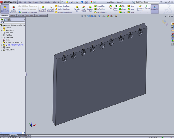
a) Go into Edit Part for the wax_block (image) b) Now go to Insert > Molds > Cavity (image) c) On the tree in the workspace expand the LocalPattern? 1 and select all copies and your original part should be highlighted bright blue (image) d) Click the Green Check icon in the upper right hand corner of the workspace (image)19. Your assembly is now complete (image). 20. SAVE!!!!!!!!!!!!!!!!!!
21. Open the Wax Block Part (image) 22. SAVE PART AS STEP FILE!!!!!!!!!!!!!!!!!!
a) A messeage will pop-up, click 'OK' (image) b) Save your part as a STEP AP203 (*.step) file (image)23. Import into pro-E and follow tap-file creating tutorial - http://bdml/twiki/bin/view/Manufacturing/ProETutorial (Start at "Beginning A Manufacturing Assembly" Section) -- KarenNesbitt - 27 Aug 2010
Finished Assembly:
Ideas, requests, problems regarding TWiki? Send feedback