Beam Scaling Results
See MachineScalingAssignment from ME21N? for more backgroundProcedure
April 26 MarkCutkoskyWe tested several beams of different sizes until they broke. The beams were clamped to a table top and loads were applied with a standard spring scale. The scale was first calibrated by handing two 1.5L bottles of water from it. The first beams included some square and rectangular beams of 15x15mm, 19x19mm and 15x27mm. Unfortunately, the last of these beams broke prematurely at a knot in the wood. The remaining two broke more or less as expected but did not give enough data to check scaling. We obtained better results with a set of round dowels of the following dimensions:
| Scale factor | Diameter (mm) | Length (mm) | Breaking load (Kg) |
|---|---|---|---|
| 1 | 5 | 236 | 0.5 |
| 1.2 | 6 | 283 | 1 |
| 1.6 | 8 | 378 | 1.5 |
| 2.4 | 12 | 566 | 3.9 |
| 3.6 | 18 | 850 | 6.5 |
Results
A plot of the results is shown below. I took the 4th dowel as a representative sample (big enough to get a reasonably accurate reading of the force) and plotted curves for linear, squared and cubed scaling, passing through this point.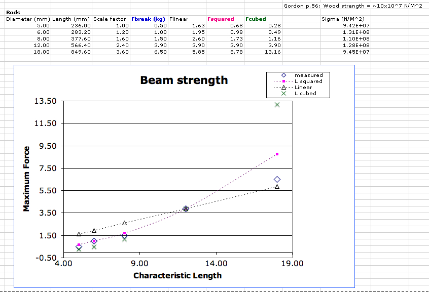
Discussion
Galileo wrote that the strength of the beam should scale as the square of the size. That's the good news. The bad news is that the applied load (for example the weight of the stone block you are lifting) increases as the cube of the size. A nice discussion can be found in one of the ME21N assignments. Galileo did not have modern beam theory, stresses and strains to work with, but his basic scaling arguments are sound. What happens if we apply beam theory? Looking in the reader from Gordon (p. 242), we see that for a beam, the maximum stress is at the top or bottom, and can be computed as where M is the moment (Force x lever arm in our case), y is the distance from the central or neutral axis to the top or bottom surface (half the diameter in our case) and I is the moment of inertia which, for a circular cross section, is
  .
Therefore we have
.
Therefore we have  . The force should be in Newtons (1 Kg = 9.8 N) and the length l and diameter d should be in meters, giving the stress in units of
  . This is a very low pressure, so people usually use megaNewtons per meter squared (
  ). The actual values of the stress are computed in the spreadsheet above as sigma, using the applied forces, lengths and diameters.
 - How do these maximum stresses compare with published data on the typical strength of wood? Look on Gordon (p. 56) where he gives some typical material strengths.
Ideas, requests, problems regarding TWiki? Send feedback