On this page... (hide)
1. Gumstix Overview
The Gumstix Overo Water computer-on-module (COM) puts laptop-like computing power on a chip the size about the size of a stick of gum, making it perfect for computation heavy embedded applications.
The Overo Water COM boasts a processor speed of 720 MHz, 512 MB of RAM, and runs a full Linux OS.
To get started with the Overo Water COM, you need a breakout board to access and interact with the actual computer.Various premade breakout boards are available for purchase from Gumstix, and have ports for keyboards, monitors, and other peripherals. Specifications are also available if one is motivated to design their own breakout.
2. Creating a bootable Micro-SD card
To use the Gumstix COM, you need to create a bootable micro-SD card that contains the operating system. Creating a bootable Micro-SD card includes partitioning and writing images. There should be at least two partitions, one for boot files, and the other one for root file system.
2.1 A Quick Creation of a Bootable Card
- Go to Sakoman's daily GNOME builds, scroll down, and download the script "mksdcard.sh"
- Make the script executable by doing the command line:
$ chmod +x mksdcard.sh
- Execute the script by typing:
$ sudo ./mksdcard.sh /dev/<your sd card device name> beagleboard gnome
- When the script completes it will indicate whether the card creation was successful or not (and why).
2.2 Manual Creation of a Bootable Card
- Use the command "df" to see the device name of the SD card.
- Unmount the card by typing:
$ sudo umount /dev/<card name>
- Calculate the card size and determine the number of cylinders:
$ sudo fdisk -l /dev/<card name>
- Partitioning the card:
$ sudo dd if=/dev/zero of=/dev/<card name> bs=1024 count=1024
$ sudo sfdisk --force -D -uS -H 255 -S 63 -C <# of cylinders> /dev/<card name>
128,130944,0x0C,* enter, and 131072,,,- enter, and 0,0,0, enter, and 0,0,0, enter, answer y to complete the partition.
- Formatting the card:
$ sudo mkfs.vfat -F 32 /dev/mmcblk0p1 -n boot, if mkfs.vfat is missing, do $ sudo apt-get install dosfsutils, and try again.
$ sudo mkfs.vfat -F 32 /dev/mmcblk0p1 -n boot
- Mount the partitions of the card:
$ sudo mkdir /media/{boot,rootfs}
$ sudo mount -t vfat /dev/mmcblk0p1 /media/boot
$ sudo mount -t ext3 /dev/mmcblk0p2 /media/rootfs
- Installing the images:
$ sudo cp MLO /media/boot/MLO
$ sudo cp u-boot.bin /media/boot/u-boot.bin
$ sudo cp uImage /media/boot/uImage
$ sudo tar xaf roofs.tar.bz2 -C /media/rootfs
$ sync
- Unmount the card for use:
$ sudo umount /media/boot
$ sudo umount /media/rootfs
- U-boot environment refresh:
# nand erase 240000 20000
# reset
3. Pinto-TH Breakout board
We are using the Pinto-TH breakout board, which is essentially as basic a board as you can get from Gumstix. The Pinto-TH breakout has a DIP style pinout, making it desirable for prototyping applications. It has a USB A/B port for USB OTG (On-The-Go) communications. USB OTG means that the device can act either as a peripheral or host. For more information on USB OTG, Wikipedia is always a great starting point.
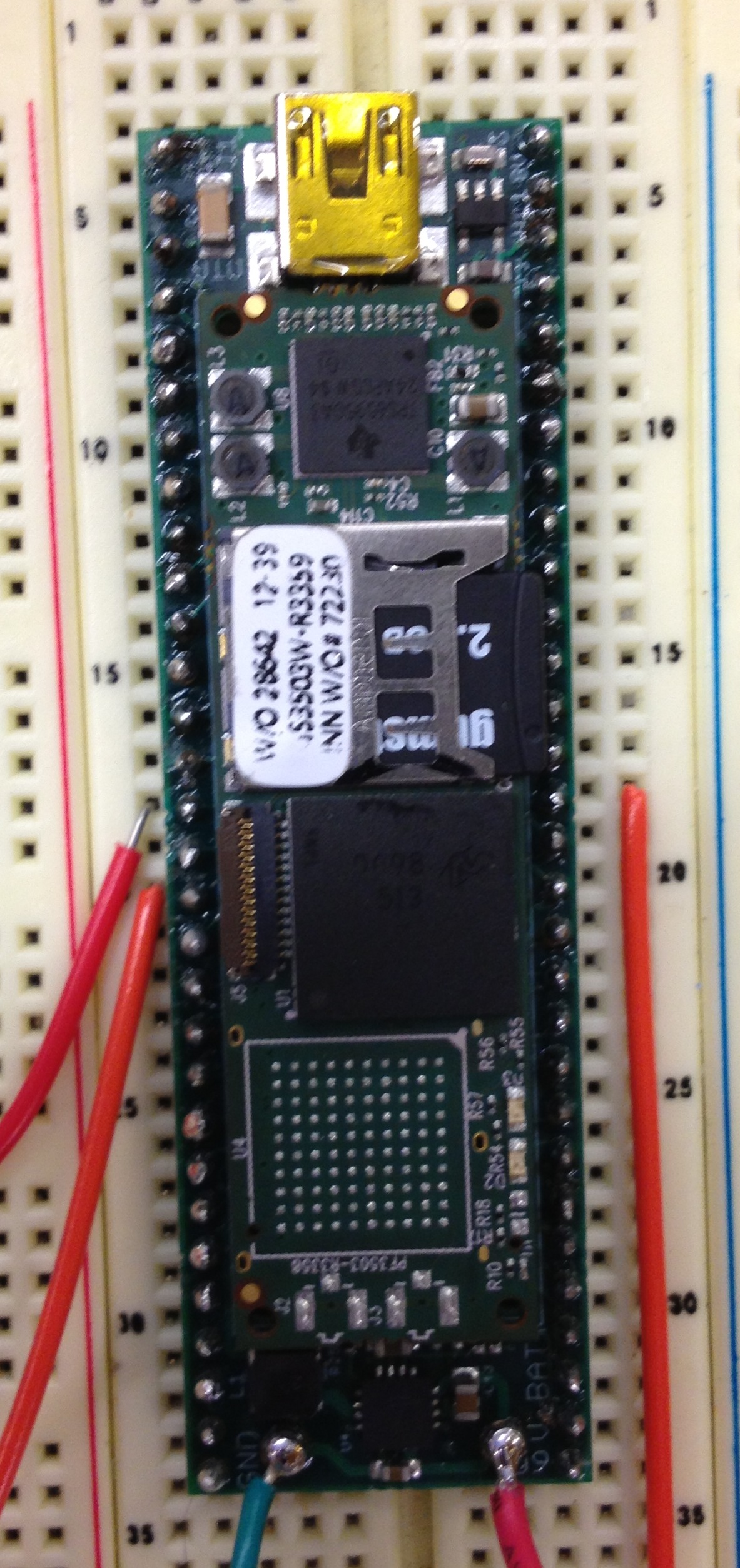
Our Pinto lodged in a breadboard.
The pinout for the Pinto-TH board is shown below. This is an unofficial pinout (there doesn't seem to be any official ones), so the pin numbering and labels may different if you look other places online, but this pinout seemed to be the most logical based on publicly available schematics and Eagle files.
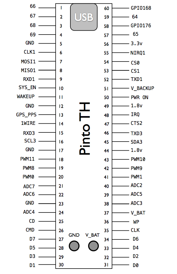
Our unofficial pinout for the Pinto-TH board.
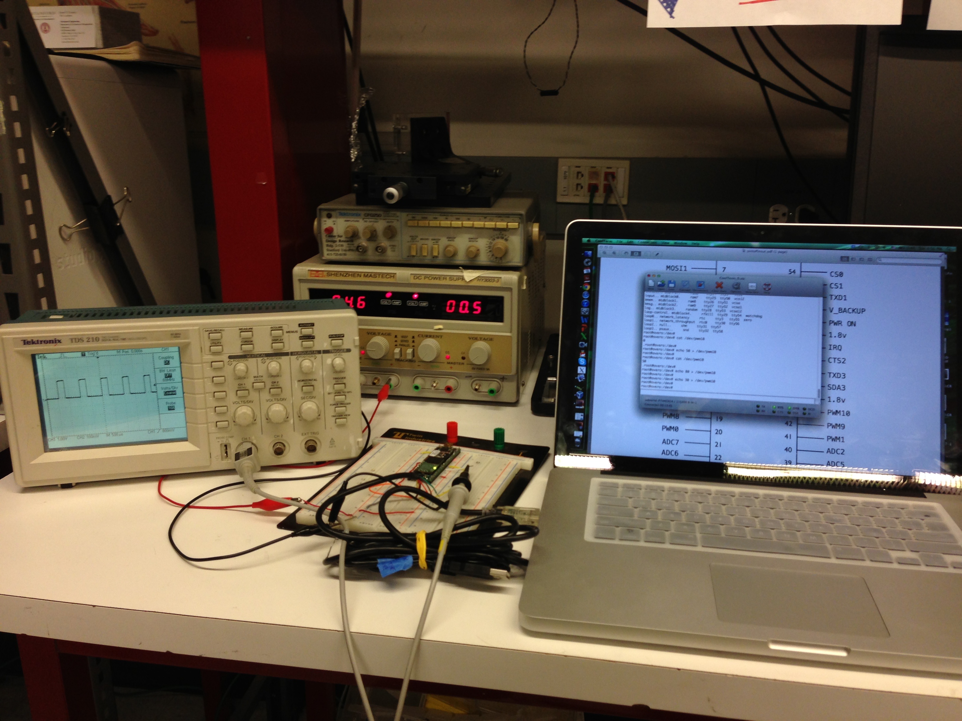
4. Communicating with the Pinto-TH breakout
Because the Pinto doesn't have plugs for a monitor or keyboard, we need to interact with the COM via a serial connection on another computer. The serial connection is broken out to UART3 on the Pinto board (pins 46 and pin 15, for TX and RX, respectively). The serial pins on the board operate on a 1.8v protocol, which is unfortunately fairly uncommon as far as serial protocols go. To connect to a standard computer, we need a device to translate these 1.8v serial signals to a USB protocol (which operates on a 5v protocol). Cables like the ones here can be purchased here.
To establish a serial conenction with the COM, you'll need:
- a terminal emulator, like CoolTerm on OSX or PuTTY on Windows. There are also ways to establish a serial connection directly through a UNIX terminal.
- a 1.8v USB-TTL serial cable
- a 5v power supply
Plug the USB end into your computer, and wire up the other end as:
- Black (GND) ---- GND (pin 17)
- Yellow (RXC) <-- TXD3 (pin 46)
- Orange (TXC) --> RXD3 (pin 15)

Both ends of the TTL-USB cable.
Be careful- all of the different voltage level cables (1.8v, 3.3v, 5v) look exactly the same! But if you use the wrong voltage level, you might fry your board. All the necessary hardware is embedded in the cable.
The arrows indicates the direction of information flow for the information lines.
In your serial emulator, put your settings at
- 115,200 Baud
- Flow control: none
- Data bits: 8
- Parity: none
- Stop bits: 1
and make sure the correct virtual serial port is connected .
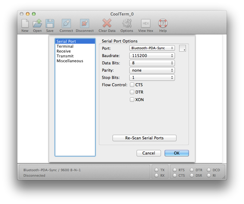
'What you should see setting up CoolTerm on OS X. Note the correct serial port has not been selected.
Now hit connect! Once you turn the Gumstix on, you should see text streaming across your terminal. Anything you type in the console will get fed directly to the COM. The COM should now be detailing its boot-up process.
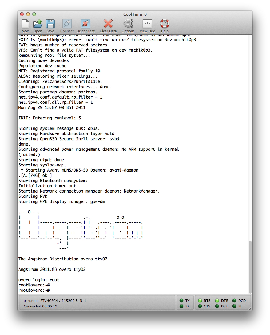
'What you should see while the COM boots.
4.1 Toggling a GPIO pin
So now we actually want to make a pin change states. To toggle GPIO (general purpose input-output) 168 (pin 60), type this into the terminal:
 root@overo# echo 0 > /sys/class/gpio/gpio168/value
 root@overo# echo 1 > /sys/class/gpio/gpio168/value
That's it! Depending on what bit you put after echo, the pin will go either low (GND) or high (1.8v).
4.2 Shutting down the COM
Before disconnecting power to the COM, use the command
root@overo# shutdown now
and wait for the notification that it's safe to turn it off.
5. Onboard C/C++ Compilation For GPIO control
As long as your installation of Linux includes the gcc/g++ packages, compiling and executing C/C++ code is virtually identical to any other platform. That is, given some file test.c, you can just do
 root@overo# gcc test.c -o run.o
 root@overo# ./run.o
Or for a C++ file:
  root@overo# g++ test.cpp -o run.o
  root@overo# ./run.o
5.1 Controlling GPIO Pins in a C Program Using "System" Command
While there's definitely an interface for controlling the GPIO pins directly through C, the best we can do right now is have our C code just pass commands to the UNIX command line. For example:
 #include <stdio.h>
 //This code toggles GPIO168 at approx 10 Hz.
 int main(){

      int state = 0;

      while(1){

           if (state)
              system("echo 0 > /sys/class/gpio/gpio168/value");
          else
              system("echo 1 > /sys/class/gpio/gpio168/value");

          state = !state;

         int ii;
         //wait a bit
         for (ii = 0; ii< 10000000; ii++){};

     }

 }
5.2 Controlling GPIO Pins in a C Program Using File Operations
Each time we use system command, a new shell process will be called. So we try to use file operations to do the same thing as "echo" and "cat". The following code is to flash the GPIO144 pin.
 #include <stdio.h>

 void gpio144_set_value (char n);

 int main()
 {
	int i;
	int status=1;
	while (1)
	{
		if (status == 1)
		gpio144_set_value ('1');
		else
		gpio144_set_value ('0');
		status=!status;
		for (i=1; i<10000000; i++)
		{}
	}
 }

 void gpio144_set_value (char n)
 {
	FILE* gpio144value;
	gpio144value=fopen("/sys/class/gpio/gpio144/value","w+");
	if (gpio144value < 0)
	{
		perror("Could not open GPIO144");
		exit (1);
	}
	fputc(n, gpio144value);
	fclose(gpio144value);
 }
5.3 Controlling GPIO Pins in a Shell Script
There is another way to control the GPIO pins using the Shell Script instead of C Program, which might use less processes of the microcontroller. (Each "system" function would call a new shell process.) Again this might not be a generic nor the best way to control GPIO, we are looking for a more generic driver.
#! /bin/sh
i=1; s=1; while [ "$i" -gt 0 ]; do
    if [ "$s" == 1 ]
    then
        echo 0 > /sys/class/gpio/gpio144/value
        s=0
    else
        echo 1 > /sys/class/gpio/gpio144/value
        s=1
    fi
    counter=1
    while [ "$counter" -lt 5000 ]; do
        counter=$(($counter+1))
    done
done
6. GPIO Driver and GPIO Event Driver (Interrupt Driver)
6.1 GPIO Driver
As mentioned above, the C onboard compilation is a simple way to toggle the GPIOs. However, if the functionality of a certain GPIO is to be changed, we have to modify the source code and run it again. A more generic and convenient way to do so is to build a driver and load it. In this way we can use it whenever we want and just do some file operations without relying on command lines. For a user GPIO driver, Dave Hyland has a perfect example here, and he also provided an example of user C program to talk with the driver. But each time we want to change the state of the a GPIO we still have to run the application program again. Thus for the user GPIO driver and the sample application program, it's just a more generic way to deal with GPIO output without significant improvement for convenience. The specific usage for this driver with the application program is indicated as the followings.
LD_LIBRARY_PATH=~/GPIO-DRV/lib
export LD_LIBRARY_PATH
./gpio
The options are:
6.2 GPIO Event Driver
However, for the GPIO event driver it's a lot better. The driver written by Dave Hyland can be found here, where he also explained how to use the driver and the application program. With this driver, we just need to notify the system whatever GPIO we want to monitor, and after that we can easily get the interrupt signal data from the file /dev/gpio-event with the command cat. And because this is driver, the functionality is always there once we load it. Yet for a simple C code program a infinite loop is required so that we cannot do other things while the program is running.
Note that to install a driver (.ko file) we just need to type the following in the command line:
overo# insmod <driver_name>.ko
6.3 Writing A Simple GPIO Interrupt Driver
The GPIO Event Driver is kind of complicated to read and modify. If we do not need so many functionalities but just a simple digital input monitor (interrupt), we can write a simple driver ourselves. The followings are some outlines for writing a driver for interrupt on GPIO110.
static irqreturn_t gpio_irq_handler(int irq,void *dev_id)
{
    <perform code here>
    return IRQ_HANDLED;
}

static int __init gpio_irq_init(void)
{
    gpio_request(110,"gpio_trigger");
    gpio_direction_input(110);
    //set_irq_type(gpio_to_irq(110), IRQ_TYPE_EDGE_RISING);
   int gpio_irq= gpio_to_irq(110);
   int ret = request_irq(gpio_irq, gpio_irq_handler, IRQF_TRIGGER_FALLING, "gpio irq handler", gpio_irq_handler_id);
    if (ret){
       printk("gpio interrupt request failedn");
       return -1;
    }
    else{
       printk("gpio interrupt request succeededn");
       return 0;
    }
}

static void __exit gpio_irq_exit(void)
{
    free_irq(gpio_to_irq(110),gpio_irq_handler_id);
    gpio_free(110);
}

module_init(gpio_irq_init);
module_exit(gpio_irq_exit);
MODULE_AUTHOR("Hao Jiang");
MODULE_DESCRIPTION("A module for testing gpio irq");
MODULE_LICENSE("Dual BSD/GPL");  //TBD
7. Generating PWM signals
Basically there isn't any PWM driver built inside the Linux OS (Angstrom), and there maybe two ways to generate PWM using the Gumstix with OMAP35xx microprocessor. The first way is to use the command line to write directly to relevant registers to adjust the frequency and duty-cycle. The second way is to build a PWM driver, compile it natively on board or cross-compile it using cross-compiling tools like OE, and load the driver on board. We will discuss the compilation part later. There is a great article about generating PWM on Gumstix here, it's really detailed, and the followings are brief summaries.
7.1 Command Line
NOTE: The devmem2 procedure won't work with kernel 2.6.39 or greater. Because we are using a kernel above 3.0, we didn't use this method, but it's still the simplest way.
- Disable the timers completely at the beginning:
root@overo# devmem2 0x48086024 w 0
- Change the PAD multiplexing to allow PWM10 off this pin instead of its current configuration as GPIO_145:
root@overo# devmem2 0x48002176 h 0x0002
- Set the frequency of the PWM signal to 1024 Hz:
root@overo# devmem2 0x4808602C w 0xFFFFFFE0
- This sets the duty cycle of the PWM signal to 50%:
root@overo# devmem2 0x48086038 w 0xFFFFFFEF
- Prime the timer counter for the first cycle. Primed with the same value as the frequency:
root@overo# devmem2 0x48086028 w 0xFFFFFFE0
- Start the timer in PWM mode.
root@overo# devmem2 0x48086024 w 0x01843
7.2 PWM Driver (Kernel Module)
The driver coding is really complicated so we used an existing driver to modify it. The modifications are done according to OMAP3 Technical Reference Manual. And the tutorial is more concise and also helpful. The following steps are assuming that we are using an OE environment, for which one can follow the instructions here to establish it. Note that this may consume about 30G and several hours, and if you are using a Ubuntu please use the 10.04 version, which has already been tested for building OE. Also please ensure that the kernel version on Gumstix MUST be the same as the OE environment you use for cross-compilation. Otherwise the driver could not be loaded on Gumstix. What we did is to use the image in the directory of /home/hao/overo-oe/tmp/deploy/glibc/images/overo to guarantee the same kernel version.
- Get the driver using git.
$git clone git://github.com/scottellis/omap3-pwm.git
$cd omap3-pwm
- If you have your OE temp directory in a non-standard location, then export an OETMP variable with the path before sourcing the overo-source-me.txt file.
$[optional] export OETMP=/<your-oetmp-path>
export OETMP=/home/hao/overo-oe/tmp
- Cross-compile the driver.
$source overo-source-me.txt
$make
- There will be a pwm.ko file in the current directory. Copy it to the SD card and boot the Gumstix with card. Once booted, use the following command to load the driver.
root@overo# insmod pwm.ko servo=0 timers=9,10 frequency=1024
There several parameters that can be tuned:
- timers: 8,9,10,11
- frequency: from 1024 to 13M/2
- servo: 0,1 corresponding to off and on respectively. When servo mode is off, the duty cycle mode is on.
- servo_min: Minimum value for servo pulse in tenths of microseconds. The default is 10000 representing 1 ms. The absolute min is 5000 or 0.5 ms.
- servo_max: Maximum value for servo pulse in tenths of microseconds. The default is 20000 representing 2 ms. The absolute max is 25000 or 2.5 ms.
- servo_start: Start value for servo pulse in tenths of microseconds. The default is 15000 representing 1.5 ms. Electronic speed controllers might prefer a 1 ms pulse. The range is servo_min to servo_max.
- nomux: Do not mux the pins for PWM usage. 0,1 corresponding to mux and no mux respectively.
After loading the driver, you can now find the pwm entry in /dev.
- If you are using the duty cycle mode, do the following to adjust an 80% duty cycle on PWM10.
root@overo:~# echo 80 > /dev/pwm10
- If you are using the servo mode, do the following to adjust an 1.5ms pulse duration on PWM9.
root@overo:~# echo 15000 > /dev/pwm9
Note that there will be a problem for kernel 3.2 that this driver cannot be removed and then rreloaded. You may have to shutdown and reboot to reload the driver. The entire process can also be done using native onboard compilation, but it requires network access on Gumstix. For native onboard compilation, please see the tutorials here. After you compile the driver, you will get a pwm.ko file, and the rest are the same.
50% duty cycle pwm signal.
8. General Purpose Timers
For Gumstix with OMAP3 microcontrollers, there are totally 12 GPTimers with mostly 32KHz clock and 13MHz system clock. As for most Gumstix breakout board there are only four GPTimers available to the userland, known as GPIO144, 145, 146, and 147, which are the same as PWM. The rest are known as internal timers. A good and generic way to start a timer and do the timing with interrupt is to write a driver. Generally the driver usually contains timer initialization and interrupt handler. Most functions used in this part can be found in the header file <plat/dmtimer.h>.
The following is an example for a GPTimer driver.
#include <linux/module.h>
#include <linux/kernel.h>
#include <linux/init.h>
#include <linux/clk.h>
#include <linux/irq.h>
#include <linux/interrupt.h>
#include <asm/io.h>
#include <plat/dmtimer.h>
#include <linux/types.h>

// opaque pointer to timer object
static struct omap_dm_timer *timer_ptr;

// the IRQ # for our gp timer
static int32_t timer_irq;

// do some kernel module documentation
MODULE_AUTHOR("Adam J Kunen <adam@kunen.org>");
MODULE_DESCRIPTION("OMAP3530 GP Timer Test Module");
MODULE_LICENSE("GPL");

// The interrupt handler.
static irqreturn_t timer_irq_handler(int irq, void *dev_id)
{
    // keep track of how many calls we had
    static int32_t irq_counter = 0;

    // reset the timer interrupt status
    omap_dm_timer_write_status(timer_ptr, OMAP_TIMER_INT_OVERFLOW);
    omap_dm_timer_read_status(timer_ptr); // YES, you really need to do this 'wasteful' read

    // print obnoxious text
    printk("Meow Meow Meow %dn", irq_counter ++);

    return IRQ_HANDLED;
}

// Initialize the kernel module
static int __init gptimer_test_init(void)
{
    int ret = 0;
    struct clk *gt_fclk;
    uint32_t gt_rate;
    printk("gptimer test: starting moudle initn");

    // request a timer (we are asking for ANY open timer, see dmtimer.c for details on how this works)
    timer_ptr = omap_dm_timer_request();
    if(timer_ptr == NULL){
	// oops, no timers available
	printk("gptimer test: No more gp timers available, bailing outn");
	return -1;
	}

    // set the clock source to system clock
    omap_dm_timer_set_source(timer_ptr, OMAP_TIMER_SRC_SYS_CLK);

    // set prescalar to 1:1
    omap_dm_timer_set_prescaler(timer_ptr, 0);

    // figure out what IRQ our timer triggers
    timer_irq = omap_dm_timer_get_irq(timer_ptr);

    // install our IRQ handler for our timer
    ret = request_irq(timer_irq, timer_irq_handler, IRQF_DISABLED | IRQF_TIMER , "gptimer test", timer_irq_handler);
    if(ret){
	printk("gptimer test: request_irq failed (on irq %d), bailing outn", timer_irq);
	return ret;
	}

    // get clock rate in Hz
    gt_fclk = omap_dm_timer_get_fclk(timer_ptr);
    gt_rate = clk_get_rate(gt_fclk);

    // set preload, and autoreload
    // we set it to the clock rate in order to get 1 overflow every 3 seconds
    omap_dm_timer_set_load(timer_ptr, 1, 0xFFFFFFFF - (3 * gt_rate));

    // setup timer to trigger our IRQ on the overflow event
    omap_dm_timer_set_int_enable(timer_ptr, OMAP_TIMER_INT_OVERFLOW);

    // start the timer!
    omap_dm_timer_start(timer_ptr);

    printk("gptimer test: GP Timer initialized and started (%lu Hz, IRQ %d)n", (long unsigned)gt_rate, timer_irq);

    return 0;
}

// Cleanup after ourselfs
static void __exit gptimer_test_exit(void)
{
    printk("gptimer test: cleanup calledn");

    // stop the timer
    omap_dm_timer_stop(timer_ptr);

    // release the IRQ handler
    free_irq(timer_irq, timer_irq_handler);

    // release the timer
    omap_dm_timer_free(timer_ptr);
}

// provide the kernel with the entry/exit routines
module_init(gptimer_test_init);
module_exit(gptimer_test_exit);
The program is very self-explanatory and we can easily modify it according to our specific timing needs. For example, if we want to use the GPTimer to realize the GPIO flashing, we just need to add some GPIO operations in the interrupt function part in the driver. Furthermore, if we want to get access to specific overflow interrupt via file operations, we can aslo add device and class initialization to the driver just like the GPIO event driver. Since the GPTimer is also used in PWM driver, we can also refer to that driver for some information.
9. Reading ADCs
Unlike the previous section, ADCs on Gumstix are not from OMAP35xx microprocessor. Instead they are from TPS65950 chip. There is already a madc driver on board that exposes the ADCs under /sys/class/hwmon. So it's easy to use the command line to read the ADCs.
Of the 16 ADCs on the TPS65950/TWL4030, 7 are available for general purpose use, ADC0 and ADC2-7. Gumstix brings out ADCs 2-7 on their expansion boards as well as an analog ground pin.
The input range of the ADC's is 0 to 2.5v, and the read from ADCs is 0 to 2500 accordingly.
For userland program using C, the following code is a good example. It's just simple file operations and doing the same thing as command lines.
#include <stdio.h>
#include <stdlib.h>
#include <string.h>
FILE *fp;
int main(void)
{
   char read_value[4];
   char adcVal2[6];
   if (( fp = fopen("/sys/class/hwmon/hwmon1/device/in2_input", "r")) == NULL)
   {
       printf("Can not open hwmon1 n");
       exit(1);
   }
   rewind(fp);
   fread(&read_value, sizeof(char), 1 , fp);
   strcpy(adcVal2 , read_value);
   fclose(fp);
   printf("nADC 2 value = %s n",adcVal2);
   return 0;
}
A more complicated and functional example is here. The theorem for this is similar to the above code.