June 24
First day in lab. After getting set up with all the equipment, we took a quick tour of the lab and heard a little bit about the projects that everyone was working on. With the other SURI members, I started off with the perching project. We worked on the experimental testing machine to try to get it to throw properly. The thrown object tended to roll forward, and after examining the contraption, we decided that the attachment between the launcher and perching machine needed to be reworked.
Andrew also introduced us to the high speed camera so we could collect data for the launch.
June 25
I wanted to get more familiar with SolidWorks and spent most of the morning working through tutorials. After getting some of the rust off and reorienting myself with it, I started working on making a larger scale landing platform sensor, which involved scaling up the original one. I was given the starting/model SolidWorks file for the original landing platform to modify to the new size. Modifying the pad to the correct dimensions took longer for me than it should have (in retrospect, it would have been a lot faster to start from scratch, as I could have finished it must faster than trying to learn how all the original parts fit and related to each other. By doing it the modification way, every change I made to one piece I had to ensure it carried through to the other pieces, and since the different pieces used different scaling references, it was a little more difficult. Although it was very valuable to learn how to modify an older part rather than just create a new part).
June 26
I finished making the SolidWorks parts for the landing platform. The actual file included a lot of work-arounds and execution could have been cleaner, but the final parts seem to work.
Going back to the perching project and working with the throwing mechanism we started the first day, we were should how to use the laser cutter. We cut out new parts for the connection mechanism to modify the thrower.
The next step is to model the perching machine. On the whiteboard, we defined all important variables as a starting point.
Since we were out of acrylic for the landing platform, after work, I went to TAP plastics to get a couple more sheets of acrylic. Tomorrow or Friday, we plan to make the landing platform with my modified solidworks parts and the acrylic.
June 27
In the morning, Hannah gave us showed us some molding and casting. The molds are for the joints in the fingers of the underwater hand. This method would be helpful for making flexible parts/components. The molds that we cast were for testing and modeling the amount of bend for various shapes of the joints.
Some notes: Generally involves mixing two substances (check the bottles to make sure that you have the correct ratio between the two). The mixture gets more viscous the longer it is out and becomes harder to mold (check the bottle to see how much time; the one we used was about 20min). Make sure to mix a lot! If using dye, use a very small amount because it is very potent. Make sure to only have filled the cup around halfway, especially if using the vaccuum to remove the air bubbles, since the mixture will bubble up and rise. When adding the mixture to the mold, it is helpful to spray the mold with [one of the supplies] to prevent the final product from sticking to the mold (spray this outside). Dispose of waste properly.
In the afternoon, we CADed and laser cut parts to modify the throwing mechanism. Since the launcher was causing the percher to hit the ground before the glass, we did some calculations to see how high we needed to raise the support beams, and the range we could afford given how much we can load the spring. Instead of making new support beams, we took components of the original and extended them so that we wouldn't have to take apart the original thrower, and we could just add to it. After cutting out the parts and building, we tested the launcher and verified that the percher now hit the center of the glass, instead of hitting the ground first. The next step is to somehow get the percher to stick: we will probably use the highspeed camera to see what is going on.
June 28
(laser cutter down, will wait to finish the landing platform/sensor). The rest of the morning was devoted to lab clean up. This helped us get to know where everything was in the lab, and what materials we had access to. In the afternoon, Alice showed us Eagle ("CAD for circuits") and gave us a quick tutorial. Some things of note: don't use 90*angles,
Afterwards, I spent some more time with SolidWorks, messing around with it more than using tutorials to see if I could make things scratch without going back to reference too much.
July 1
In the morning we went over all the different projects of the lab members so that we could start to focus on one or a few.
In the afternoon, I got started with Eliots's project with creating a foot pad for scaling up smooth walls. The hand pads should be functional and now require attachment to the feet. Instead of having separate sticky pads for the feet, it is actually advantageous to have the weight from the feet all distributed on the hand pads. Since the sticky pads work best with a higher shear force, and any weight taken off of the hands onto the feet will decrease this shear and shift the center of mass of the body away from the wall, it is best to have the hand pads and foot pads connected. Attach:footpad2.jpg Δ
As earlier researched and just intuitively from rock climbing, the hands/fingers primarily pull the body into the wall and let the body hang upward, while a lot of the force from the foot pushes into the wall. Therefore, the more load off the hands means more load on the foot so that the body is being pushed away from the wall. weWe thus want to have as much weight on the hand pads as possible, and this is achieved through attaching the footpads to the hand pads to allow the footpads to be suspended. The sticky pad is less effective when being pulled away from the wall, so we also want the center of mass to be as close to the wall as possible. If modeling the forces on the hand pads, we want the hand pads to experience the greatest downward force to outward [from the wall] force ratio as possible.
I started working on CADing a footpad to see if there is a way to optimize and quickly reproduce the shape of the footpad.
July 2
Morgan spent the morning teaching Andrew and me how to manufacture the landing pad mechanism, in case parts of the old mechanism broke and needed repair or complete replacement. The process took about two and a half hours including setting time, so it might be good to keep that in mind if the part ever needs replacement during testing. Some notes to keep in mind: superglue and accelerant are key! Try not to get accelerant on the sticking pads. Don't use scissors for cutting carbon fiber (it will splinter). Make sure the carbon fiber is attached to the component on the socket the right way so there is less friction. Some modifications included Matt's use of magnets instead of just a hook for the catching and releasing mechanism.
July 3
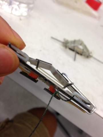
I was given a quick overview of Santhi's project. I would need to first create a container to hold the tissue. The container will have varying length components so that the user would feel tissues at different lengths. Each segment will need a redesigned locking mechanism, likely some sort of latch. The next step is to prepare the phantom tissue and test the force sensing needle through trials. I finished and laser cut the model for the climbing footpad, and then took the old prototype and reassembled everything onto the new laser cut model. This prototype will be used for testing alignment and positioning and distribution of weight. Depending on how the pad hangs, I can adjust the shape to maximize strength/minimize weight. Some quick things to note was the positioning of the foot relative to the strings: it seems that the feet might be a bit wide, causing the pad to tip over a bit at a small angle. This tilt results in more tension in two of the strings, with the third string hanging loose. I don't think it is a matter of tightening that third string: it would only exacerbate the tilt. I think that we will need to play around with the positioning of the foot on the pad.
July 5
Santhi had phantom tissue containing compartments for experimental work for testing penetration through and tactile feedback from the phantom membrane. However, the problem was in quickly altering and replacing different test variables quickly. Ideally the membranes between the tissue would be easily variable. As a result, it would be nice to have multiple compartments that attach to each other. We brainstormed methods for creating such an attachment mechanism. Through Solidworks, I worked with a locking/latch mechanism to for the compartments. I experimented with clicking locks, and different sized hinges to see which gave most secure fit given the compliance of the 3-D print material. Attach:latchCAD.jpg Δ
July 8
We started getting footage with high speed and taking data. We first took a couple highspeed shots to see what orientation seemed to maximize success rate. What looked best was the quadrotor in a "plus" position with the propellers on the top and the right. Upon analysis, the mechanism released and the rebound spring helped the quadrotor stay on the glass. We then started taking data sets of five each at four different speeds: on the release gage, these are positions 1, 3, 4, and 6. We marked the initial horizontal distance from the glass at which the perching mechanism is launched. The first speed we did not get any landing. The second speed we got very close to landing: the system engaged, however it did not stick. The third speed we ran into the same situation. And the final speed proved too fast, and it looked like the mechanism wasn't very close to landing. Since the perching was engaging, we were concerned why the mechanism didn't stick during any of the ten trials at those seemingly optimal speeds. We then found out that the string connecting the tendons of the sticky pad wore out, and the fibers were no longer pulling anything. We thus have to redo all of our data to keep the experiments consistent (once we fix the perching mechanism, to make maintain an experimental control, we need to redo all of the tests on this new mechanism). In the afternoon, I finalized the CAD for Santhi's phantom tissue casing. For hinges and moving parts, it is good to have a clearance of .2mm. In addition, based on the material we are planning to use, I was told that I could thin out the walls, since the thickness I originally had (4mm) was more than sufficient. Thus, I reduced it to 2mm thick. Some things to keep track of when editing assemblies: Re-dimensionalizing difficulty is based on how the dimensions are referenced. Try to reference a constant point or an origin. When I changed the dimensions of one face, SolidWorks didn't like what would result at the other faces because the two were interweaved. As a result, redimensionalizing took longer than expected, since I had to rebuild it comprehensively.
July 9
In the morning, I started by fixing the perching mechanism to so that we can get it to land and stick on the wall again. The string tightening the tendons had been worn out, and the sticky pads themselves had to be removed and reassembled for the sticky pads to engage. while waiting for the perching mechanism to set, we assembled a previously prepared perching mechanism to the quadrotor. After reattaching the rebound mechanism and doing a few tests, we though it would be better to use the fixed old perching mechanism, since that had already been tried and true. After reassembling the newly fixed mechanism, we had to make multiple modifications to get it to work. After a lot of troubleshooting, we ultimately tightened the tendon, thinned out the rubber band for initializing the pads, and reworked the rebound spring. Once we can get the perching mechanism to stick on the glass somewhat consistently using the launcher, we will start to systematically test the vertical, horizontal, and angular velocities that maximize success. At the end of the day, Santhi and I went over to the 3D printer to try to get the phantom tissue encasing started so that it can print overnight and be ready in the morning. In terms of orientation, it is most important to layout the parts so that vertical height is minimized (be rotating the parts, we went from an estimated 12 hours to 9 hours printing time). In addition, we were unsure of the most efficient way to align the hinges: if the hinges are upright, less wax is used to prop them up, however, vertical height is increased; if the hinges are horizontal, wax has to be used to hold them up.
July 10
We spent the morning modeling the perching mechanism. We used MotionGenesis to define all of the relations with respect to our previously defined variables. After a few attempts, we got reasonable numbers from the modeling. However, we soon realized that there was a bug somewhere in our inputs and relations, since Hao, who did some calculations by hand, had different numbers. We realized that when we varied the y-parameter, there was no change in normal force. We spent a lot of time debugging afterwards.
For the phantom tissue, the compartments were 3-d printed. The prototype demonstrated that undersized notches actually best for securing the compartments together (there was a nice click from them). Attach:phantom3DPrint1.jpg Δ Attach:phantom3DPrint2.jgp Δ Attach:phantomcompartment.jpg Δ What would be nice for convenience sake would be to have the latches include some sort of knob for quick/easy removal without having to resort to a screwdriver.
For the footpad, we continued to work modify the design and brainstorm new possible solutions. I was given an introduction to material science (something I will later do in ME80). Some quick points was that the stress related to the length and thickness of the material by a factor of three. We considered using a cantilever suspension with T-clamped carbon fiber to maintain the orientation of the foot. However, Elliot also tested having no platform, with the rope around the shoe by itself. A few of the advantages included greater structural stability, but some of the disadvantages included allowance for rolling of the ankle, and the string cutting into the foot and being uncomfortable.
July 11
I spent the morning manufacturing more prototypes of the perching mechanism to replace the broken one, and to see if there were any improvements that could be made. We discovered that the newly cut stickypads had the wrong orientation. It was good that we caught it that early so that we knew what might be wrong with the new perching mechanisms. We also were reminded that its a good idea to make sure the fibers are aligned correctly during laser cutting of the stickypad material. After we built the perching mechanisms, we tested them to see how they compared to theoretical normal force loading values, and to project how they might optimally perform. I used the pads rated (tested by us) to cling onto 450-500 grams individually (these were the best pads/measurements we got from this batch). From testing, my perching mechanism was only able to hold 75grams of complete normal force.
July 12
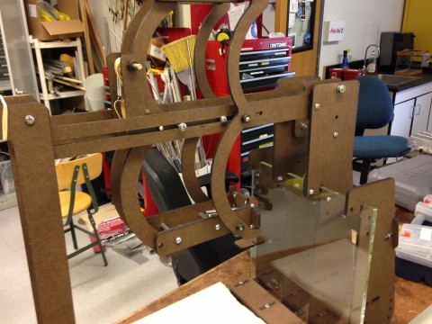
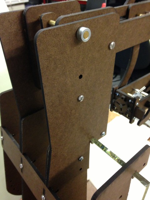
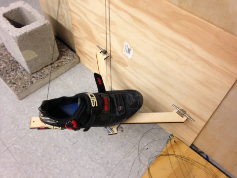
We set up the frame for glass panels for testing climbing mechanism. Most of the day was devoted to setting up all the components for a test run, rather than focusing on the footpad itself. Before we can get building clearance to climb up the glass windows, we started setting up a small scale version.
July 15
Santhi and I walked through setting up and creating the phantom tissue. We went under the fume hood just to be safe since the synthesis creates fumes (that may or may not be toxic). The consistency can be varied, which we used a 4:1 ratio for adding softener. Heating was slow to prevent yellowing. Once to tissue was made, they cut to be fit into the 3-D printed compartments. One concern was the possibility of having gaps between each compartment, which may contribute to the user/tester feeling a barrier/gap where there should not be one. One consideration was to cast the tissue directly into the compartments with them lined up all at once. We would then split the compartments and add phantom membrane in between.
July 16
We went back to the newly manufactured perching mechanisms to try to debug them. From our latest tests, even the best rated pads didn't allow a good stick (a maximum of 75g normal force was allowed for my percher, and Andrew's could get hardly any with lower rated 200-250g pads). We reevaluated the sticky pads and discovered that these had different normal/shear properties than the ones we were used to using. We thus systematically tested these pads to model their performance. We measured the adhesion force of the pads at various angles, and found that the ideal pulling angle was 7 degrees. We then calculated where the optimal pad separation distance would be based on where adhesion was maximized in relation to shear and normal. We eventually arrived at a separation distance of 12mm between the pads, vs. the original 8mm. So for my perching mechanism, I separated the pads each 2mm in either direction (For Andrews, we determined the pads were faulty/insufficient. As a result, his percher was replaced with even larger pads (sqrt(2) by sqrt(2) cm instead of 1x1 cm) to compensate for the lower rated pads.
I finished the afternoon by lasercutting fiberglass and plywood for the footpad. We plan to sandwich the plywood between the fiberglass for enhanced strength.
July 17
We tested the redesigned perching mechanisms for the different sticky pads. For the same pads rated at 450-500g in shear, I got about 140g normal force when attached to the perching mechanism. Compared to the previous 75g normal force allowance, this new configuration allowed greater adhesion, demonstrating that changing the pad distance from 8mm to 12mm was an improvement. (A reminder for why that distance is important: it affects the angle at which the tendons pull on the sticky pads, and there is a limiting return for how wide they can be versus how much normal force can be withstood).
July 18
To further enhance the perching mechanism, I recentered the pads, which were slightly off, so it seemed that one pad was holding more force than the other. Ultimately, there was little noticeable difference. The next step is to continue modeling and testing, as theoretically these new perching mechanisms should be sufficient with the quadrotor attached.
I worked with Solidworks in the afternoon for making a platform for the phantom tissue compartments. After importing the linear slide guide from Igus, I visualized a surrounding platform with aligned screw attachments. Attach:renderedfullassembly.jpg Δ
July 19
Continuing the phantom tissue project, I synthesized and casted more material, and I tried stacking the columns and adding the substance all at once. When the substance has cooled and set, I will see how this method works (hopefully the heat won't affect the 3-D printed compartment materials). I then finished up the platform and lasercut the parts for assembly next week.
July 22
After having synthesized the phantom tissue all together in the same compartment, I divided it to see how it compares to doing each compartment separately. To get more accurate measure, I will wait for Santhi to get the force sensing needle and software up and running. In the meantime, I did a few subjective haptic tests to see whether the gap between the phantom tissue could be felt, which would result in a false positive. Fortunately, it seemed that the gap could not be felt. This was probably because the gelatin tended to stick to itself, and adhesion was enhanced by using the same phantom for each column: the ridges from slicing created a kind of molded fit. Santhi and I then tested the membrane penetration with samples of aluminum, laundry sheets, and plastic wrap. Everything seemed to go as expected so far. Santhi will take the prototype and samples in for imaging.
I finished up the platform for the compartments and assembled it onto the linear bracket. Some of the screws get in the way, but I think there is a workaround for that. Here is a picture of what it looks like. Attach:phantomstandassembly.jpg Δ
July 23
I spent a lot of time trying to learn surfacing in SolidWorks. I found a few good tutorials on the web. Some of them ranged from making a speaker to making a Camaro. Attach:solidworksSurfacing.jpg Δ
Elliot and Dave found that the footpad was too wide for the set up frame and glass, so it will have to be redone. However, we did learn that the layered plywood and fiberglass was sufficient in strength with very little bending. So the footpad will need to be narrowed.
July 24
I finished the final compartments for the phantom tissue, and sent them off to be 3-D printed. They involved a combination of 2cm and 3cm compartments to be rearranged for gathering experimental data.
I also continued working on surface modeling in Solidworks, which I found to be very difficult. I tried the auto trace plug-in, which could be helpful to convert drawings into defined sketches, and eventually act as guides to make 3-D objects and complex surfaces.
July 25
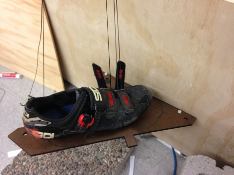
In the morning, I laser cut the newly redesigned footpad. Here is what the design looks like Attach:newfootpad.jpg Δ. It is narrower so that both feet will be able to climb over the next on the wall. Although both feet cannot be on the wall on the same level, there is now room to move one over the other.
July 26
We finished layering the footpads with five layers of ply. It seemed that the fiberglass didn't add any extra rigidity, so we stuck with the wood. Something learned was that since ply is more stable in one direction than the other, the ply needed to be cut in a way such that the grains run perpendicular between layers, so that we get greater rigidity in both directions. Attach:finalfootpadblack.jpg Δ. Elliot also added a very clean and modern black matte finish!
Santhi and I realized that the stand/casing for the phantom tissue will need to be redone since it is off center with the force sensing needle. Originally, I though that the needle was in line with the track, so it would just be a direct connection/penetration. However, when we got the needle attached, it is actually offset, so I will have to redesign the stand so that it is offset the same difference.
July 29
Andrew and I were tasked with a design challenge for the Jumpglider. Morgan had already made a mechanism to allow a motor to launch and reset the spring mechanism all without reversing direction. Attached to the body, a rod will travel across the body by way of the motor, and then once released, springs into the ground and causes the jumpglider to launch. The Jumpglider is launched at an approximate 55 degree angle, held up by a currently makeshift stand. What Morgan wants is to have the stand be attached to the jump glider and act as a kickstand, engaging and disengaging so that the jumpglider can autonomously jump, reset, then repeat. Morgan's preliminary idea was that of a kickstand that would slowly engage as the rod travels across the body, causing the Jumpglider to be at a 55 degree incline be the time the rubberband was loaded. Attach:jumpgliderstandprototype.jpg Δ Some of the initial problems that Andrew and I had was keeping the center of mass behind that of the kickstand so that the jumpglider wouldn't tip over and launch parallel to the ground. Due to the geometry and the required travel of the rod, the dimensions of this kickstand limited us and proved to be very challenging. We spent time both individually and as a group going through calculations and optimizations and rapid prototyping.
July 30
In the morning, I prepared more phantom tissue, this time with Contrast in varying ratios. Luckily Santhi was around, since after just a little bit of heat, the phantom solution began quickly bubbling. Fortunately, nothing exploded (our track record is 2 for 2 in terms of not setting fires--last time the fire alarm went off, it was actually another lab, and we just happened to be making phantom tissue at the same time). We think that perhaps it is the contrast with a lower boiling that caused the disturbance. We ended up on testing 10:1 and 4:1 solutions for contrast, since it seemed to be more trouble than it was worth. For the opacity difference the contrast provided, it introduced unwanted air bubbles. The phantom solution hardened a lot faster than before and became chunky. Also, we do not know how well the contrast mixed in, as after everything cooled, there were salt crystals still on the stir rod.
Andrew and I continued working on the jump glider kickstand. We found that if we extended the leg of the triangle formed that is closest to the ground, we could keep the center of mass of the body behind an attachment on the kickstand and prevent it from tipping over. Thus, we were given more flexibility in optimizing the lengths of the kickstand. From calculations on the board, we achieved a working and approximately optimal dimensions of 14mm for the up right edge, 17mm for the leg on the ground, and 10 from the back end of the body (so that at its fully extended length, it will be 30mm apart). These preliminary numbers will then be tweaked for design to allow different angles or an aerodynamic/flat profile. Andrew also had the idea to attach a magnet so that the kickstand would stow when not in use. Attach:jumpgliderstandprototype2jpg Δ.
July 31
Andrew and I did some experiments to model the force profile of rubberbands to allow for the jumpglider's launch. We labeled and tested different combinations, with the following conditions: The band/combo had to travel 20cm, had to start at a 2.5N tension length less than 15cm, and had to have a total extended tension (at 20cm) of around 7.5N. We were able to chart combinations and model trajectory of the jumpglider. Given the rubber band configuration (2-3 of #4), we found that to get the Jumpglider 1m in the air at 55degrees, it could have a maximum mass of 61.6g or 75.25g (respectively of the 2 and 3 configuration).
I then finished modifying the phantom tissue base to allow for the offset needle, and started working on a quick release/exchange mechanism for actually holding the needle in place.
August 1
I came in early to finish up the CAD for locking the needle down with the set screws. Attach:needleAttachmentCAD.jpg Δ. I then sent them to Santhi for 3-D printing.
After I caught something wrong in the phantom tissue base before laser cutting, I made changes and fixed it to be laser cut. This new extended base also had modifications in the slots, including a .02mm tolerance to account for the width of the laser. When I tried snapping it into place, the fit was okay, although a bit tight. Nonetheless, it worked. I also found the acrylic (this time in black) to be very brittle, and it cracked a few times. Here is the modified base: Attach:phantomBaseExtended.jpg Δ.
I finished off by dividing and rearranging our phantom tissue of various Contrast ratios, and added membrane in-between. Here is the full set up. Attach:fullassemblyphantomcompartment.jpg Δ
I also got a chance to feel what the physician would feel from feedback from the force sensing needle. It was really cool to feel vibrations under my fingertips from various surfaces. There was bending in the needle, which added noise, so we will hopefully be able to fix that.
August 2
We went to the medical center for imaging to see how the phantom tissue and experiments will look with CT. Attach:CT1.jpg Δ Attach:CT2.jpg Δ Attach:CT3.jpg Δ The contrast in the tissue did not seem to help, and it seemed to even create little bubbles in the CT. However, one of us had the idea of coating the phantom membrane with contrast, and this caused the membrane to show up very clearly. Attach:CTmembranecontrast.jpg Δ In other news, lab barbecue is next week. Some ideas? I think we are going to start a band: Shiquan plays drums, Hao and I play guitar, Andrew and Jon sing-- There is no way this can go wrong!
August 5
Santhi and I tested the force sensing needle with both the ATI and the FBG. There was noticeable difference, but for the experimental data collection, we may have to make a few modifications. We added a calibrated caliper to the set up so that it moves with the needle on the track as a way to gather data from tests with our lab mates (This method of measurement will be replaced by imaging from CT when collecting physician data). We also may need to have a teaching phase in the protocol, so the user will know what contact vs puncture would feel like. We also think dryer sheets are the best, since aluminum foil, and even latex could not really be felt.
We took the ATI/FBG feedback to gather some preliminary data. The ATI behaved and felt more or less as I had expected, with feedback coming from moving the needle through the tissue. Everytime I started and stopped, I felt feedback. However, as I went through different tissue layers, I did not feel a difference. With the FBG, I could feel moving between the tissue and the membrane. With both the ATI and FBG, I noted that resistance increased, and the effort it took to move the needle deep within the membrane/tissue became increasingly difficult. This was expected, since there was more friction the deeper I was in. With the ATI, when the needle was in deep, I could not feel anything except for when I started and stopped. With the FBG, so long as I was sensitive, I could feel or at least notice when I moved through different tissue. When we asked Mark to try it, he brought up the possibility of the difference in haptic feedback being caused by the medium the tissue/needle was in. The "pop" was more noticeable when the membrane was in air (so that it would have less structural backing from the tissue?) than when in the tissue itself. We will ask Dr. Bruce Daniels on Thursday to see what he feels and how he compares it to a normal, non force sensing needle.
August 6
In the morning, we posted flyers for our barbecue. Favorite meme: "I don't always go to the MERL BBQs, but when I do, I arrive 15 minutes early".
For the perching model, we needed to get three basic constraints in varying orientations. We had: straight perpendicular velocity, hitting the glass at an angle or having rotational velocity, and having lateral velocity. We plan to test these for the cases of landing on a level platform, on a vertical wall, and onto a ceiling. After Hao had worked on debugging the perching mechanism, and we remanufactured some parts, Andrew and I started gathering data. We first focused on a straight landing on a horizontal platform to get the landing envelope for velocity, force, etc. Hao had preliminary theoretical data, so we sprung from there. We tested at a height of 50mm, 100mm, and 150mm, for which we will use highspeed to capture the velocity, and the ATI to measure the landing force. We found that the height of 100mm worked pretty consistently. Overall, the perching seemed successful, with most of the failures coming from mechanical failure (the latch didn't hold). There were few cases where the pads themselves failed. Some notes for increasing success rate: clean pads each time, isopropyl alcohol on glass each time, and make sure the rubberband mechanism is wrapped around so that latching will more likely be successful.
Tomorrow we will try to model lateral velocity landing: how to do that? Some ideas: take the rolling chairs and roll past the force sensor while dropping the perching mechanism!? or the the same with a treadmill?!
August 7
Lab cleanup! Also, more modeling with the perching mechanism. Hao had replaced the pads and fixed a lot of things last night, and now the perching mechanism is working really well. Probably too well. We thought that pad failure would occur at a height of 300mm maximum, but we kept increasing the height and it kept working. We found that the upper limit was at a height of 700mm. Check out the video: #237/238.
August 8
Dr. Daniels came in this morning to take a look at the force sensing needle. He had some very helpful insight, and it was also very valuable to observe him use the needle. As Mark also mentioned, when using the needle with no feedback, and not on a track but directly/freehand, there is a near immediate response in the fingers down the shaft. There is a lot of subtlety that can be felt in the fingers that is hard to translate. Even going through the phantom compartments, I could feel the membrane when using the needle free hand, even when the membrane was buried deep within (around 10cm). Dr. Daniels also described that the phantom tissue we used was causing a lot of friction that he usually did not feel. The softer membrane that we used was more akin to the feeling of real tissue. He also suggested that tofu/butcher meat was a good analog. The packaging tape membrane was a little stiff, and the dryer sheets seemed to be the best. Also, it would be helpful to allow the compartments to rotate more move laterally so that they can be reused quickly without the needle creating a path.
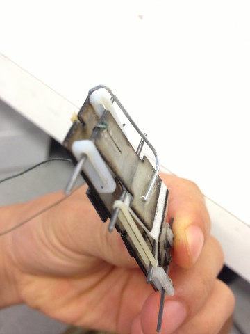
Also, the locking mechanism printed out: Attach:lockingmech3Dprint.jpg Δ.
In the afternoon, we made a Costco run to get stuff for the barbecue. Chances that the band will fall through are pretty slim. I am still hopeful.
August 9
Barbecue!
August 12
Santhi and I went to the Lucas Center to make new phantom from agar. We did not need to make too much, so the process was relatively short, although if we had wanted to make more, the process could take up to 1-2 hours. We also made more phantom from the original silicone with the 2:1 softener.
August 13
Eric gave a solidCAM tutorial. The automated machining was really cool. I also did more lasercutting/work on the footpad.
August 14
Hao, Andrew, and I continued with the modeling for the perching mechanism. We focused on analyzing the force spikes and trying to rationalize or identify each part of the plot. Since the original pads warped, we will need to replace and make new adhesive.
August 15
I collected data with the ATI to model the spring constant and damping effects of the foam. The foam behaved as expected in terms of the spring force relation, but it was more difficult to get the damping effects. The best way to get the velocity that Hao came up with was to use a motor and rotating bolt at different voltages, and then once the data is gathered, we can extrapolate the speed through analysis. However, it was tricky, since the foam kept buckling when we tried to measure this damping, which will effect the modeling characteristics. We tried making a gate, but that didn't solve the problem.
August 16
laminated and sanded carbon fiber pads for adhesive. Hao and I are continuing to work on modeling the foam damping for the velocity
August 19
solidworks
August 20
phantom update: agar good, hinge good
August 21
footpad changes
August 22
Received feedback from physicians about phantom tissue. Here are their insights for reference, as recorded by Santhi and Jung Hwa. Dr. Bruce Daniel: agar feels like normal tissue, PVC/plastisol like breast tumor Dr. Graham Sommer: PVC more convincing, agar like fat or normal liver. you could layer the two to simulate tumor Dr. Sui-Seng Tee: PVC/tape layers: realistic for going through membranes. lots of resistance. Agar: feels like a calcified lesion. cyst would feel more like membrane+agar. Dr. Lewis Shin (thyroid surgery experience): more difficult to feel 2nd membrane (although he was still successful). Should get in touch with Dr Benjamin Chung since he uses Da Vinci for surgeries. Try comparing between experienced and non-experienced user. Dr. Brooke Jefferry: in liver once you're 5-7cm in, it gets difficult to feel. On haptic feedback: [a desired] “extension of your brain into your hand.”On years of doing biopsies: “You learn to trust your feel as much as your eyes”