Summer of Sensing
A Blog by Jonathan Renslo | Summer 2013
This blog describes the work I performed and serves as a record for my experiences, musings, and insights, with the intention of documenting my time in the BDML. I hope the reader finds it interesting, and I welcome any suggestions or critiques, corrections, and any other comments. Enjoy!
June 24
Arrived, Morgan helped set up all of the logistics, hence my writing here now.
Got a lab tour and was introduced to the ongoing projects in the lab. Lot of neat stuff.
Added a hook to Matt's quadcopter launcher to adjust the tension and release the rubber bands/springs more easily.
June 25
Day 2, seems like I've been here for so long already.
In the morning, we lasercut the replacement kinematic coupling that Matt mocked up in Solidworks yesterday. Took a couple of tries to get the laser to cut all the way through. The cutter is located in the Fab Lab in the School of Education. It's awesome how many labs and cool design spaces are tucked away around here....
The process was surprisingly straightforward though. Once you have a prepared DXF (universal 2d-cad file format), all we did was import the file into Corel Draw on the linked computer, and print to the laser cutter. (also you can't forget to turn on the ventilation while it's cutting. Masonite burns)
Settings we used for 1/4'' Masonite:
- 5% speed (down from the default 8%)
- 100% power
- 5kHz
- 600 dpi
(Note: Kinematic Coupling- 6 dof, so 6 points of contact. neither over nor under constrained)
The afternoon I spent first helping Andrew make a video of a dummy quadrotor landing and perching sideways, until we called upon Hao's expertise to help complete the demonstration.
Afterward I spent some time researching how to move the Users folder for one of the computers running out of space. It appears pretty straightforward with symbolic links.
I also spent some time watching and learning from Morgan and Eric building the new double-airfoil body of the jump-glider. It's still relatively in question what shape will be optimal. Will a surface built from two NACA airfoil cross sections in the desired directions still be optimized? This raises an interesting aerodynamics question that may or may not have yet been explored. Most vehicles are optimized to move in one direction--forward--while we're trying to create a shape that will move well in two directions, on the upstroke of the jump, and gliding afterward.
One wonders if there might be a simpler solution. Maybe jumping and gliding both nose first would be better? or perhaps there are simpler ways to make the glider get a better ratio. Folding wings with a passive deployment mechanism?
Taking another look at flying fish, they apparently propel themselves with their tails along the surface of the water, not exactly jump gliding. I had trouble trying to find some empirical estimate of the glide ratio of jump-gliding animals, but Albatross have upwards of a 22:1 ratio. It puts shooting for something like 7:1 into perspective. Is it due to their 2m wingspan, or something else? Worth looking into.
Tomorrow I'll try to find some more intro into aerodynamics (like center of pressure and center of mass).
June 28
The past couple days I've still been bouncing between projects and workshops. Still a bit unsure what project I'll be working on for the majority of the summer.
I spoke with Morgan a bit more about the jump glider's wing, and possible improvements. He's been putting a lot of effort into making the body aerodynamic, but intuitively it seems modifying the wing might give more noticeable results. Morgan already wanted to make the wing stiffer with carbon sheets instead of beams holding the leading edge. He also wants to make the wings slightly angled up to create a restoring force stabilizing the flight of the craft. The string holding the wings angled up was a quick hack to create this behavior, but perhaps we might explore something more robust in the next iteration. I also suggested making the wing stiffer along the axis of motion. Flexibility in this direction might alter the angle of attack of the wings unfavorably.
I've been doing a bunch more lasercutting, of fiberglass and acrylic as well as masonite. The thicker fiberglass backing the dry adhesive is pretty nasty to cut with the laser alone. It requires several passes of the laser and clearing the residue between cuts.
Hao showed me a cool method for cutting small and fragile objects. First we made a DXF of both the outline of an object and the cut we want to make. Then, by cutting the outline in a larger sheet of acrylic, we knew where to fix the smaller piece (in this case an adhesive tile).
I also learned how to use couple other features, including the X/Y Offset on the laser cutter and the option to cut multiple times.
X/Y Offset:
- Hit X/Y Offset
- Hit Go
- Hit Pointer to turn on the red laser sight
- Move the printer head manually to where you'd like the new home position to be.
- Hit Set Home
- and confirm by hitting Reset. The head should not move back to the original home position but rather stay where you set it. If it doesn't, wait until it goes back to the "Job:" main menu and repeat, or restart the cutter.
To Print Multiple Times, simply print multiple copies when sending the file to the cutter. The laser will reset and refocus between the two cuts. I'd want to try placing a second layer of lines on the Corel Draw file as an alternative. Of course, you have to be careful with warping or bending the material as cutting repeatedly heats the material notably more.
Under Hannah's instruction, all three of us learned how to cast urethane (a flexible polymer that she is using for the Mermaid Hand's finger joints). It comes in two parts and cures in about two days.
Casting Urethane- Note: It's important to prepare the mixture in the hood. The product is non-toxic but the constituent parts are not.
- Spray your mold with Release- The urethane will cast into the micropores and require you to break the mold in order to remove it otherwise.
- Prepare the Mixture (Do in the hood!)- Part 1 is more viscous than Part 2, so it's easiest to pour 1 first. The ratio is important to get right, verify by mass on the scale in the hood. Add color if you like too (the dye is very strong though!). Also, be sure to wipe the excess off of the threads of the bottles. This waste must be double bagged and placed in the hazardous waste bin though
- Mix. Hannah recommended mix as much as you think is good, then mix that amount of time twice more.
- Vacuum the bubbles out- Place the cup in the vacuum chamber and vacuum until the large 'event' of bubbles rises and collapses.
- Pour into the mold- The mixture is easy to work with for 20 minutes
- Dispose of waste- Excess in the right ratio will cure and be non-toxic. This can be left in the hood. The excess of the constituents must be bagged and placed in the hazardous waste bin.
- Wait 2 days for the material to cure!
Andrew, Richie, and I also made some modifications to Matt's launcher. We were able to make a quick fix with a bracket to raise the point of release fairly easily. We were rather proud to modify and cut the parts all ourselves. Fun times messing with Solidworks!
Today we cleaned the lab. What a difference a bit of organization makes! I just hope people continue to put things back, at least for a while. Learned where most of the parts are, and managed to keep the "random homeless stuff" box to a relative minimum.
Alice also led a workshop on Eagle and PCB Layout today, something I was surprised to recognize! In fact, next week I might be helping her make the shear/normal sensors for her collaboration with JPL. Cool stuff. Awesome first week. Can't wait to see what the rest of the summer will bring!
July 3
Cool stuff the past couple days. Monday Eric showed Andrew and I how to use the mill. Awesome machine! Now I just need to figure out how to make rounded cuts.
A few quick observations/points to remember for Milling:
- An end mill cuts both at the end like a drillbit, but also on the sides. It's outer edge is the lowest point and where it cuts first. It is short and fat for more rigidity--you want to cut your piece straight.
- Mills have very high precision as machines go. More so than many of the proceses that produce the metal pieces we buy. One can mill edges to create extremely flat planes (and cuts that are all in the same plane).
- It's important to use lubricant when cutting
- Properly fixturing your piece is also of utmost importance. Make sure no shavings get in between your fixtures and piece or the vice.
- For manual mills, backlash is important to consider. (Backlash- the amount of travel a dial will turn without moving the piece when changing directions) For precise cuts, this can throw off your measurements if not taken into account, i.e. move in the same direction.
(more to add about shear/normal sensor manufacturing, and an exciting update on the quadrotor perching project!)
July 5
The other day, we successfully perched a quadrotor from the launcher! To boot, it had appreciable repeatability, something like 3-4 out of 5. We took a couple videos. Exciting! Now we can begin testing different variables to determine the landing envelope.
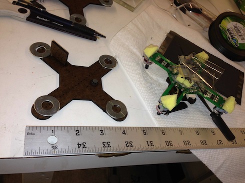
I also created a quick mock-quadrotor in Masonite for testing with the launcher. I figured it would help to have a separate apparatus for both the spine and the dry-adhesive landing gear. I hope Hao likes it!
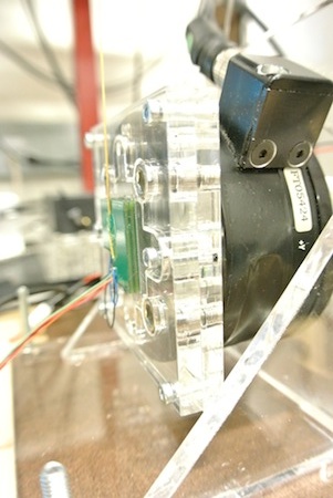
This week, I've also decided to work more closely with Alice on the shear and normal sensor project. Nikhil and Alice have been working fervently to fix and seal the several sensors for when Nikhil goes back to JPL. We found that the Plasti-dip seems to be a good option for sealing the sensors (the dipping kind, not the spray kind). It seems to bond only to itself, so it creates a shrink-wrapped seal. We did encounter a couple issues, namely that the plastic coating the wires has similar properties as the Plasti-dip, so it fuses with the seal. We also found it necessary to seal the dielectric so the liquid Plasti-dip does not intrude into that layer.
July 12
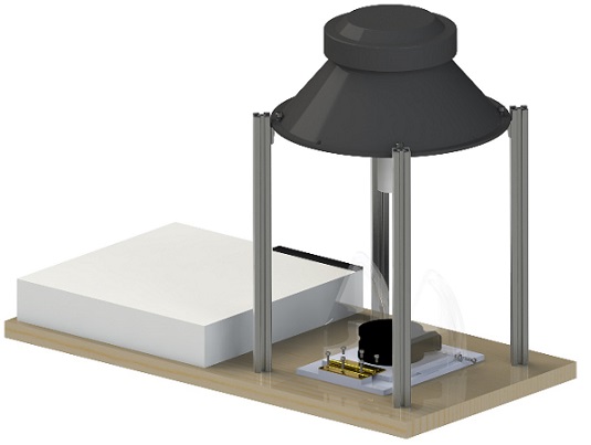
Wow, busy week. But productive! This week I've been working on an angled mount for the ATI force sensor. The intention is to be able to test and characterize the normal and shear channels on the sensors simultaneously. I CAD'ed up the design Tuesday, I'm proud to say, with minimal help from Alice (pics below). We lasercut the acrylic pieces yesterday, and the parts from McMaster should be arriving as I type. It'd be great to finish the setup by the end of the day.
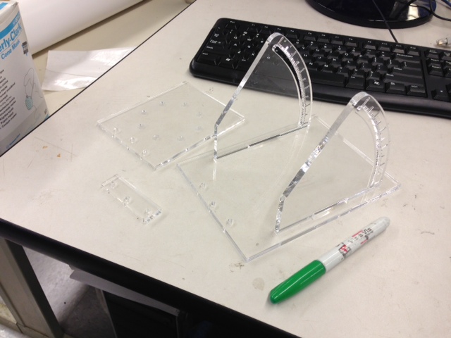
Some further notes for cutting Acrylic:
- Curf (or laser width) for 1/4" Acrylic (and in general) is about 10 thou. After measuring the material thickness of .233" a .220"-.225" slot made a nice press fit.
- Rastering (etching)- Any lines except Hairline-Outline will be printed as shapes instead of lines. Using a rastering setting on the lasercutter then allows you to etch the material. Rasters still show up faintly cutting through the masking. I ended up lowering the power/speed percentages from (90/6) to (20/6) as a pseudo raster to ensure the cut went through the masking. The cut unexpectedly went halfway through the material, which was more than sufficient. I suppose the laser cuts easiest at the surface where it's most focused, and perhaps the acrylic melts more easily than I anticipated. I noticed the raster settings were at 100 speed, so perhaps trying (50/50) or something similar would produce a better result.
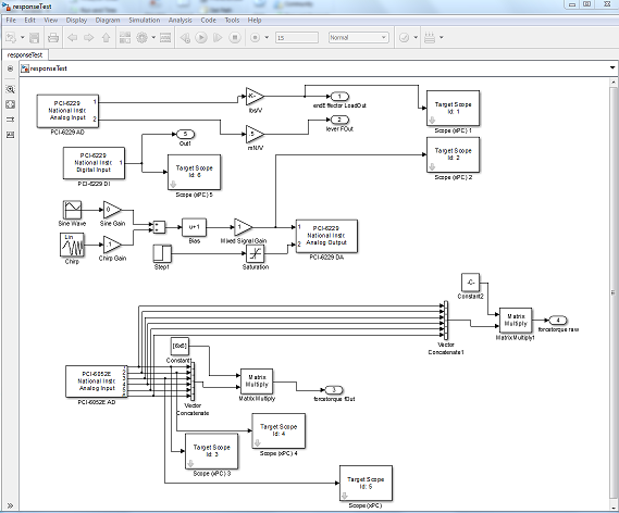
Yesterday we prepped the electronics for the test setup (the speaker and force sensor) and, despite how hacked everything looked, it ran quite smoothly! I got a taste of Simulink (the software running the sensors, which turns out to be a lot like Labview). I learned that a "chirp" means a test that sweeps multiple frequencies, from low to high. I also learned that the speaker can make annoying noises while testing. :S
We also did a couple of surface mounts! It was cool to see methods from my job last summer. I was a bit surprised that we are using paper labels as the stencil for the solder paste, but I guess it works! We're still trying to isolate the source of the noise Alice and Nikhil were encountering last week. The numbers are quite small--we're shooting for 5 counts RMS on a scale of 0 to 216--but the precision of the sensors matters! I wonder if trading a lower range of sensitivity for higher precision would be an attractive option.
On the JumpGliding front, Morgan is still trying to figure out an elegant way to use a single motor running continuously to repeatedly launch the glider. We're tossing around ideas with spooling coils, conveyor-belt/clothesline hooks, and one way casters. I was thinking it might be easier to use the carbon fiber rod used as the backbone of the glider as the element we wind against instead of attaching another string or wheel could be promising. Perhaps I'll get to prototyping a design in the coming weeks!
In any case, I'm looking forward to the first MERL barbecue this afternoon! Turns out we also have bagel club at the lab meeting, so we definitely won't go hungry today! Look forward to more updates and pictures of the sensor mount when it's done!
July 19
This week has been pretty slow. The sensor mount is done now. Turns out we needed a couple more small pieces (there are always those few things that slip your mind...). The xPC data system runs fine, and preliminary tests look promising. The resolution of the speaker as an actuator is so-so, but I imagine it will be sufficient for our needs. One possible concern that Dave brought up was the length of the effector arm. Because now we're loading the arm in shear as well as axially, we must be careful of the strength of the paper cone that's holding the speaker together. Perhaps making it shorter will reduce the annoying buzzing noise too!
Still waiting on the the sensor prototypes so we can begin the hard data taking (with luck we'll begin this afternoon). Alice has been focusing most of her efforts on finishing the paper with Natalie in preparation for the presentation today and their trip to Norway.
I've been playing with Solidworks a bit. Figured out how to use Lofts and Boundary Surfaces working with Richie to cut round shapes out of a block. Lofts are defined by two closed curves (start and end faces) and as many or as few 'guide curves' that connect them as needed. Boundary Surfaces (use for cuts and extrudes) are surfaces interpolated between several 'bounding curves.' The confusing 'direction 1 and 'direction 2' simply allow you to define curves at several points on the surface. Curves that are 'parallel' are the same 'direction', perpendicular are different 'directions' (see graphic below). In general, boundary surfaces will give smoother curves than lofts.
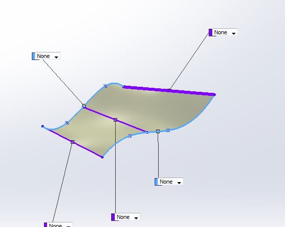
The directions are color coded. Here there are two curves in the blue direction, and three in the purple
We also spent an afternoon prototyping and hacking a coiling mechanism for the jump glider. After playing with the roller idea, (a continuously winding gear or roller that winds against a fixed surface like the carbon rod that releases by breaking contact), we decided both the challenges of manufacturing a small, light design, and one that could withstand the tension required would be better implemented with a winding spool. Morgan and Elliot came up with a very elegant design with a magnetic clutch.
July 22
Setting up the sensor! It's awesome to see everything in action. Couple key design lessons I've realized. Always keep in mind how the apparatus will be used, what constraints and considerations operation places on the design. The couple subtle features that would streamline the testing significantly are easy to see now--like making an end effector that can vary in height and position. The uniformity of the force exerted on the sensor could also be improved. We're currently using rubber bumpers, but at this point we have decided it's worth making a custom 3d printed/cast polyurethane part.
July 29
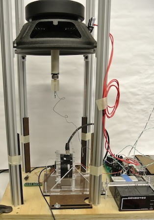
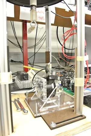
The test bed is now functional and producing usable data! We cut some masonite bars to ensure the speaker was flat and edited the bracket once again to accommodate the full range of angles. Complete with ball and socket joints and a variety of standoffs to adjust the length of the end effector for different angled tests, it's easy to use and ready to go! (on a side note, apparently I'm also developing my Billy Mays persona...). But in all seriousness, the ball and socket end effector does look pretty cool. I'm glad we figured out how to melt out the wax stuck in the joint (we used the heat gun, worked like a charm). Next we should probably cut the excess 80-20 and ensure everything will withstand repetitive use.
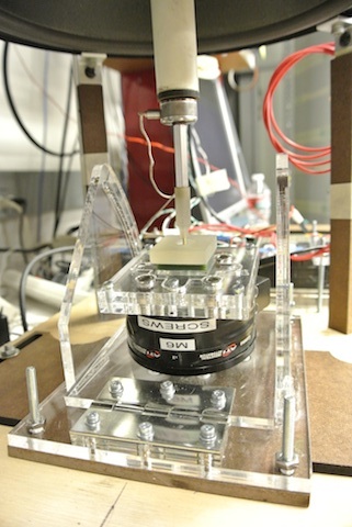
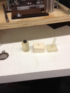
The evolution of the end effector
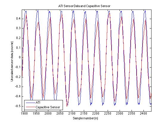
The data looks pretty good, as well. The moment on the end effector appears to damp the shear signal a bit, but it's readable and syncs up nicely with the ATI. Next we'll perform some dynamic response tests for these sensors, eventually in an attempt to develop an automated characterization script. Yay matlab!
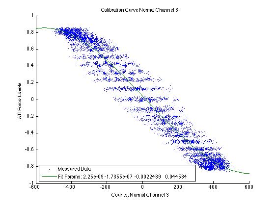
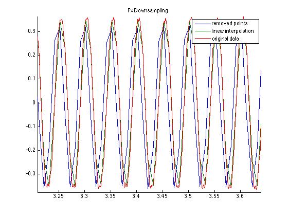
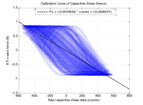
I've been doing a bit of analysis as well, altering and supplementing John Ulmen and Alice's existing code. Got the SVN Repo up and running (what a useful tool! in the future I may try to set up one of my own. So much better than conventional backups). I've been picking up a lot of cool tricks and such. Run_section allows you to run snippets delimited by the section dividers, and the exclamation point allows you to run bash commands from matlab! ("!echo $SHELL" prints /bin/bash in the console). The latter meshes nicely with the projects I've been doing on my own with javascript and shell scripting. Specifically, I've added fitting a 3rd order polynomial calibration curve to the normal sensors and downsampling of the ATI in an attempt to eliminate some of the FFT artifacts our analysis has produced from upsampling our sensor.
We're revisiting the issues with aligning the datasets in time. It might be worth trying to determine the gap in time between the time of the first sample and when the first sync signal is sent. We might also try reducing the sample speed of the XPC to match the sensor.
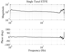
Eventually we'll try to generate what's called an ETFE, an experimental transfer function, of the sensor. This plot records how much the signal attenuates as the frequency of events increases, an indication of the dynamic response time of the sensor. In addition to a measure of the sensor's sensitivity and confirmation of the sensor's accuracy, we can confirm the utility and quality of our sensor!
I also helped Morgan with the release-clutch for the jumpglider launcher a bit. We determined empirically that the curf of the epilog laser is about .25mm or 10thou, and possibly slightly more if the material is soft. This measurement will help in designing nice press fits in the future. (The hole array I used is also on Yoda for future use.)
In addition, we're still troubleshooting a large difference in bias capacitance for one of the shear channels. Alice has confirmed the phenomenon in several boards, so we speculate it has something to do with the Eagle layout. Alice designed a test rig that will offset the boards slightly to see if we can manually fix the problem in manufacturing.
Today we'll be working on more analysis and creating and bonding the dielectric layers for the fabricating the sensors!
August 8
I'm frustrated that the blog does not save intermittent drafts. I will attempt to recreate the post I left half finished from the other morning.
Last week working with Alice we generated a bunch of good data. I had to make another laser cut apparatus to mount the sensors vertically (which took only a day to design and build!). I'm beginning to see the value of laser cutting as a rapid manufacturing method.
Taking data took surprisingly little time once everything was set up. Our next task will be to test the sensors with the calibrated muscle lever in an attempt to reduce the noise and resonant feedback from our current configuration.
Our data indicate the shear sensors work well at moderate force loads up to a dynamic range of about 50 Hz, half of our original goal.
We continue to have issues with the test setup, especially syncing the three different clocks we have. The xPC and the interrogator sync well with the pulse we set up, but between the AtoD board and the interrogator we have a currently unmeasured time offset. This error contributes to the phase shift evident in the calibration curves, and the numeric estimation that worked with the normal sensors has too much error for us to use with the shear sensors. Because we poll three to eight channels (one for each normal and two for each shear direction) the speed of the data transfer is significantly slower, 100-500 Hz instead of the 1.2kHz we achieve with a single channel.
In addition, the alignment of the capacitive fingers continues to impede fabrication of the sensors. If the fingers are skewed the signal becomes nonlinear, if they are offset, it reduces the range of the sensor and makes reading the signal difficult. For these reasons, we are looking into other options, including optical sensing, that might reduce the noise and allow us to make shear sensors with resolution and dynamic response comparable to current normal sensors.
This week I've been helping out with various small projects while Alice is away. I helped Natalie (after troubleshooting many technical failures) re-calibrate a load cell for use on the RDS project. First the xPC wouldn't receive the load cell data, so we ended up using a bathroom scale to get a rough estimate. After changing out our power supply several times in an attempt to limit noise, we finally took some good data using the Instron machine upstairs.
I did a little bit of laser cutting for Morgan's clutch. Morgan is working like a madman, but it's paying off with better and better iterations.
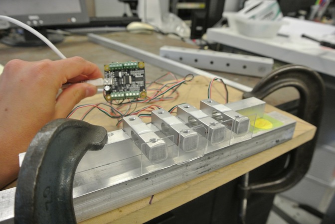
Mostly I've been designing and implementing code for a test setup for Elliot's gecko hand. We need to test each of the 24 tiles individually to ensure the differential is equalizing the forces as intended. So far, so good! Python is a fun language to write.
The data taken now has timestamps and is calibrated. Though I'm taking the data on my laptop, the error introduced by the threading should be negligible for the timescales we care about. Plots look pretty cool!
I did discover a very handy feature in matlab the other day also: anonymous functions. They allow you to write code blocks within script files (you store the function in a handle variable). Makes for less copypasta. :D
Anonymous functions in Matlab:
function = @(arguments) code;
function = parentFunction( @(arguments) expression with arguments, other arguments, ...);
q = integral(@(x) x.^2,0,1);
Last, but certainly not least, we hosted the MERL Barbecue today! Couple important lessons learned: People will eat whatever you put in front of them, and only faster if it's free. (i.e. It's better to put out less than half of what you have prepared initially. That way you have a shred of a hope that it might last for everyone. Also, people eat watermelon like fiends.) Even so, the event went relatively well. We seemed more prepared for the lunch rush than the others held thus far, and everybody loved the spices we put on the burgers. I always enjoy providing people a good meal. :D
Jon Renslo | jrenslo@stanford.edu