(redirected from Profiles.IsabelSummerBlog)
Isabel's Research Blog | Summer 2015
On this page... (hide)
- 1. WEEK TEN
- 2. WEEK NINE
- 3. WEEK EIGHT
- 4. WEEK SEVEN
- 5. WEEK SIX
- 6. WEEK FIVE
- 7. WEEK FOUR
- 8. WEEK THREE
- 9. WEEK TWO
- 10. WEEK ONE
1. WEEK TEN
1.1 August 27
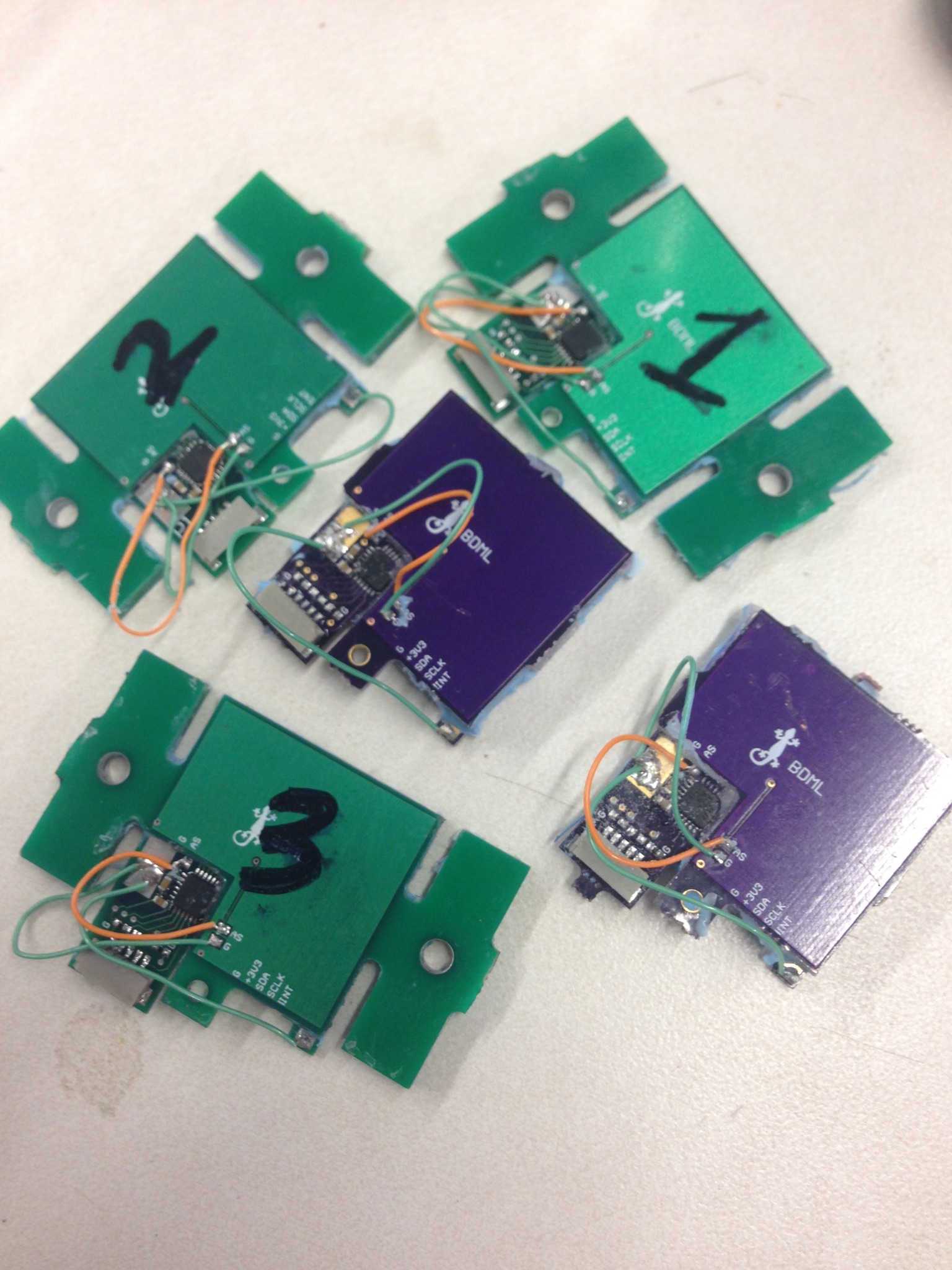
I spent the morning trying to get the shear plot to work. There had to be a better way than just multiplying the shear output I was graphing by some arbitrary number for each sensor. When I looked through the code, I found that if I saved the variable 'initial_sensor_data' into an array, instead of having it replaced for each data point taken, I could subtract it at the end from all the shear channels and that made my graph much more accurate! I also discovered that some sensors worked better when the data was multiplied by their calibration matrix, and some sensors actually worked better without that, just using the raw data. I tried re-running the calibration code for the ones that worked worse when using it, and discovered that sometimes the code outputs different matrices. So I repeated it multiple times until I found which matrix appeared most often and used that. It improved the data considerably, but I still think that for Sensor 7 I shouldn't use a calibration matrix.
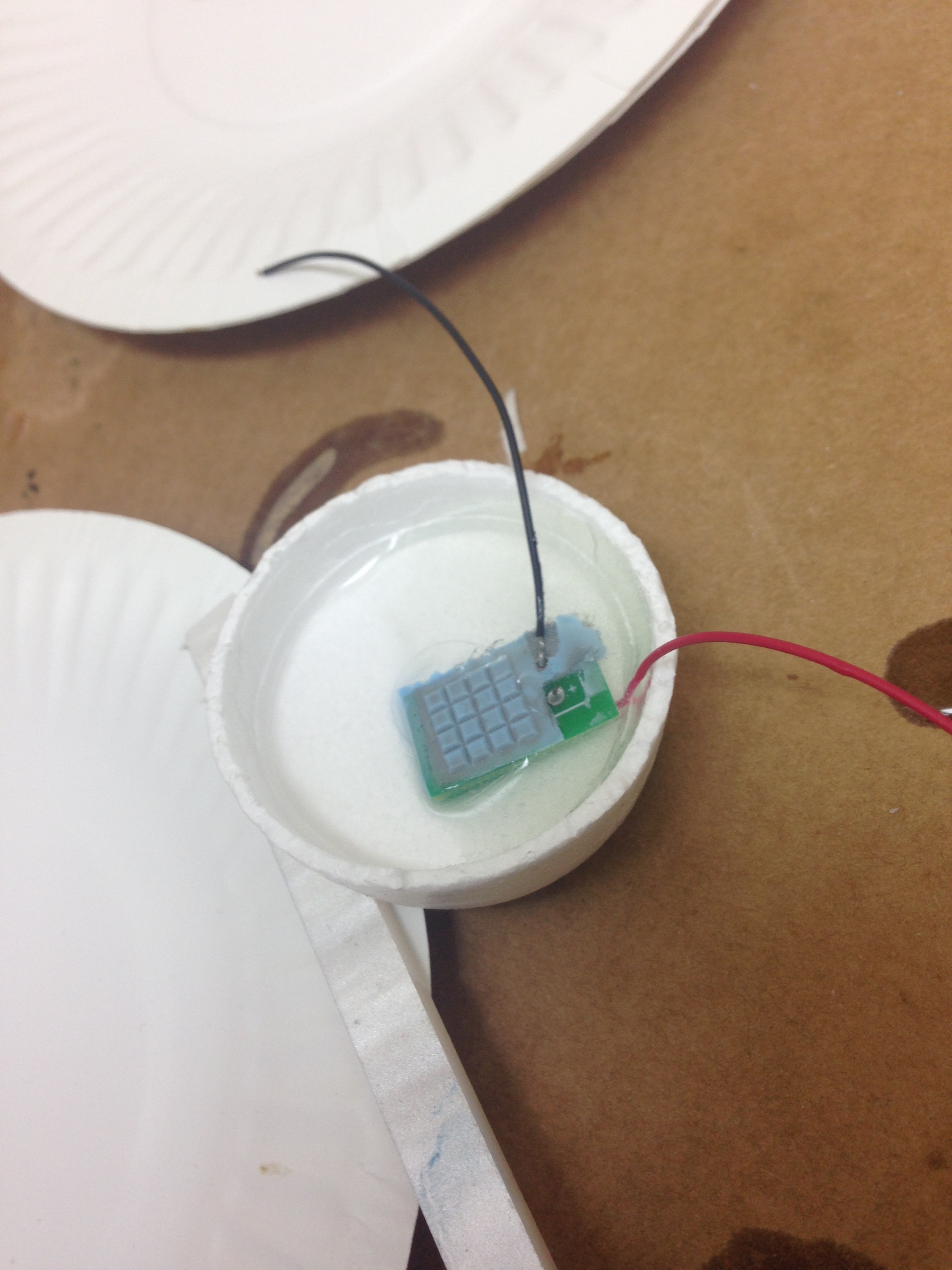
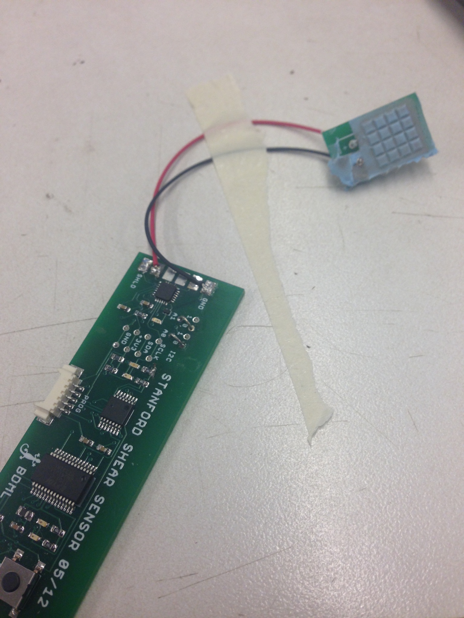
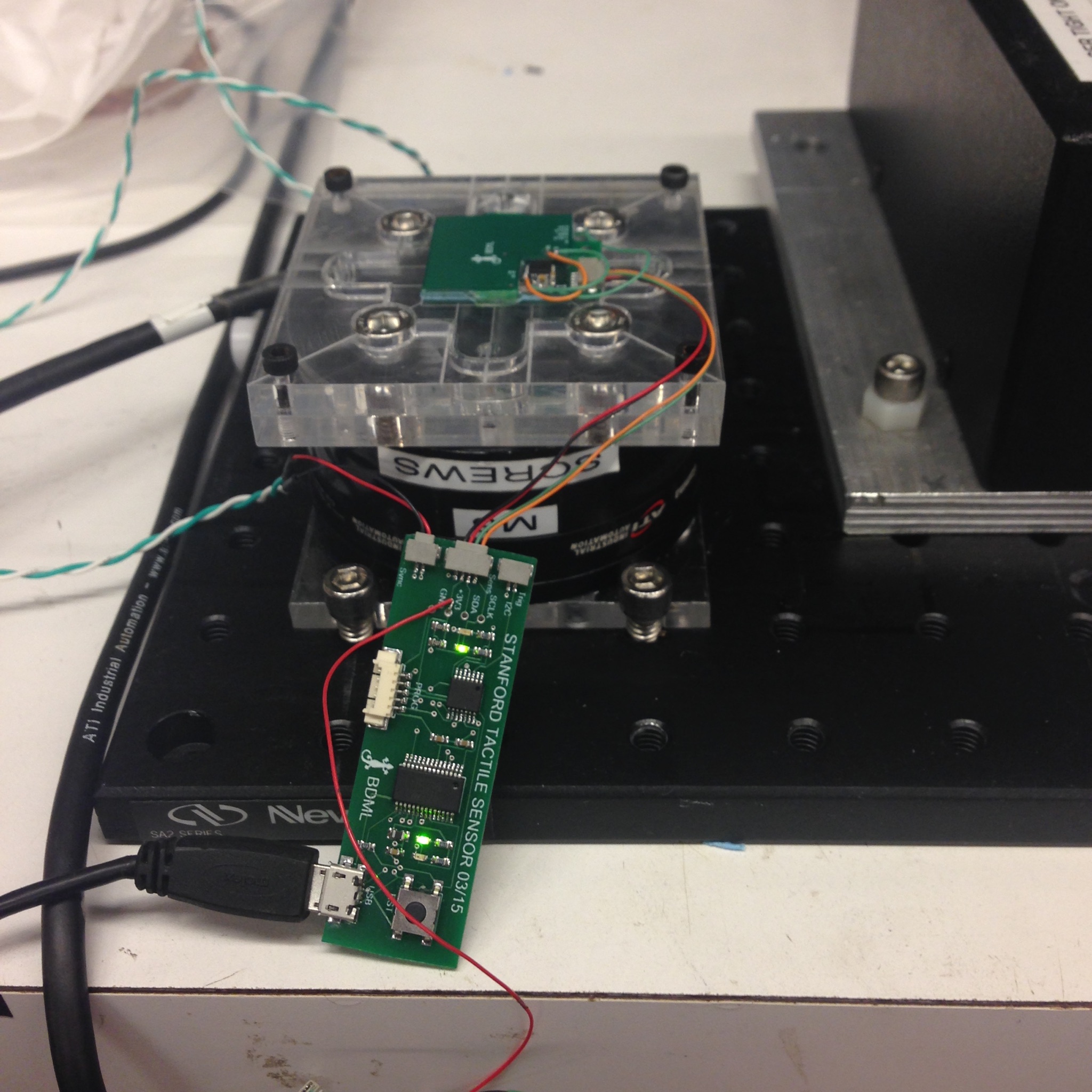
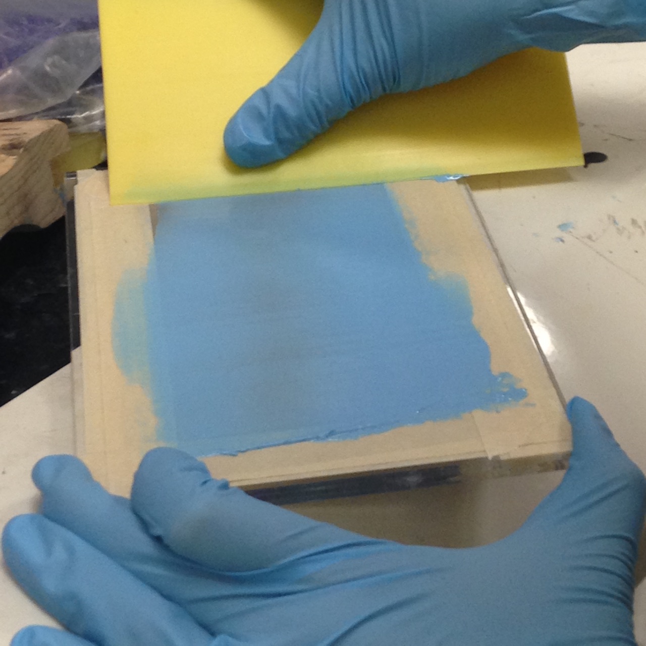
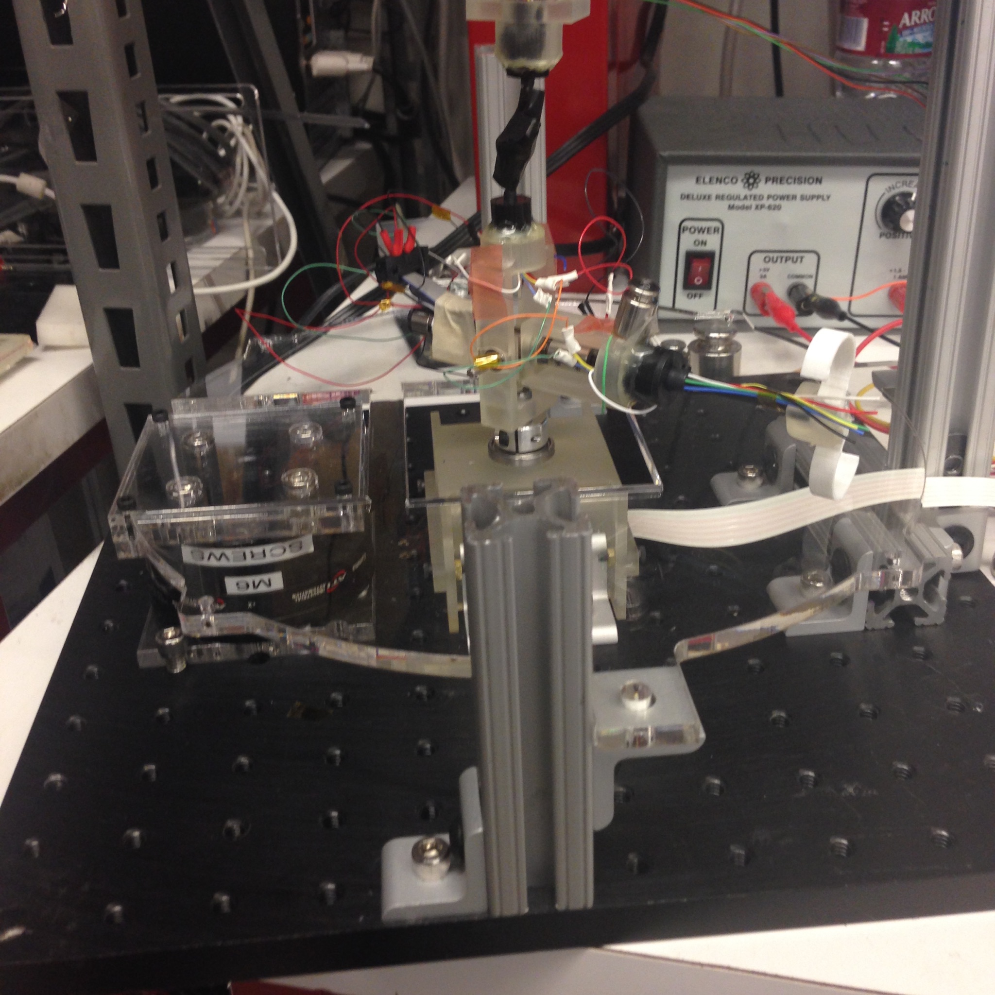
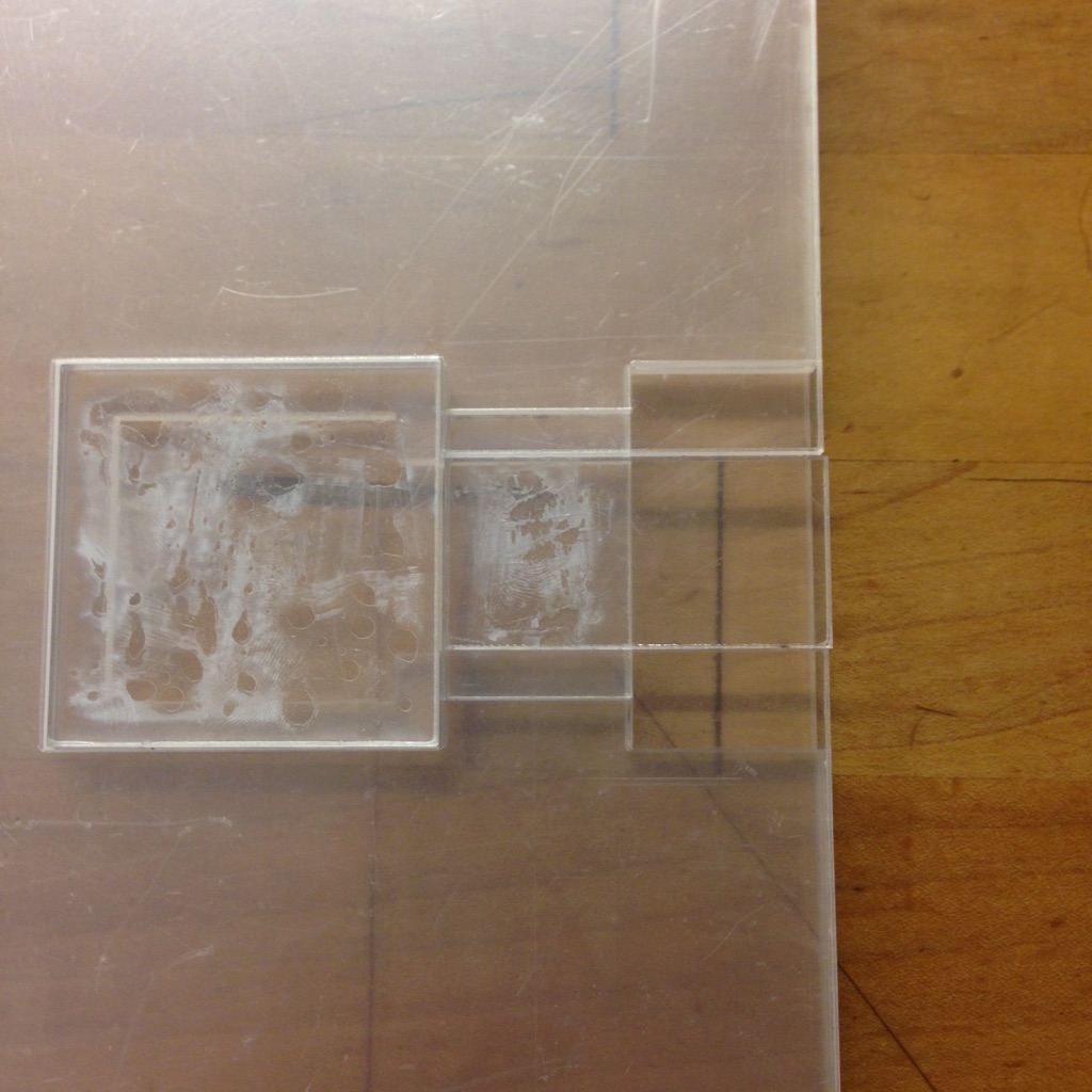
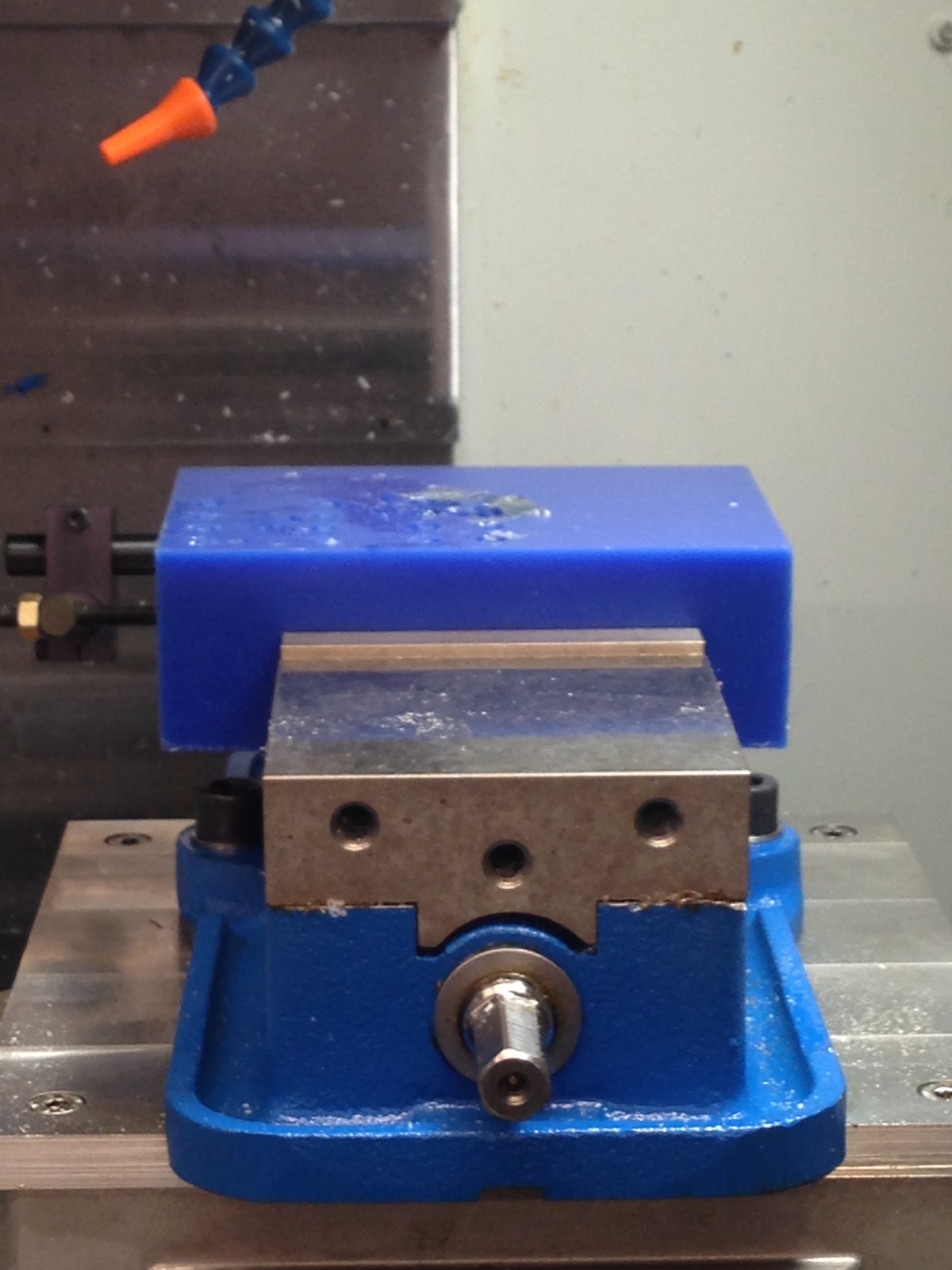
The setup I've been using to test the shear channels is below:
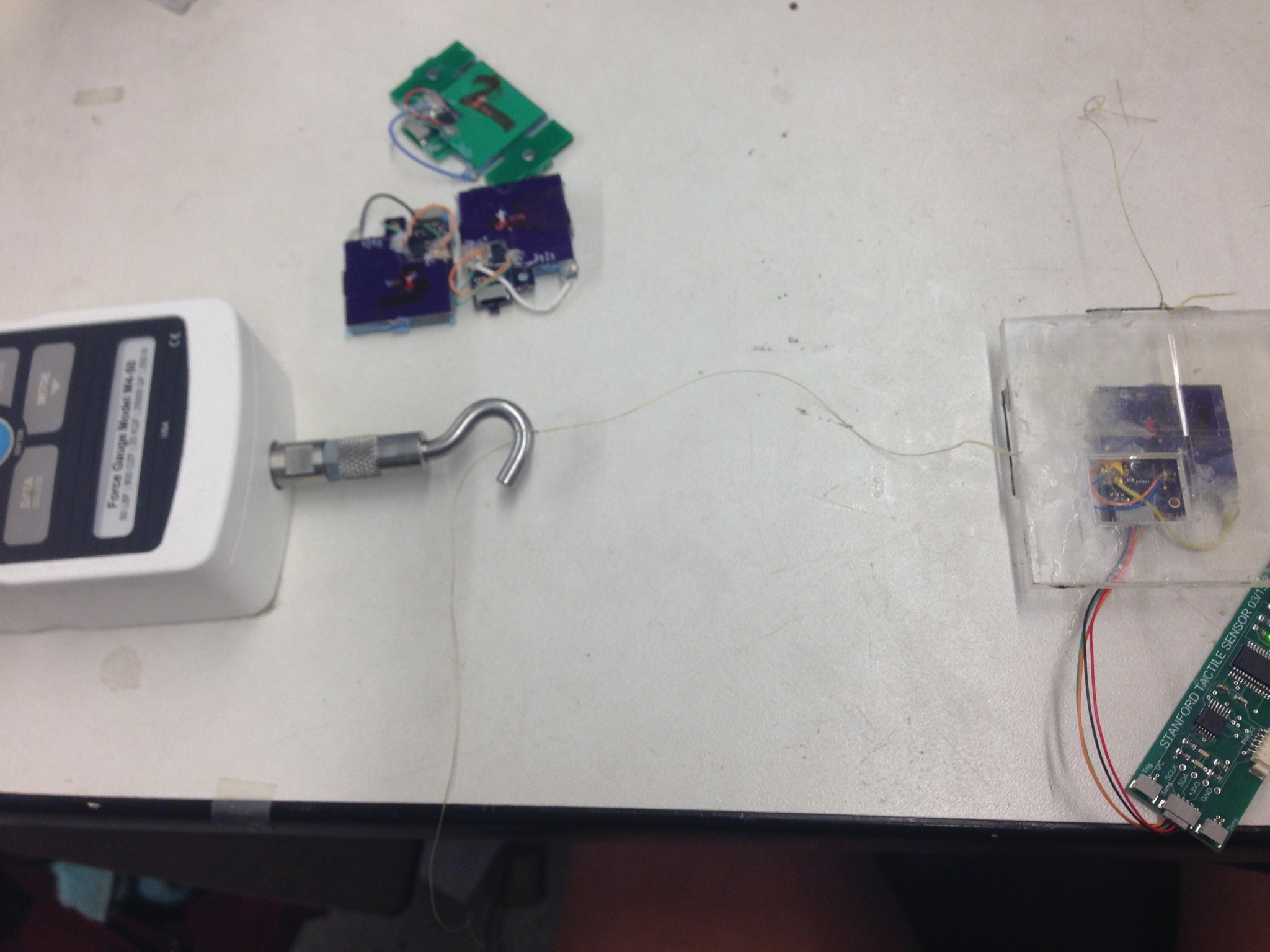
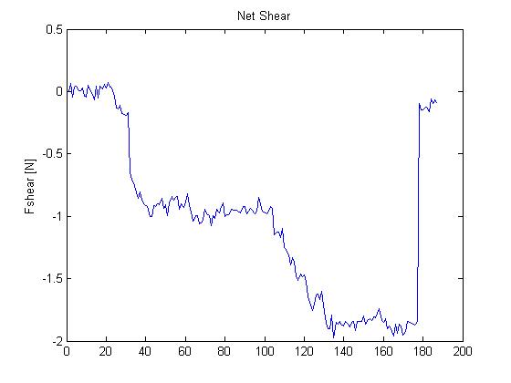
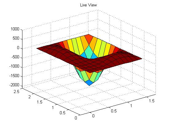
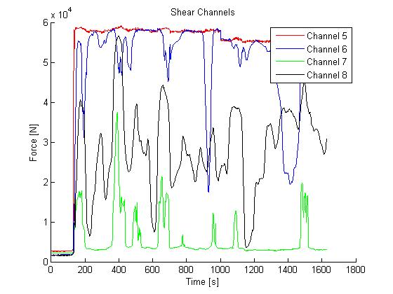
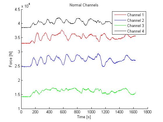
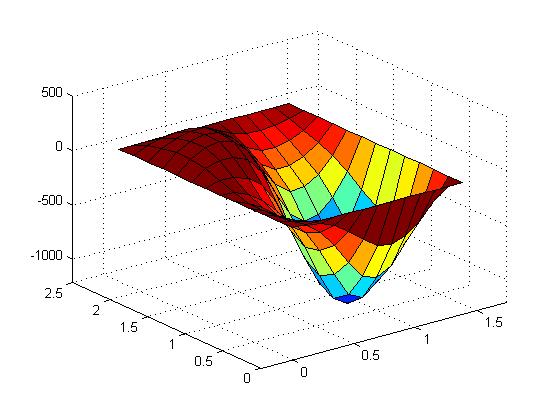
And here's a graph of the net shear plotted from one of the trials after I got everything working. The plate above the sensor was pulled with a load of 1 N, then 2:
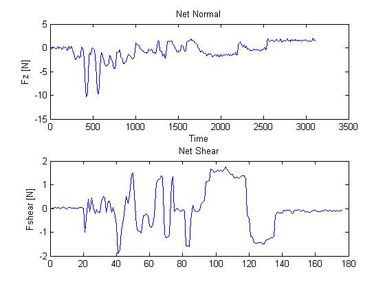
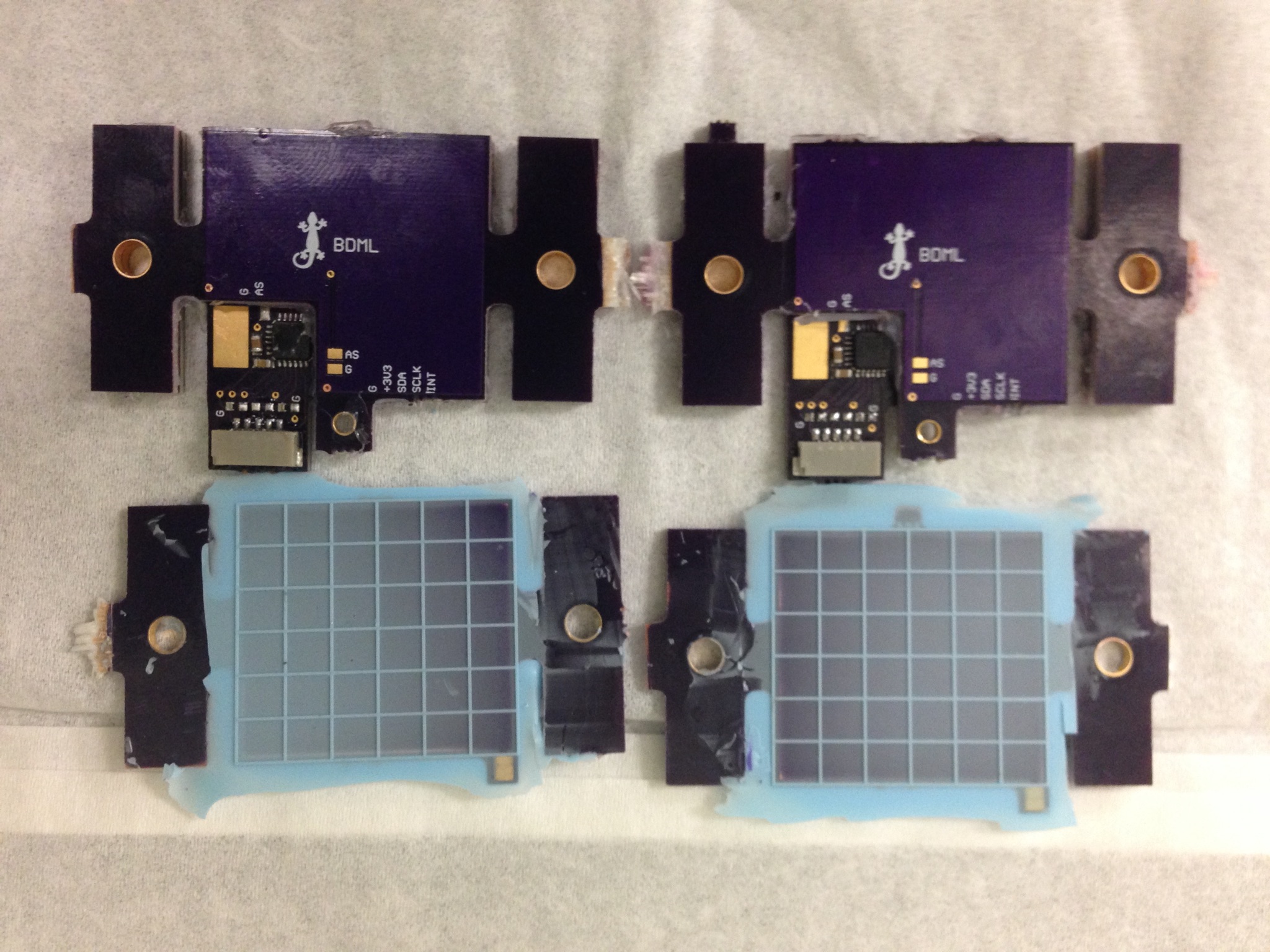
I also spent some time cleaning up a few things, mainly my work station in lab. I gave Hannah all the work on the underwater sensor so far. I cleaned up the code for the sensor as well and got it to the point where it produces a final graph that I'm happy with. The data points on the x-axis aren't the same numbers for the shear and normal for some reason, but each is aligned correctly so that they show the same point in time at the same location on the x-axis:
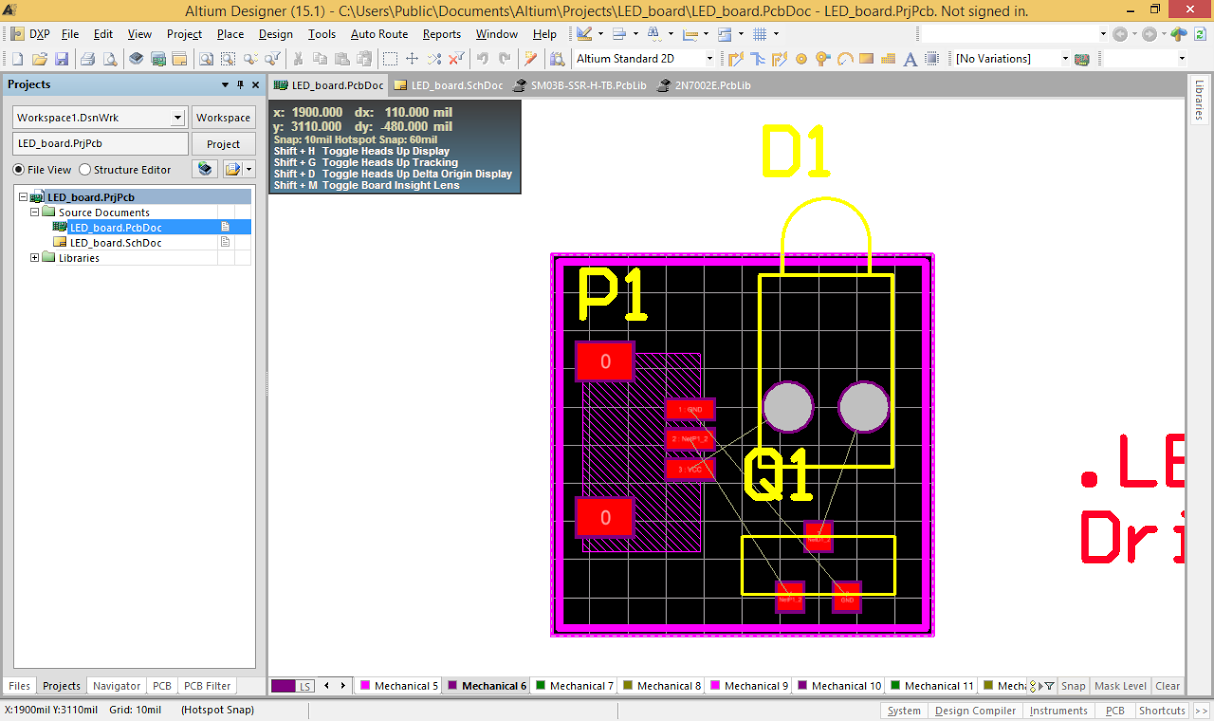
I talked to Alice about fixing the LED to ensure it doesn't change the capacitance of the sensor as well. She suggested a I attach a resistor between the LED and ground. I soldered one in between the GND pin and the NMOS and cut the trace that connected them, so now the LED no longer draws as much current. I checked and it doesn't affect the graph any longer.
1.2 August 26
I met with Andrew in the morning and Will in the afternoon to show them the board and hear their ideas for it. Both of them liked the board. Andrew wanted to see me get the shear working, as it wasn't quite there today, and Will suggested that if I have the time, I should find a way to get the matlab program to sync the data and the video footage of the trial. I think that would be a really cool idea mostly because I think students taking the class would like that part a lot. If I don't figure it out this week, I'm hoping I can work on it later after I get back.
Other than meeting with Andrew and Will, I spent the day calibrating the green sensor and trying to get the shear component to graph correctly. Each sensor is off by some multiple from the correct shear force, and that multiple remains pretty constant throughout the trials. However, there's a different multiple for each direction. I could go in and manually add these multiples to the calibration matrix for shear, but I talked with Alice near the end of the day and she said it wasn't worth it. Apparently, due to the shear force's hysteresis it won't ever accurately measure sudden forces, and will only accurately measure forces that are loaded slowly. This slow loading obviously won't work for the current application. I might still try manually adding numbers to the matrix, I don't know.
In the mid-afternoon, I picked up the poster I had gotten printed yesterday. Then I spent some time looking up ways to sync videos to matlab.
1.3 August 25
I finished the new green sensor and it worked, so I just have to calibrate it before the end of the week. Then I fixed up the second ME112 robot I have since I figured it would be useful to have two so I have some data to compare and look at trends. Everything is working really well, the only slight glitch is that the graph for each sensor will jump up a bit at 1000 ms into the trial and that becomes the new 0. For some sensors it's a small jump of .2N or so, for others it's a rather large one of 1N. It's something that can probably be adjusted in the code however.
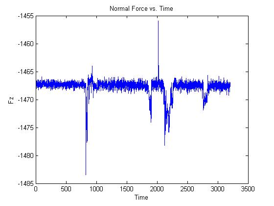
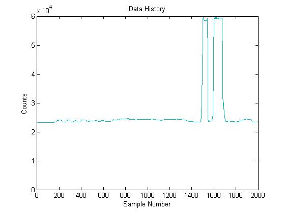
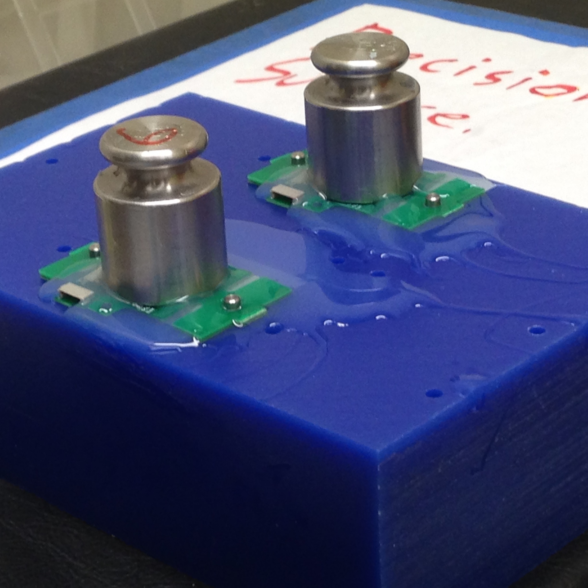
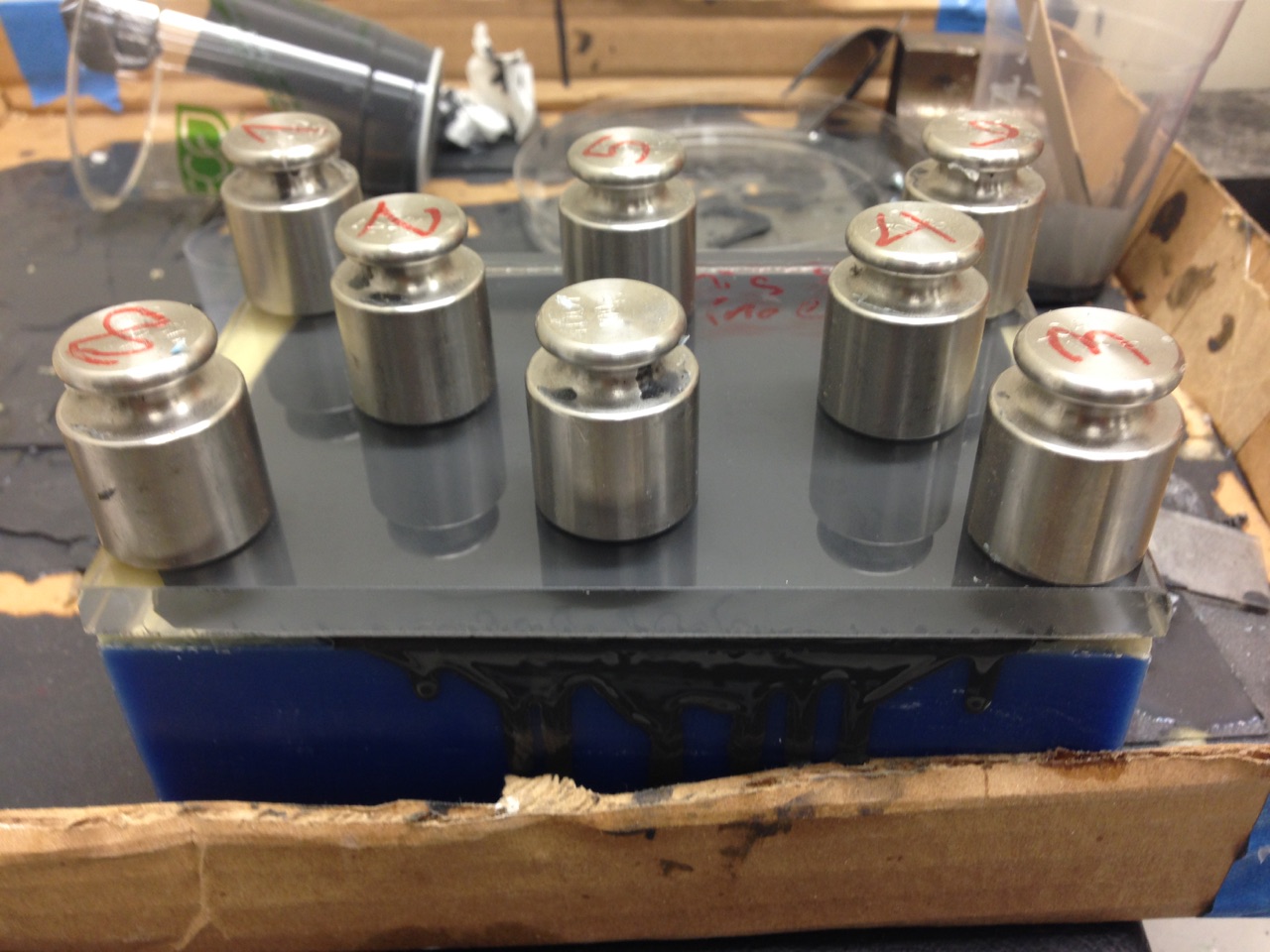
I talked to Mark and he thought it would be interesting to weigh the robots and divide that by the number of feet on the ground, then see what multiple of that number the sensor is reading as the normal force. For 112, we assumed the normal force to be around 2-3 times the weight of the robot divided by the feet. To check out what the sensor says, I weighed the robot and found it to be 542g. Divided by 3 that's 180.67. Before testing, I checked that the sensor was recording normal force correctly by placing 3 100g weights on top of each other and then taking them off. The data taken can be shown below:
The data clearly shows when weights are added and removed, and all the weights measured are accurate, so this is really good. I felt confident enough to test with the robot and recorded a force of a little over 3 N, or 305g. That's a little under 2 times 180. This is interesting because it's close to the multiples we chose in 112 but seems to indicate that this robot actually does better than that assumption. I'm happy with these results and will try to test the accuracy of other 5 sensors after lunch, as well as the accuracy of the shear component.
All the sensors except for Sensor 8 worked quite accurately (I finished calibrating sensor 7 and 8). I tried to figure out how to keep the sensors from jumping at 1000 ms, but I talked to Alice and she thinks the jump is due to the large LED turning off. So it's not a coding problem, and the only real way to fix it is to wait until the LED turns off before the letting the crawler walk across it, and setting the 0 to the average of the 100 data points just after the 1000 mark. It's mostly an aesthetic issue.
I also added in a section to the matlab file to plot the net shear component. Since the shear calibration matrix works a little differently than the normal matrix I'm not quite sure it's correct, but for now it will let me look at the shear data a little more easily. I glued on some bars to the plate that I can attach strings to and pull on it. I don't know where the equipment is to measure how much force I'm pulling with however.
1.4 August 24
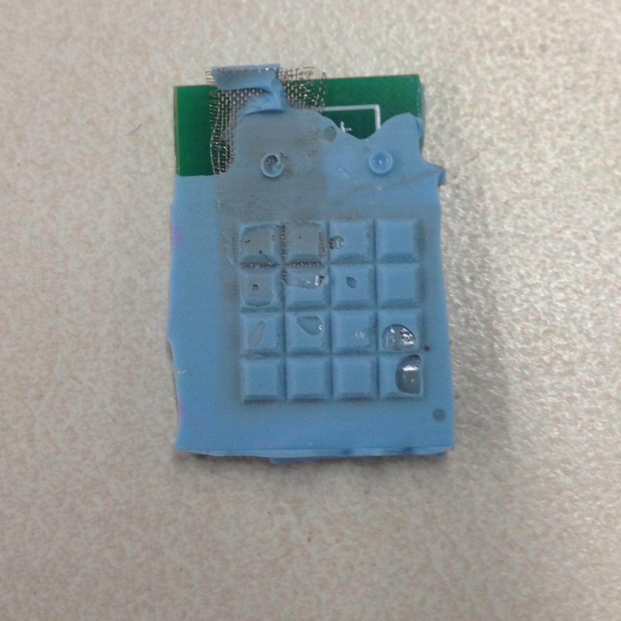
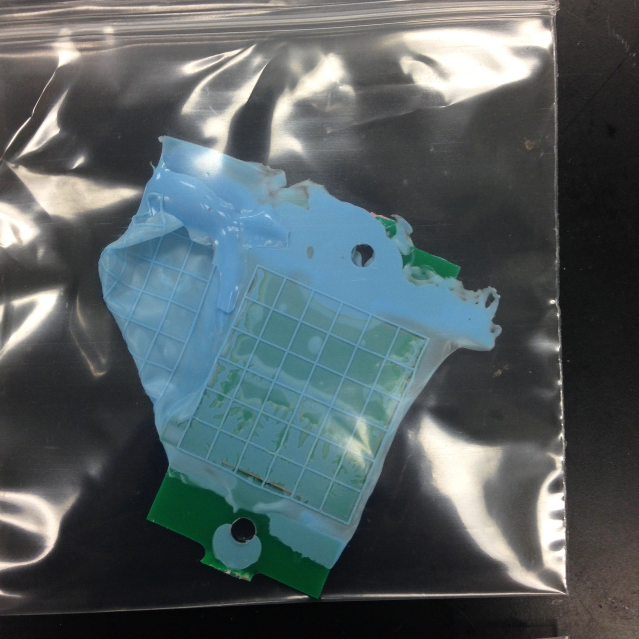
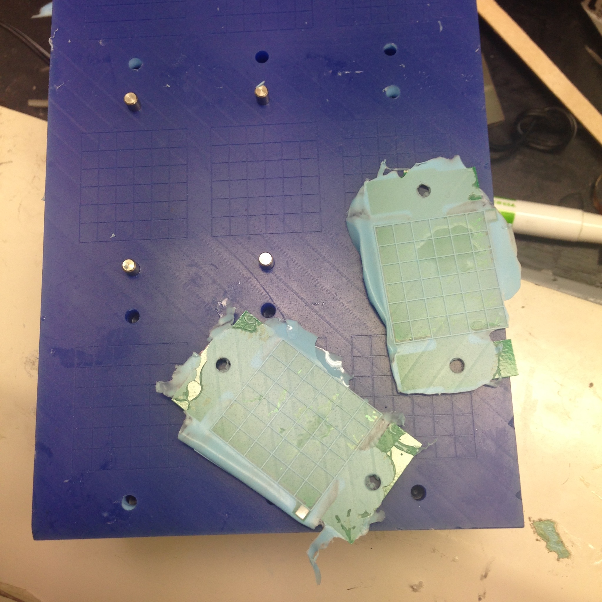
I checked on both casts from Friday and they both turned out really well. That meant I was finally able to test the underwater sensor in water! Only about half the grid was still functional after the cast, since epoxy covered the rest, but it still worked when I tested it dry and was able to pick up normal force almost as well as before. When I switched to testing it in water, it both worked and didn't work: It definitely picked up a normal force applied to the grid, and there were no problems with the waterproofing. The real problem lay in when the back side of the epoxy pressed up against anything. This would cause a huge spike in the signal that eclipsed any reading the grid picked up. Clearly epoxy doesn't work that well at shielding the back of the sensor, and something needs to be done about that.
I talked with Hannah and she's going to design a new pcb for the sensor that includes an active shield layer. It won't be finished by the end of the summer, but I'll be around all year and can come in to work on it whenever the new design arrives. The setup to make and test new sensors is all in place, so making new designs from here on out will be much easier.
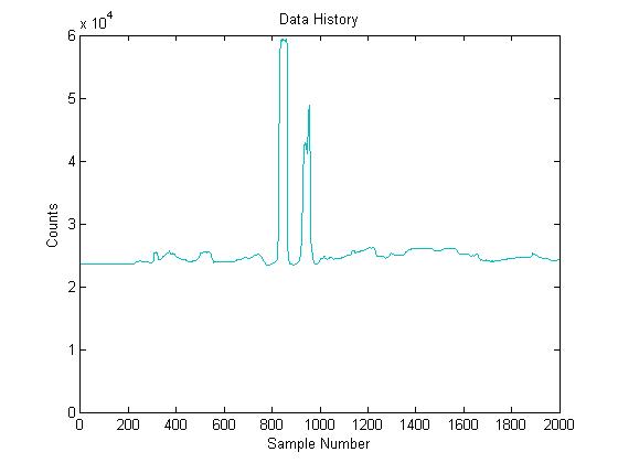
After working on the underwater sensor, I switched over to making my poster. I ran a couple more tests so that I could record the results on the poster:
I was really happy with the results because the crawler's foot landed on the pad well at least once for every trial, and the same robot showed repeatable results: ignoring some of the noise which makes the peaks look larger than they really are for certain trials, the sensor records around 7N each time. I think the results are very promising.
I finished the poster around 3 and then did the final cast for the green sensor, as well as laser cut a plate that is thinner and will work better above the purple sensor design.
2. WEEK NINE
2.1 August 21
I ran some more tests to try and characterize the sensors, but while I can measure almost up to 100N with them, I can only compare those measurements to actual measurements determined by a scale for up to 300 grams. The sensor "should" be accurate from the calibration, but I'm not exactly sure that it is. Alice has another more accurate calibration code that she might give me next week. I also ran calibration tests for the two new purple sensors, sensors 7 and 8.
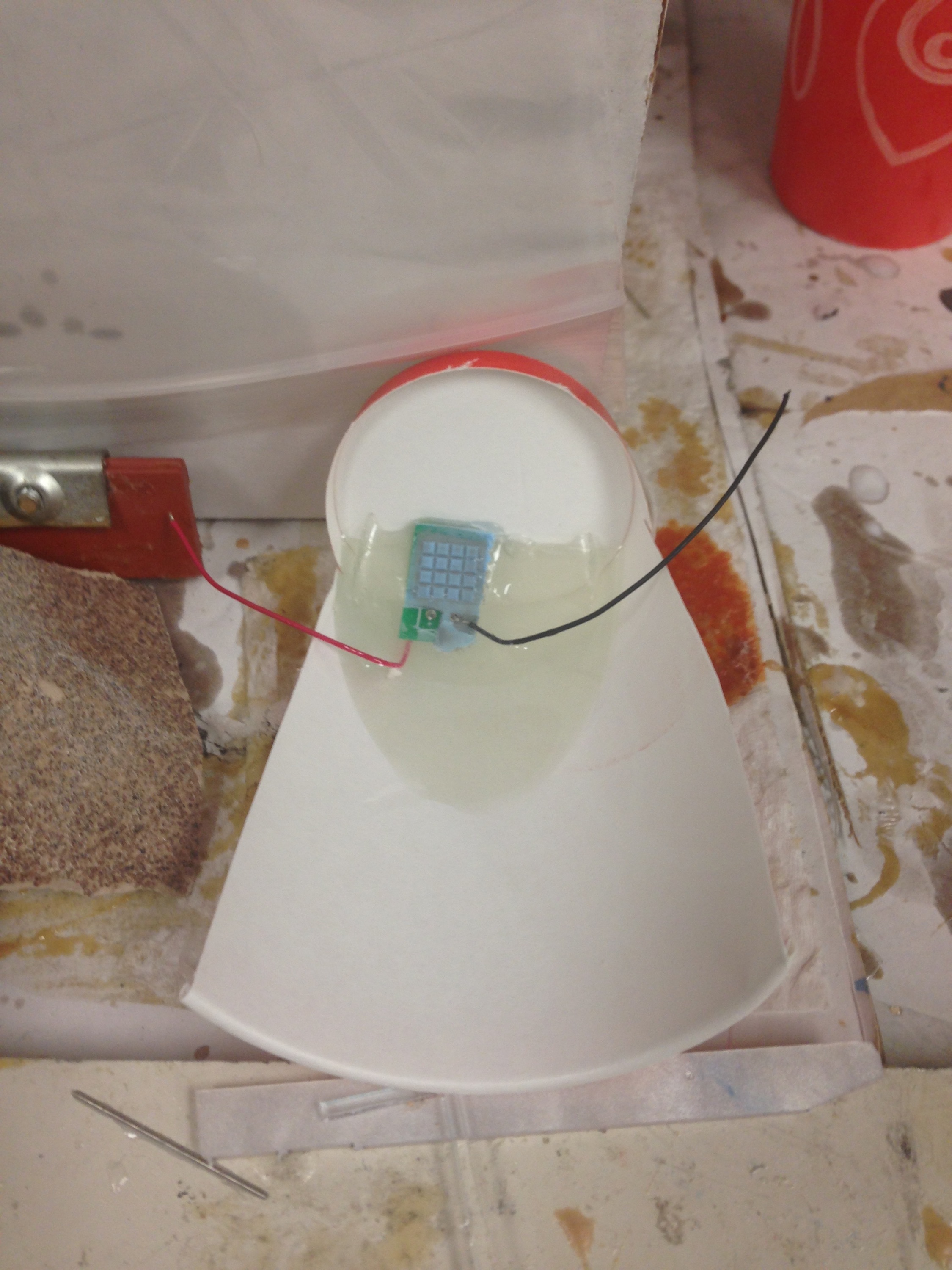
Lab meeting lasted until 11:30, then I primed another cast for the new green sensor. After lunch I cast that and did another cast for the underwater sensor since the vcc wire still was not fully covered even after the second attempt. This time I arranged the sensor and cup differently so that the bare wire would be fully submerged in epoxy this time:
Post cast this sensor prototype is going to be very cumbersome and ugly. But I wanted to be safe.
The boards I ordered that combine the AD7147 chip and the interrogator board finally arrived, so I was able to solder one together and will give that to Alice Monday to upload code onto it. I'm glad the order turned out correctly.
2.2 August 20
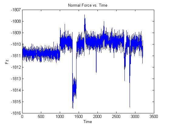
I decided to run some tests to try and determine the minimum weight the sensors could pick up. I ran the program a few times and placed different combinations of weights: I used metal screws of weights 1.6g, 4.4g, and 6.1g. The noise was too great for this weight however, since the noise had a range of 2 N and the weight was much less than that. The graph was also offset by around -2000 which threw me off at first. I fixed this by taking the mean of the first 100 data points. These data points are taken before any weight is added, and this is a method Alice has used before which is why I chose it. I talked to Tae and he also suggested I look at the standard deviation of these data points to get a better idea of what noise I'm getting.
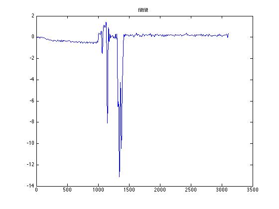
I looked up several methods for filtering noise, and decided the best idea in this case would be to try a filtering method that filters the data after it's taken. I made my own filter that averaged every 5 data points and plotted that. The effect can be seen below:
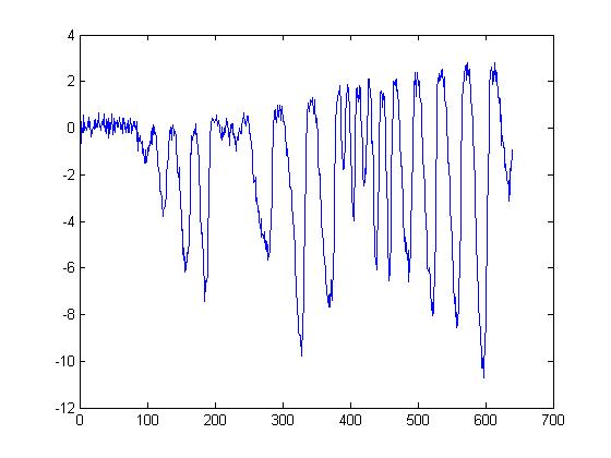
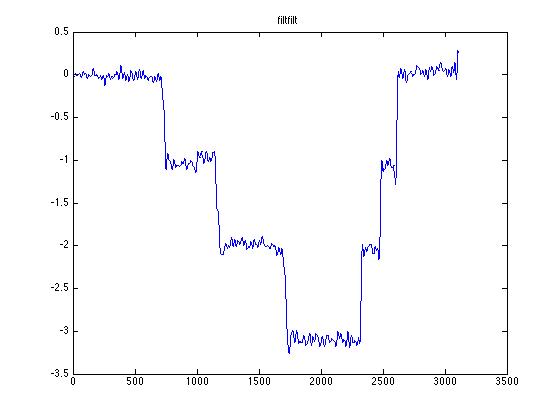
The other option is to use the matlab command filtfilt and filter out all frequencies above a cut off frequency, however I wasn't able to make that work just yet.
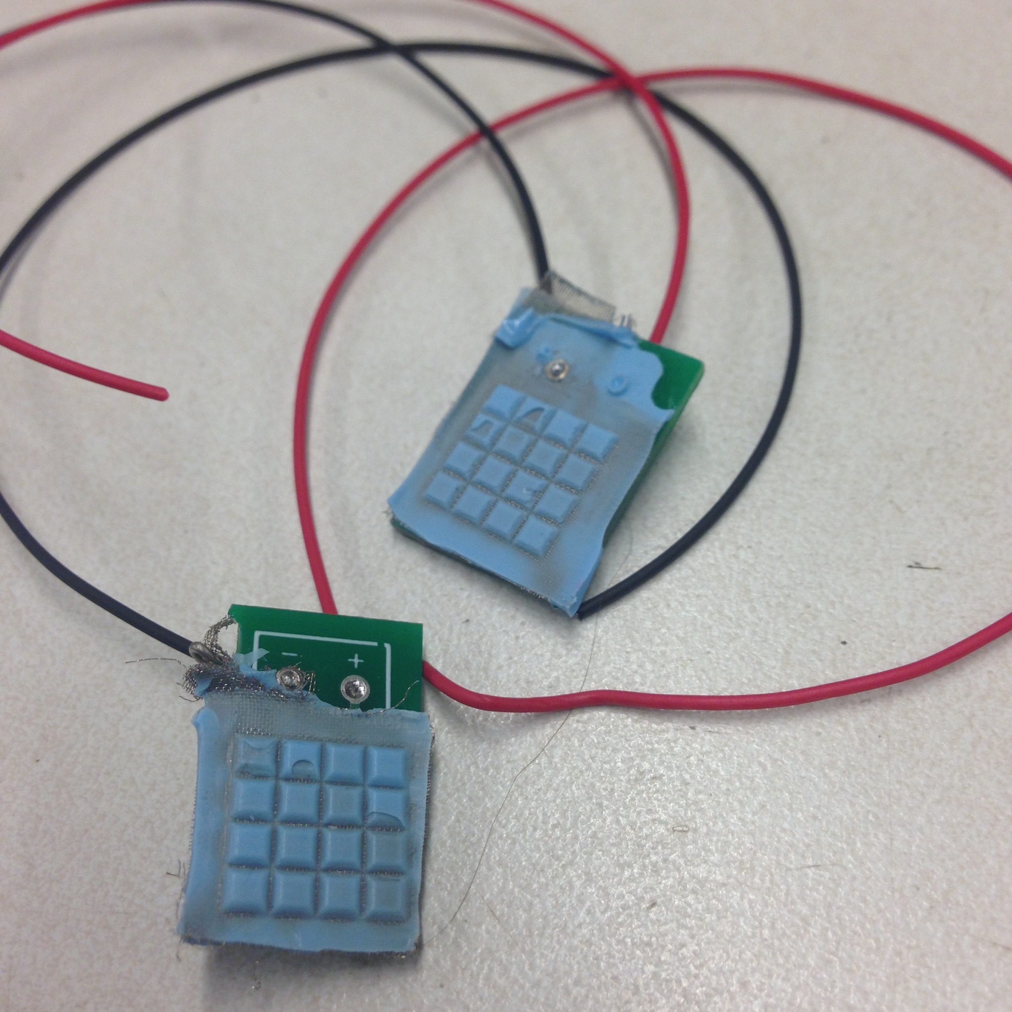
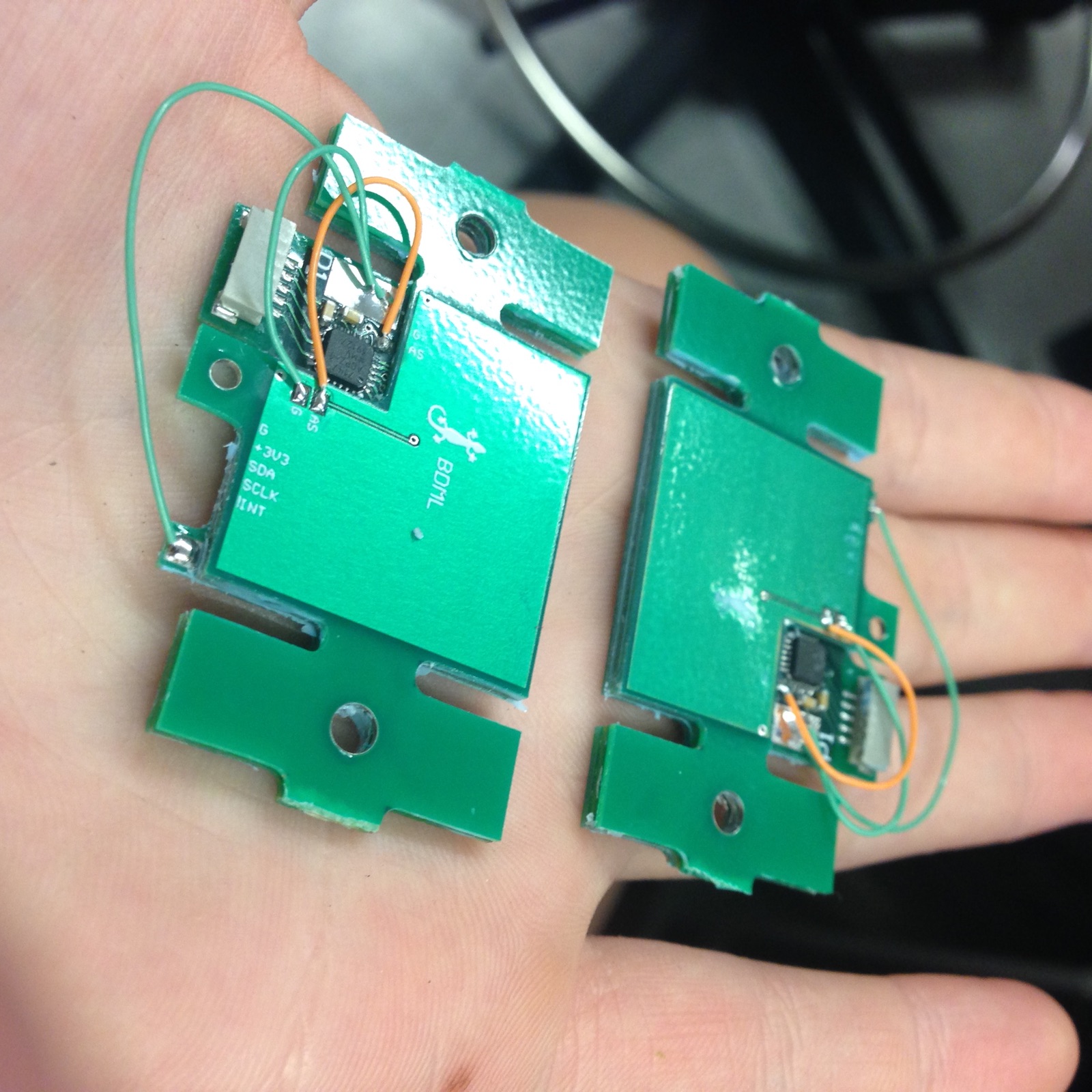
While I played around with this, I used the data from each trial to create an excel doc with the standard deviations I was getting for each sensor, as well as the maximum and minimum forces recorded so far with it. I also changed the wiring for the sensors to different colors to make each sensor more distinct from one another, as the sharpie method rubs off after a while, and I hotmelt glued the wires to add robustness. They look like this now:
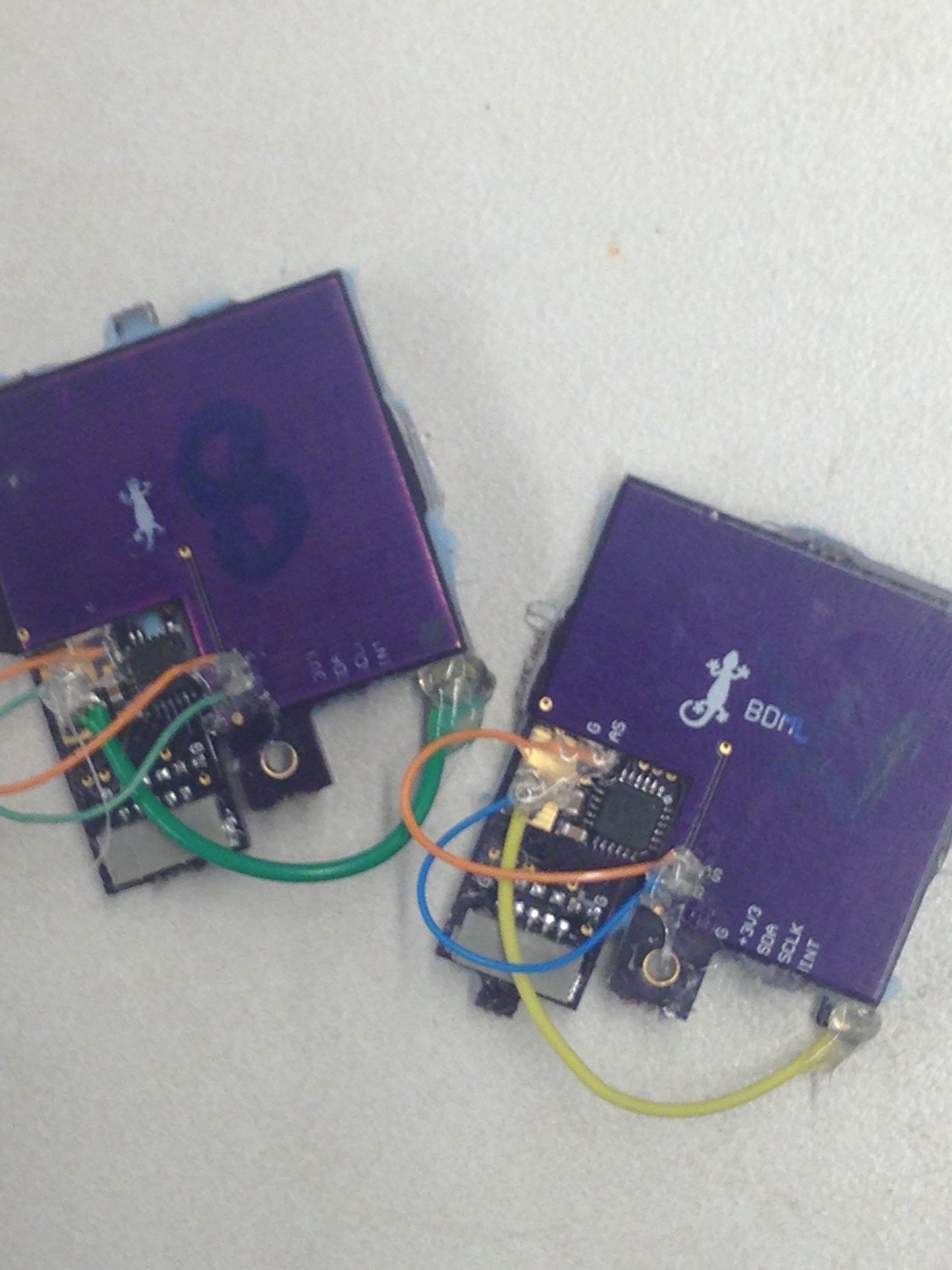
After doing all that, I headed over to the TLTL to cast another normal layer for a new green sensor and to check on the underwater sensor cast. It looked as though a part of one wire was still sticking up out of the epoxy, so I decided to cast some more epoxy on top of that before any testing.
3pm: Finally got filtfilt to work!
2.3 August 19
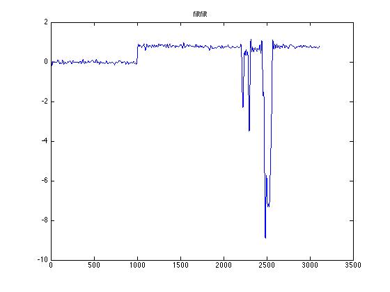
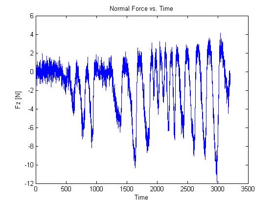
I edited the matlab file to show the net normal force. I decided to plot the graph from start to 50 data points before the end of the trial, since the normal force would shoot up to 0 as the sensor shut off: If that were to be included, the graph would end up very zoomed out and hard to read. Below are graphs from three separate green sensor trials:
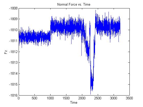
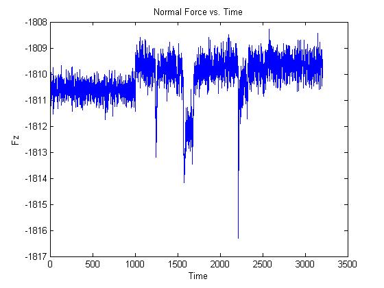
This sensor has a lot of noise, which a band pass filter might fix, but overall the results were really great! The sensor was very robust and didn't freak out a single time, and I was able to get the robot to walk across the pad every trial. That had been a huge difficulty with the smaller 2 inch pad. It seems like 2.5 inches is a much better option.
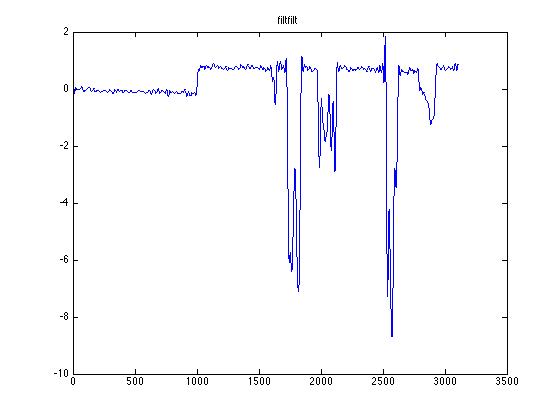
Below are the graphs from the purple sensor trials:
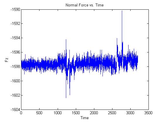
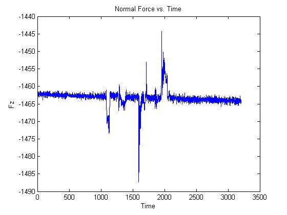
The first graph shows data taken by Sensor 4. For some reason this sensor had a lot of trouble today and broke down several times. However, I switched over to Sensor 5 for the later trials and those are represented by the next two graphs. There's A LOT less noise for this sensor and as far as I could tell it was as robust as the green sensor, Sensor 2. I don't know what part of the casting might account for the difference in noise level of each sensor, I just find it very interesting that there's such a marked difference.
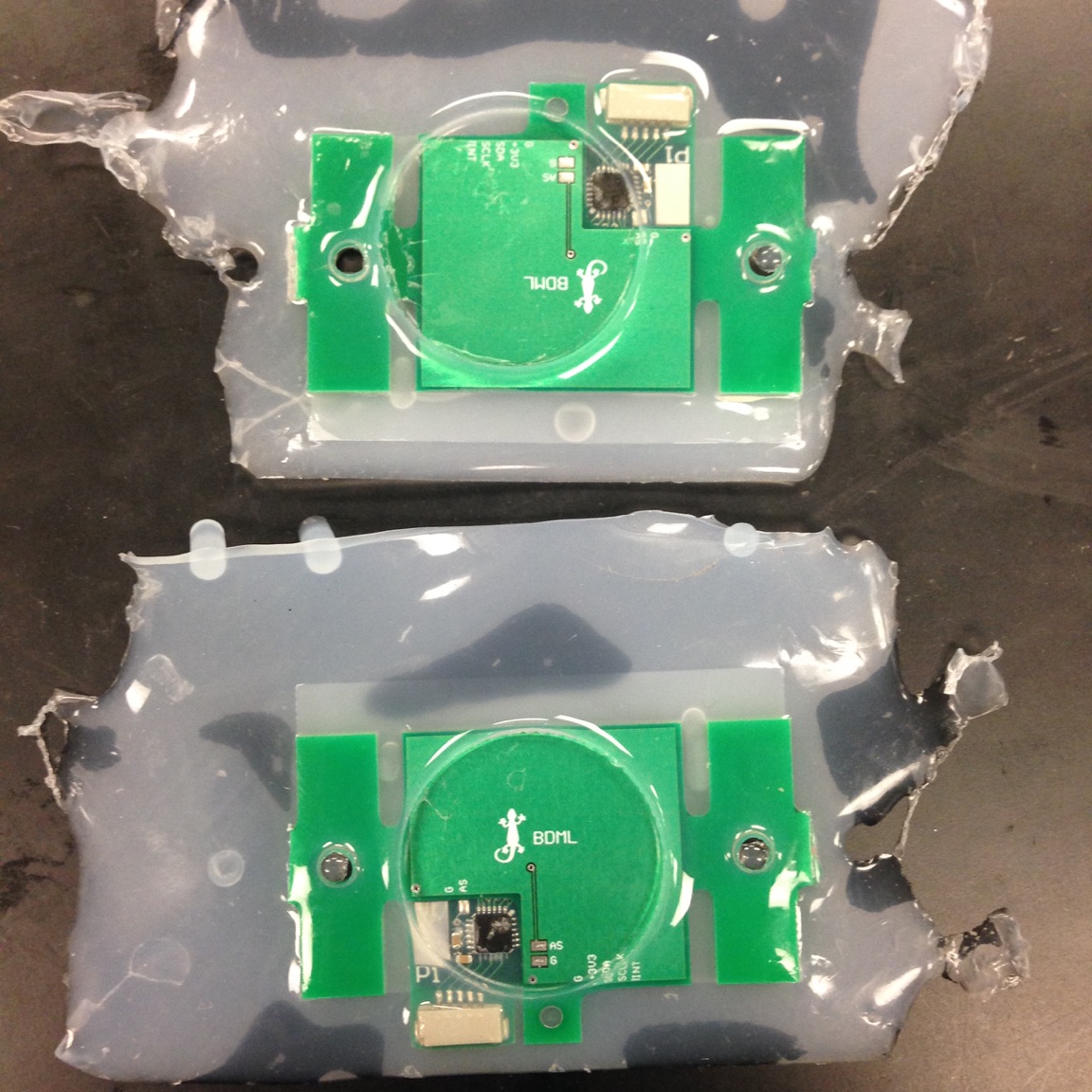
I also finished the final cast for two more purple sensors today, and cast the underwater sensor in epoxy with Hannah - she thinks this is the best way to waterproof it. A few of the grid blocks got epoxy on them which means they'll probably be too stiff to register force well, but most of the sensor should still be useable. So that will be done tomorrow. The epoxy cast setup turned out like this:
At 3 I met with Hao and Alice to discuss characterizing the sensors. I hadn't understood that what we were actually meant to characterize was a limit curve for the adhesive Arul is going to cast on the bottom of the two sensors I gave him. But Alice walked us through the process she wanted so we should be ready whenever we get the sensors back.
2.4 August 18
I was able to calibrate the purple sensors. Alice explained that the problem was she has multiple matlab scripts with the same name and I picked the wrong one, so after using the right now everything was fine.
I spent some time again trying to figure out why the calibration scripts that call on the calibration data still won't run on the computers I use. I got a little closer by using the ver command to determine which computers had what matlab extensions: I was able to find a computer in lab that has the XPC targeting extension, and by running on that computer I eliminated the orange error I've been receiving on all the other computers. However, the linspace error persisted even there.
Alice came in around 11 and made a few changes to the calibration code which brought us closer to figuring the problem out, and then finally right before lunch I was able to get it to work!! Which means I'll get to test out the 112 board setup again in the afternoon, and can compare how the purple sensors do with that as opposed to the green sensors. I also talked with Hao and we agreed to characterize the sensors tomorrow. Below is one of the figures generated by running the fixed code. It shows the ATI data (the standard lab sensor we test our version against) versus our sensor data for shear in the y direction. blue is the ATI, green is ours.
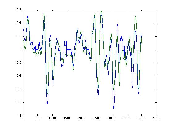
The fit for this graph turned quite well, although the fit for others was not quite as nice. Still they all seemed to be working: Both the purple and green sensors work with the setup and do pick up a reading from the 112 robots. Alice suggested I adjust the code so that the net force in the z direction is plotted; she thinks that will make a more readable graph and allow better comparisons between the sensor designs.
2.5 August 17
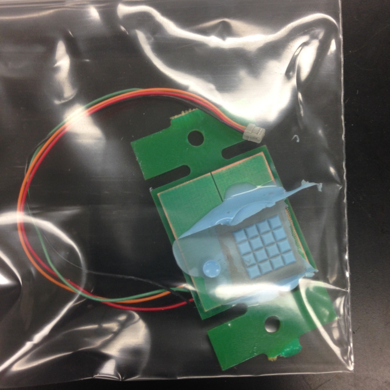
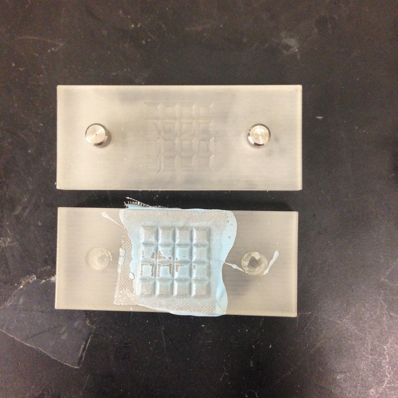
I fixed the connectivity issue for the underwater sensor by switching the wire over to the front side and alligator clipping it to the mesh:
Matlab still shows the same error message however which means it's probably also a code problem. To double check, I decided to re-solder Alice's old sensor back onto the interrogator board to see if this code worked with that one. If it did, the code either had issues with the new design and needed to be altered, or worst case scenario the new design simply didn't work. It turned out that the code didn't work with Alice's old design either.
I was able to isolate the error because it only related to plotting normal forces, not shear. I got the shear version of the code to run, which was encouraging. Still, the underwater sensor is meant to sense normal force so it was really that version that I needed. By comparing this code to the current version I use for the regular sensor design, I was able to locate several points in the code under the normal section that assumed 8 sensors instead of 4. I changed them so that they only called on 4 channels, and got the normal version to run. I'm not sure I called on the 4 channels in the right order, but at least the graph finally appeared and was able to read data!
These are the graphs from the first time testing the updated code on the underwater sensor:
I ran some more tests, and the only thing that worries me right now is that the back of the sensor is much more sensitive to touch than the front with the grid on it. I think the design needs to include some kind of shielding to protect the back. For now, I taped the back to acrylic, then taped that to the table. Not very scientific, but it seems to be helping somewhat, at least because it keeps fingers away from the back. I also noticed that certain of the grid blocks were much more sensitive when pressed individually. This is the same result we got with the initial prototype, however from this model it's clear that the more sensitive ones are the blocks that turned out slightly taller, with a little more silicone on the top.
When Hannah comes in next we should probably talk about how we can change the design to deal with the connectivity issue of the rivet design and the ultra-sensitive back, but overall I feel that this was pretty successful.
I spent the rest of the day casting more purple sensors.
2.6 August 16
I came in on the weekend because I had wanted to help Alice and Tae run some experiments, but those went faster than they expected so I ended up working on my own stuff.
I was able to make some headway in both the underwater sensor project and the ME112 board project: For the underwater sensor, I asked Alice if I could borrow the interrogator board that acted as a breakout for the PIC. I don't know when the one I ordered will arrive, and I figured I could just un-solder Alice's sensor from the one she already has and then solder it back on when I was done. She suggested I run the matlab file Tactile6x2 that she had sent me at some point, and change it from 8 sensors to 4 sensors. I soldered the GND from the sensor to the GND on the board, then the VCC to one of the 4 connections to the PIC. Unlike Alice's sensor, there was no shield wires to solder on. I tried running the code and there were some errors, but still I'm farther than I was. I think in this case there might be some errors with the sensor design and not the code, since I'm not sure the rivets are really connecting well to the conductive mesh. I'll talk to Hannah Monday.
For the ME112 sensors, Alice and I were able to figure out that the issue with the interrogator board came from the jumper cables being incorrectly wired and not from the board itself. That meant I was able to correct the jumper cable problem and finally test the new purple sensors. I ran some preliminary tests to see what the difference in force measurement would be between the purple and green designs. As Alice had predicted, the purple boards seem to measure a slightly lower magnitude for normal forces, but for some reason the shear force was unexpectedly better than the green design. I was surprised about that, but it's probably just a casting thing and not a design thing.
I still haven't been able to properly upload the calibrated code to the sensors from a computer other than Alice's. Monday I'll try another computer in the lab besides this one, but I think there might be a file the code needs that's only on Alice's computer. The COM ports also stopped working correctly on the computer needed to calibrate the sensors. That means I'll wait to calibrate the purple ones til Monday too when I can ask someone else in lab how to resolve COM port issues.
3. WEEK EIGHT
3.1 August 14
I came in early so that I could use the ATI. Things were going well until the interrogator board started freaking out. Alice is going to try re-uploading the code for it while I help with the bbq, if that doesn't work there's an extra board.
I ran calibration tests on all three sensors again and finished up the purple sensors by cleaning them up after the last cast. I took a picture of all the sensors together:
The interrogator board was still iffy all day, so I spent a long time trying to get that to work. If I can't debug it by Monday morning I'll just make another one, since Alice will need the extra one eventually and it can't stay with this project.
3.2 August 13
The casts from yesterday turned out the best so far, the normal layers were close to perfect. These sensors will have taken around 2 days to make total, down from the week it took to make the last couple. It's too bad I finally got so fast at the process when I don't really need to make any more sensors...
The purple design post cast looks like this:
I primed it for the final cast and also finished the underwater sensor by inserting the rivet and soldering wires on. It would be really nice if the interrogator board for those sensors arrived next week so that I can test them during the summer. It was probably a mistake to order ground shipping. If worst comes to worst I can just test them when I return in September.
When I tried to run the calibrated code from yesterday, the linspace error appeared again. The version of the code Alice sent me has never actually worked, and instead she's been doing it on her computer, so I feel like I might be using an older version. Yesterday Alice had mentioned she wanted to improve the code, so I'm hoping when she gets to that and sends me an updated version it will also fix this problem. Until then, I've been going line by line through the beginning again in order to try and find where the problem is. I think it might be a problem in the lines that upload the experimental data. Maybe when Alice sends me a new version I'll be able to pick out what was wrong with this one.
She did later in the afternoon, however something still wasn't right. It turns out the ATI wasn't correctly connected to the interrogator board during the experiment, so I'll redo all that when the ATI is free. The updated code should work then. Until then, there's a lot to do for the bbq: Some of us are going to come back after dinner to prepare the meat which will take several hours.
3.3 August 12
I calibrated all three sensors today, all I need to do now is upload the new calibrated code onto the boards. One of the jumper cables broke during calibration so I made another one of those. Other than that the sensor system was very robust. I was careful to use isopropyl every time I removed tape from the sensor, but these sensors went through about as much tensile force as the previous two that broke, and they showed no signs of wear.
I primed and cast two of the purple sensors (the older version ones) in the afternoon.
3.4 August 11
Both casts turned out well. I'll be able to run tests on the board again by tomorrow after I calibrate. I had thought I'd also be able to begin designing a microtug with a sensor then as well, but the sensor must be characterized first: I need to generate a graph of Normal Force vs. Shear Force. Alice suggested working with Hao on this one since he knows how to generate shear force without inducing moments. I'll need to find a time that works for him.
I primed again for another cast, then headed over to the CDR to participate in Natalie's research study.
After lunch the other SURI's and I assigned tasks in order to prepare for the BBQ. Then I left to cast the final sensor as well as the underwater sensor. When I got back, Alice showed me a set of PCBs for one of her older sensor designs and said I could use them: They're a little thicker than the up-to-date model, which means they have an equivalent sensitivity to shear but are a little less sensitive to normal according to her. Since she's not using them, I figure I'll make some and test them along with the others to see if their sensitive enough for 112 robots. I feel like they might not be, but if they are that would help tremendously since I can make so many of them. I soldered two today and will cast them tomorrow.
3.5 August 10
I check on the casts: They both worked, so we have one completed sensor and another normal layer that I can use to cast a second sensor. I checked that the sensor worked using Matlab, but I won't be able to calibrate until tomorrow afternoon since the calibration setup is in use. By then I'll have two sensors, one for ME112 and one for the microtug.
I spent the latter half of the morning and the beginning of the afternoon running tests on the motor with Tae, so that we could characterize it. The motor specs include the constants R and k, as well as other constants for the nominal voltage. We ran a test where we measured the distance the motor could pull up a weight in 1 second at various voltages, and recorded the current required for each. We can calculate the load torque from the weight and the radius of the motor shaft, and the angular velocity of the shaft using the distance the weight moves. Then we just have to compare the torque and angular velocity there to the torque and angular velocity of the motor itself, and include the gear ratio in the calculations, to get a plot of the efficiency.
I cast the second sensor and made one more normal layer cast for a third sensor. I know now all the tricks to make the cast work, but the mold is slowly deteriorating: There are a lot of smallish gouges in the wax. They haven't affected the casts so far but will begin to soon. I also began another underwater sensor, just so I have one made from the new primer. The last one I made turned out really well, but could always fail unexpectedly because of the primer.
After casting, I created a folder where I have begun uploading all the documentation for the sensor and sensor board. This includes documents explaining the sensor, how to use the board, the matlab code, and the various stencils, gerber files, and information required in order to generate the PCB portions of the sensor and interrogator boards. This should help whoever has to use or fix the board in the future.
4. WEEK SEVEN
4.1 August 7
Instead of making a new breakout board for the chip, Alice suggested using one of her older interrogator board designs which had the AD7147 chip on it, instead of on the sensor. She helped me generate gerber files for the 4 layer board, as I'd only worked with two layer boards before, and then I checked them on the free DFM website and ordered the board from Advanced Circuits.
We cast one more normal layer today and did the final cast for a sensor: only 1 of the normal layers from yesterday was perfect, so we could only finish one. This sensor will be for the micro tug. We decided to only do one normal cast at a time from now on just so as not to waste them while we try to figure out the best method. I'm pretty sure today's will be good because we tried something new, where we took out the dowel pins while we spread the silicone which allows for a more even layer, and got rid of the excess silicone pooling around the edges which has previously been pushed into the grid when the pcb is pressed down.
I also began editing the matlab file for the sensor to make it more user friendly. I added more comments, got rid of excess lines that didn't relate to this version, and changed the graphs. The code now generates fairly nice graphs at the end:
The rest of the day was spent at lab meeting and organizing the flammables cabinet. This was my favorite lab meeting so far since all the videos of the current models of bio-inspired robots out today were very cool to see.
4.2 August 6
I soldered another force sensor pcb and tested it so that the total number of sensors after we finish this round of them will be 4, if all goes well. That will allow 2 for the force plate - 1 as a back-up in case the first breaks - and 2 for the micro tug. After soldering, I prepped that pcb along with 4 more normal layer pcbs, which Alice and I will cast at 2pm.
While I waited for the primer to dry, I dredged up some of my old ME 112 documents and read the ones that Mark sent to me in preparation for running some tests on the motor Alice uses to test her flexible sensor. I also created a shorter board that hinges onto the force sensor board. This attachment will create more of a runway for the robot when folded out.
At 2pm we cast the normal layers. Alice showed me a trick to reduce air bubbles: Instead of spreading a thin layer over the grids to begin with, it's a better idea to pour a ton of silicone on top of them and then keep spreading it until it's thin enough. While we did the cast, we tried to determine a good time to run the tests that will characterize the motor she uses. It has to be a time when they're not using the motor and Tae is available - early next week should be the best time.
4.3 August 5
I fixed the 112 robot that broke and made another 112 force sensor board, this time making the plate above the sensor a square of 2.5 in instead of 2. However, when I tried to transfer the sensor over to the new board it broke. I'll have to wait to run tests until I can finish this new batch of sensors. When I do have more sensors, I want to test how much less sensitive the larger plate is nearer to it's edge: It won't be a very detailed experiment, but I'll probably pick several arbitrary weights ranging from 2 to 20 grams and test placing them on the plate in various places. The sensor should pick up a weight as low as 2 grams but we'll see.
I checked and the normal cast with the new primer didn't work because there were air bubbles in the cast. Maybe doing another round of the vacuum chamber while the silicone is on the mold will help. The shear cast looks to have came out fine, though. I'm going to wait to do another normal cast until Alice can help, just to be sure since I can't afford any more delays.
I tested the shear layer by soldering the ground and vcc wires onto it and plugging it into the interrogator board. I'll probably have to unsolder the wires before I complete the final cast, but I thought it was worth it to check that they worked so as not to waste any normal layers when those ones are finally finished.
4.4 August 4
I soldered two more force sensors and tested them, then primed the one that was working along with several other pcb layers so that I could do multiple casts: one cast for the shear layer using the soldered board and the other shear layer board, four casts of the normal layer. I did the casts in the afternoon.
I also fixed up two of the three ME112 robots that were still in the 112 lab, which involved some soldering, replacing batteries, and altering the feet. I was able finally to test the board after finishing the adjustments. From the tests, I decided that the phone stand needs to be elevated higher. In addition, the graph that pops up after each trial completes is a little hard to read. I think editing the code to display separate graphs for the shear and normal as well as the combined one would be useful, along with adding a legend to mark which line of data on each graph corresponds to which quadrant of the sensor. That should be fairly easy to do.
Still, other than those changes, it was heartening to see the sensor picking up data from the robot. It worked even better when I raised the sensor platform slightly higher than the surrounding surface - where before the sensor had been reading only normal forces, after that change it read shear as well. One of the linkages on the six legged robot broke after a while and I had to stop testing, but I'll laser cut a new piece for it tomorrow. The tail of the alligator robot makes it less ideal for testing so I would prefer to keep using the other.
4.5 August 3
I check on the underwater cast in the morning. One of the casts turned out very well - the best one so far. There wasn't any missing silicone and the conductive fabric was very close to the surface. This last part is good because in the trials previous to this one the silicone on the top surface has been very opaque, and it's been impossible to tell whether or not the fabric holds its shape well through the second cast. This proves that for at least this trial it did.
After this, I went through the code used for sensor calibration line by line in the hopes of gaining a better understanding. The code had trouble running unexpectedly: there was an error with the command 'linspace.' I spent a long time trying to resolve it. I tried a couple different approaches, but eventually Alice made a change that she thinks solves the problem. The matrix that results from the code was generated on her computer where there wasn't a problem though, so it isn't that important to solve the problem on my computer right now.
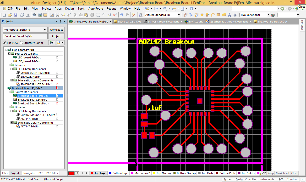
I also finished my first iteration of the breakout board design for the CapTouch Sensor:
5. WEEK SIX
5.1 July 30
Alice helped me calibrate the sensors today. One of them de-laminated during the process, pulled apart because the connection created by the tape to other objects proved stronger than the silicone bond. Alice said that's never happened before. It's most likely a result of the primer having gone bad even earlier without being as noticeably bad. Still, the other sensor survived the calibration and is now done. Below is the calibration setup:
I also talked with Hannah some more about the sensors. Hannah didn't think the breakout board was exactly what we wanted, but couldn't find anything that was. This means that I'm going to get to design a breakout board on Altium: Basically create a footprint for the captouch sensor and add wires out from each pin that connect to vias.
The last thing I did was finish the casting for two new underwater sensors, hopefully the primer continues to work for these as it has been doing so far. The new primer should arrive Monday night which will be awesome.
5.2 July 29
The second cast went much better this time around. One of them was perfectly aligned and had almost no missing silicone. The other one was slightly misaligned. Since it was the board with 16 individual capacitor sections, instead of one large one, this will affect the readings slightly. Still, I put rivets into the boards to connect the mesh with ground, and soldered a ground wire as well as a VCC wire to each. We can use these to hook the boards up to a breakout board for the capacitor to digital microchip that is usually on Alice's sensors but is not on these two. I sent Hannah the link to a break out board, if she thinks it will work it should arrive in time to test next week.
After wiring the boards, Hannah and I discussed the future of the project. She plans on conducting a few rudimentary tests underwater, in the hopes that we can publish a paper while I'm still around to be a part of it. She also considered adding shear sensing to the board. I figure we could add a back to the board that has shear fingers like the ones Alice uses, and combine the back to another board with shear fingers. The only thing I'm worried about in translating Alice's design from the regular sensors to these is that there is a lot less available space for the fingers. I don't know how many fingers the board needs in order to be accurate, but it's something I can ask Alice about later.
I began making more underwater sensors, in the hopes that after all the practice I can do an even better job this time. I'm starting to get the hang of what works and what doesn't work - for instance, getting the silicone to cover the mesh that extends out from the sensor part to the ground pin makes the rivet connection turn out a lot better.
5.3 July 28
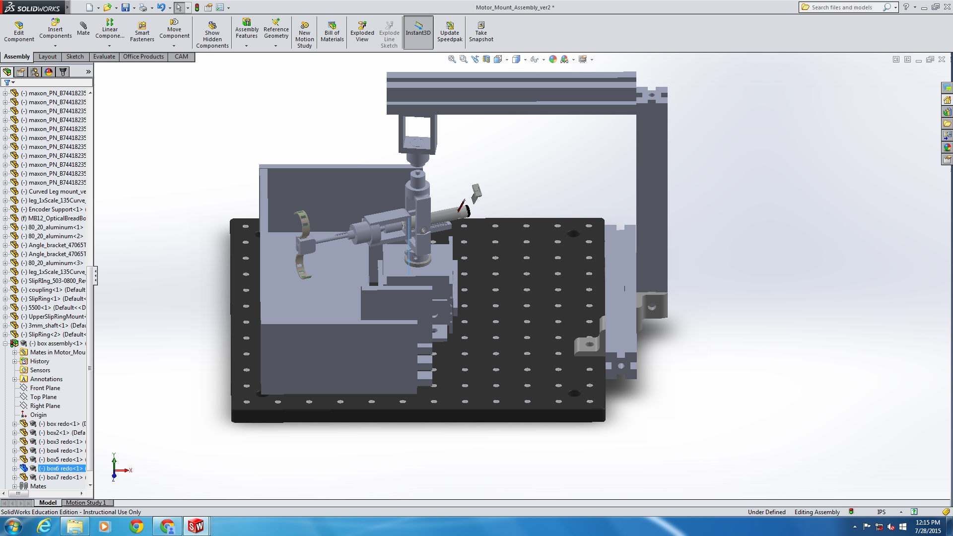
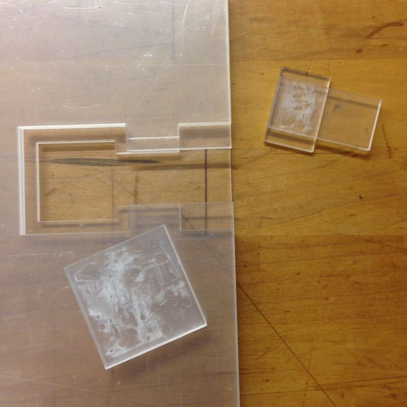
I did the second cast for the underwater sensors in the morning. Then I redesigned the box I had made for Alice so that there were two parts that fit together like a jigsaw, allowing her to use it without having to take her entire set up apart. Tae sent me a CAD file of the setup so I could check whether or not the box would fit beforehand. I fit one side of the box to the setup assembly file as shown below on the left. Although it took some extra time, I did catch several mistakes I would not have caught otherwise so it was worth it. The finished box, with chia seeds inside it for the experiment, is below on the right. The tape is there to cover up the slight gap between pieces.
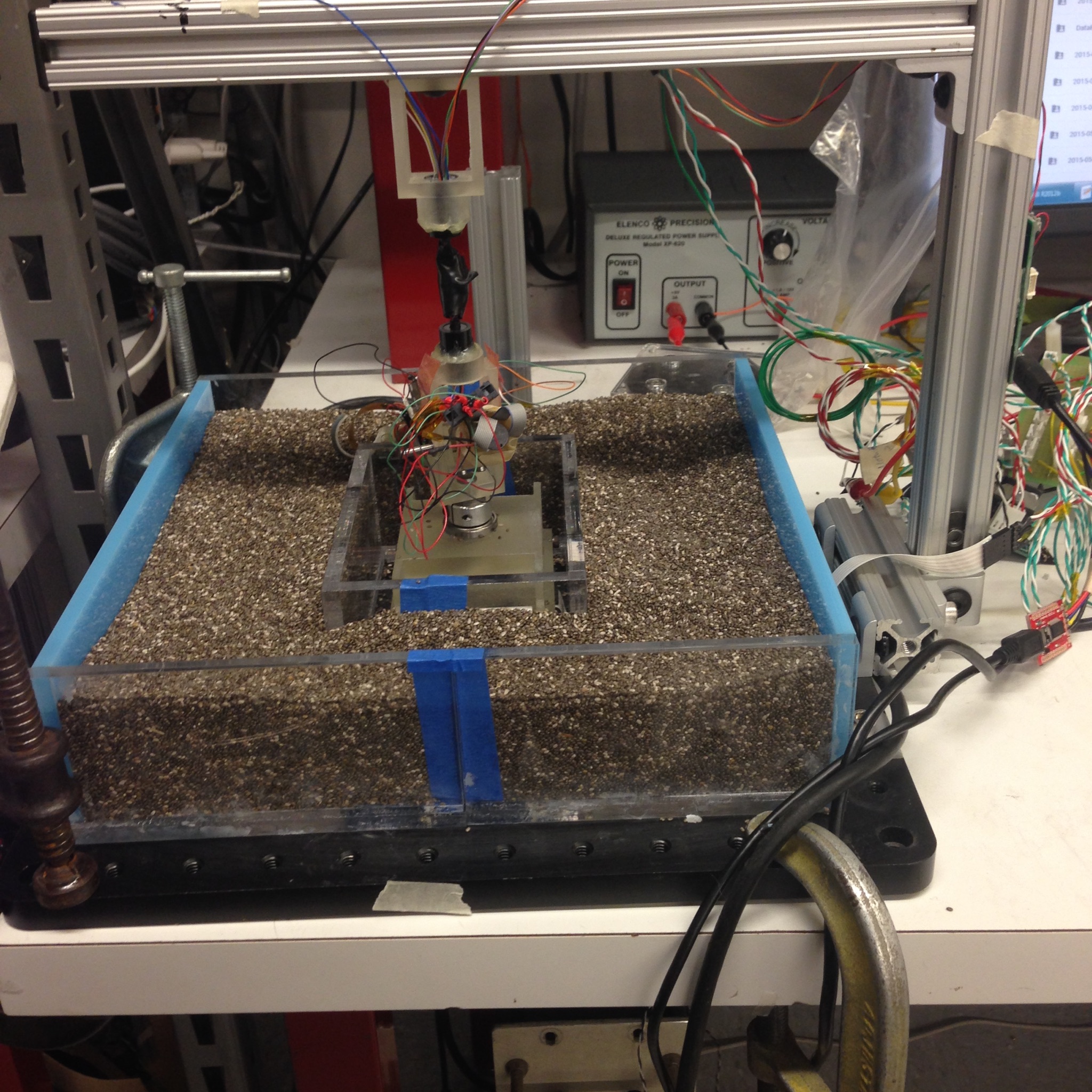
In the afternoon, we ran experiments with the chia seed surface. The data matched the data taken using the thicker carpet, which was interesting. Alice explained that typically on a surface the shear graph displays a sinusoid: a portion for deceleration as the foot hits the ground, and a portion for acceleration as it takes off. Both the thick carpet and the chia seed data lacked that deceleration portion. While we've been looking at step length as the best marker of whether or not a foot is slipping, I think it would also be worthwhile to check out whether or not the lack of deceleration, or even the smaller amplitudes of the sinusoidal motion at faster frequencies, means anything as well.
5.4 July 27
Despite the issues with alignment for the underwater sensors, one of them came out from the casting fairly well aligned. However, the actual grid had several small pockets on the surface missing silicone, rendering it still unideal for testing:
I primed two new boards, as well as two new boards for the normal layer of the regular sensors. I also glued the 1.2 mm dowels to the molds for the underwater sensors in preparation for casting, since the holes I'd designed in the molds for the purpose were spaced slightly too far apart to serve.
Unfortunately, after preparing for casting, Hao mentioned that the primer is getting old and is therefore no longer that effective at bonding the silicone to things. This helps explain why the normal grids haven't been working for me recently, which is useful, but since I already primed this round using the primer I have to just go through with it and see what happens. I'll have to ask Alice to order more primer - I would do it myself, but Heather usually takes a week or so to okay my orders so it'll probably be faster if someone else makes this particular request.
I re-cast everything in the afternoon, and will check on the casts tomorrow. I still don't know why the underwater sensor boards had pockets of missing silicone, but I have several theories. I'm hoping that it's either because the board wasn't pushed down enough and the silicone didn't reach all corners of the grid, in which case I'll clamp the board instead of placing a weight, or it's because the cast was left over the weekend without being taken out of the mold and that caused issues.
6. WEEK FIVE
6.1 July 24
First thing today I did the final cast for the two underwater sensors. I had decided to cut the fabric down to the correct size after the first cast, so that I won't have to after the second - this means that I won't have stray metal fabric bits poking out of an otherwise nice sensor, since after cutting them post casting on the first prototype I realized this was an issue. However, this meant i didn't leave the mesh in the mold between the first and second cast, which again made realigning it with the mold difficult. I won't know how well it went until Monday, but it definitely doesn't work as a reproducible, trustworthy process no matter the outcome. My plan for next time is to try to cut it with an exacto knife while it's still in the mold. This might cut the mold as well, but if I'm careful enough it shouldn't have a negative impact.
We had lab meeting at 10:30. This time Chris and Morgan presented. They both did a great job, and made what they were working on very accessible. I felt like I understood their thought process a lot more than I usually do during lab meeting, and I really appreciated the time they put into making that so.
After lunch, I made another interrogator board for Alice that she could program with the code for her three new flex sensor designs that came in this week. I also made the CAM file for the molds she'll need for these sensors:
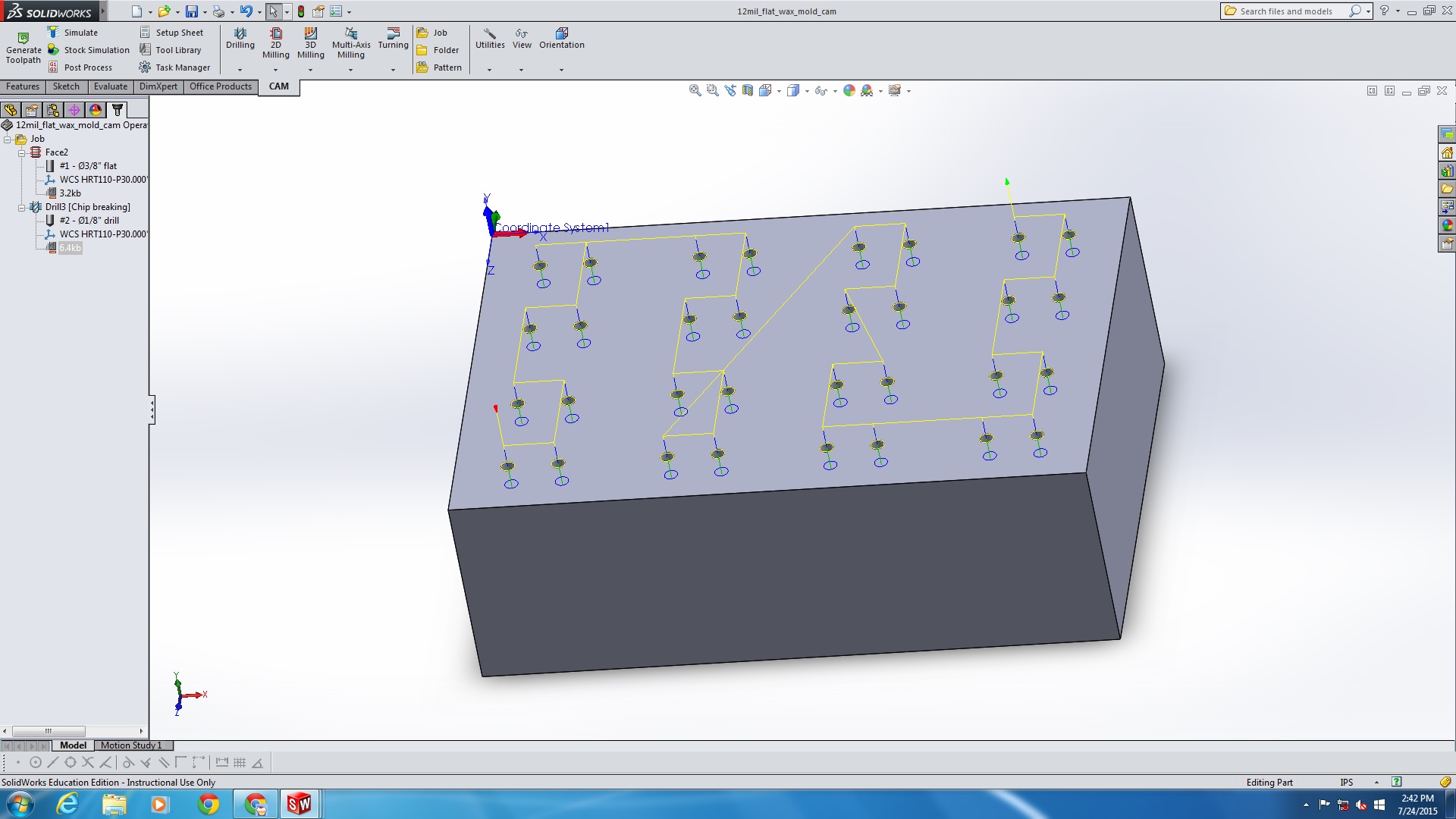
The CAM job only involves two tasks, facing and drilling the holes, but I'm still pretty proud that I was able to make it.
6.2 July 23
I primed two of the underwater sensor boards, then Alice walked me through the sensor code on MP Lab X. She explained to me that we couldn't actually add any code since the program was already at its space limit, but that by connecting the LED board up in the way that we did, it should turn on whenever the red LED on the interrogator board turns on. Since this light lights up for ten seconds every time the program starts, it will be enough to allow for the video to sync with the start of the program. I looked at the lines of code that program the red LED just so that I understood them, and then plugged in the board and ran the code. The green through-hole LED did in fact light up, which was a relief since it meant I really had designed the board correctly. I'd been a little worried, since Alice had never gone step by step through the design to make sure. It was nice that she trusted me to do it correctly, but it also made me very nervous.
Just before lunch, I headed over to the TLTL to cast the thin layer of silicone over the two sensor boards and to cast a second mesh grid.
In the afternoon, I helped Tae run experiments with the flex sensor. We got through collecting data for the linoleum surface, which involved running the robot at six sets of frequencies from 3 Hz to 8 Hz. When we switched from linoleum to thick carpet however the sensor broke down and we had to discontinue the tests. After that, I talked to Dave and Alice for a bit about how to go about adapting a sensor to fit the micro tug design.
6.3 July 22
I showed Hannah the underwater sensor mold from the other day. She wanted me to test it out, so I had to somehow attach the conductive metal to ground on the other side of the sensor. There were two options I could see: trying to solder a wire to the fabric or using metal thread. The first method melted through the fabric, and the second seemed to work. The only problem was that when we tried to test whether or not there was a short between the fabric and the copper plate before hooking it up to the computer, the multimeter tested a short sometimes and no short at other times. Since it wasn't a short between ground and VCC it wouldn't hurt the computer by trying to test anyway, so we did just that.
We got somewhat interesting results. It definitely worked when we applied force to all of the capacitor pads, however when we applied force to just one with a pencil tip, the program measured capacitance in the opposite direction. We went through several theories about why this occurred: I liked Hannah's the best, which was that the channels in between pads lifted up around the one compressed pad, which was a comparatively large change since the channels are so thin, and thus the net capacitive change is in the opposite direction. It shouldn't be as much of an issue when we use the actual board design that we're supposed to, since there's no copper layer underneath the channels. I think most of the problems we experienced should be fixed by that: For example, the shorting problem will be less likely to occur as well since only the grid with a very thick layer of silicone will be touching the pads, and no excess conductive fabric on the edges. Also, I plan on sanding less thoroughly. Still, I suggested casting a thin layer of silcone onto the boards before the other casts just as an extra precaution, and Hannah agreed that I should try it on two of the first four I cast. I'll do that tomorrow.
The boards arrived today, so I spent the afternoon cutting them out of their sheet. In addition, Alice, Tae and I checked on the normal post flex sensor cast from yesterday, and I redesigned the molds for the underwater sensor to account for two pins to position the PCB.
6.4 July 21
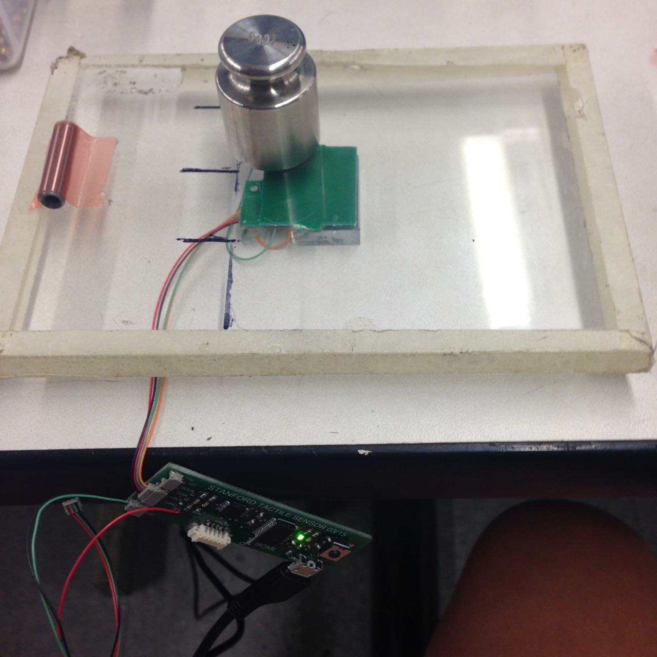
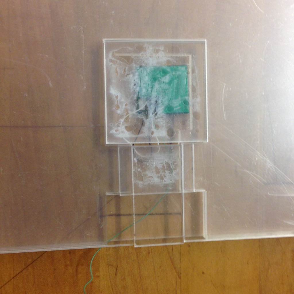
I cut off the side panels of the force sensors, which was a long and involved process of sawing. There has to be a better way, but I haven't thought of it yet. Then I conducted a more involved test of the sensors, which went beyond simply making sure every capacitor sensed normal force as I had checked before. Following Alice's instructions, I taped an acrylic panel to the top side of the sensor so that when we placed that side onto the table the electronics wouldn't be crushed. Then I placed a much larger acrylic panel on the other side, and ran the Matlab program. As the program ran, I placed a weight over quadrant, one at a time. This checked to see if any quadrants were more sensitive than the others. It turns out one or two were on each sensor. It's an easy issue to fix, as all it takes is adjusting for it during calibration. I also tested the shear force by pushing inward on each edge of the top pcb. Both sensors sensed shear pretty evenly from every direction. There was no bias I could see, though one sensor was slightly more sensitive than the other.
Below on the right is an image of the setup, and on the left is an image of the graph reading the signal from on of the quadrants as it measures the normal force of the weight.
After that I checked on the normal mold I cast yesterday. Despite adding many more weights than last time in the hopes of the silicon bonding more thoroughly with the pcb, there were still many patches where bonding was not so good. Alice says it might still be useable, however, but she'll check later.
I downloaded a C compiler that interacts with MP Lab X and began a tutorial explaining how to use a microchip to run a blinking LED program. I didn't finish, because in the afternoon Alice showed Tae and me how to cast normal posts for the flex sensor. The process takes several hours, which is why one should make as many as one can at one time. The supply we made from today should last several weeks. The process was essentially a longer version of the other casting processes, so I won't go into the details, but below is an image of the final mold with a thin layer of silicone being spread over it.
6.5 July 20
I laser cut the stencil for the LED board, as well as 2 different stencils for Alice's flex sensors. Then I soldered the board and made a jumper cable to hook it up to the interrogator board. The soldering this time around was a lot easier than it was for the force sensor board, and I didn't have to use the flux paste to redo anything. There's just something funky about the micro chip on the force sensor board which keeps it from ever reflowing correctly the first time, even when Alice does it. I have no idea what causes the difficulty. Below is a picture of the LED board connected to the interrogator board:
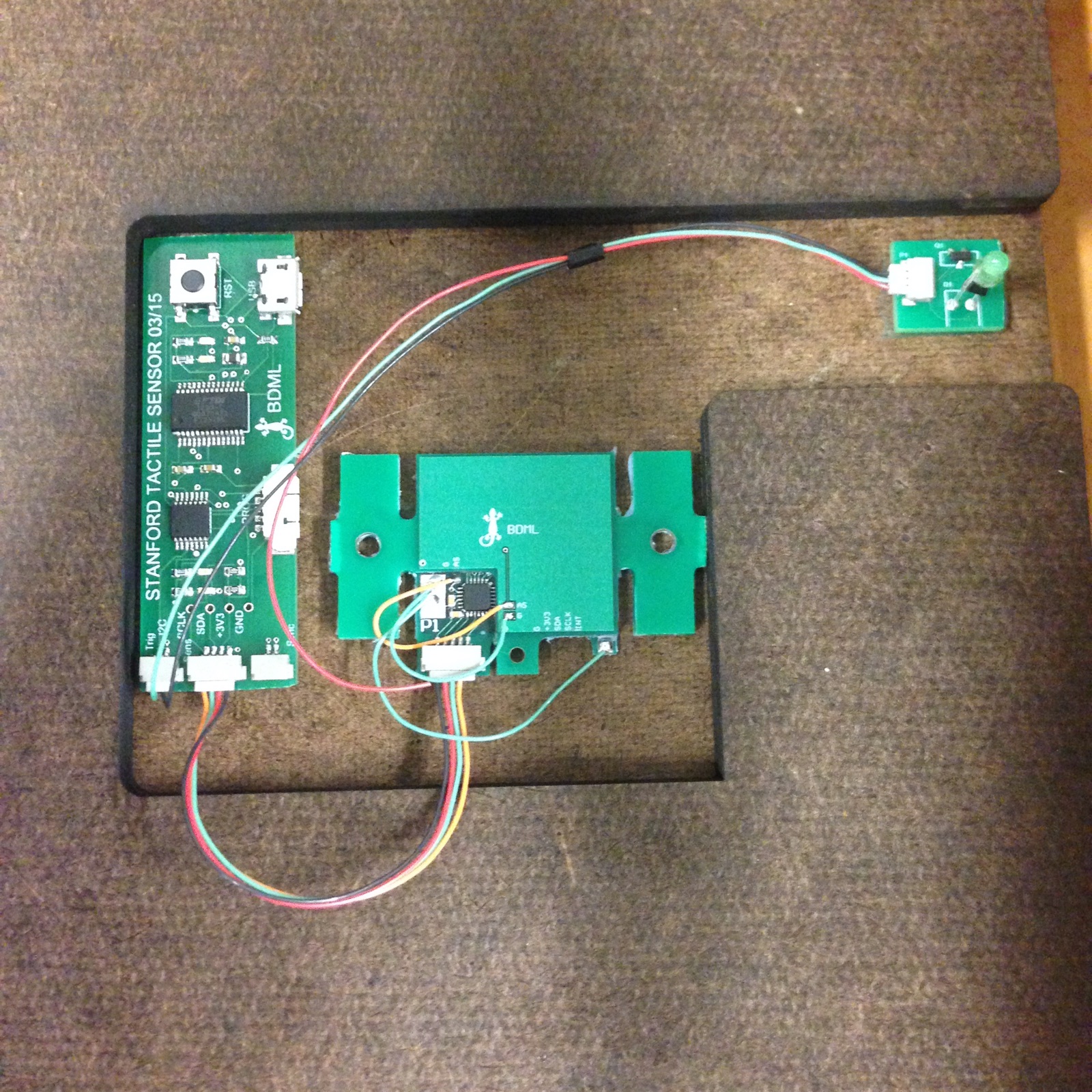
I want the board to sit below the surface to protect it from the walking robots, with the green LED protruding up through a hole. I've cut the hole, but I still want to add a tiny acrylic casing on the top which fully covers the LED. Since the acrylic is clear it shouldn't obscure the light as far as I can tell.
I also recast the normal layer for the third force sensor I'm making. Hopefully tomorrow Alice will have time to show me how to test the normal posts that I've already cast.
7. WEEK FOUR
7.1 July 17
I cleaned off the grid layer of silicon from the PCB so that it could be recast, however I couldn't find the primer so I couldn't recast today. Alice had a chance to look at the shear cast from yesterday and said it was really good though.
Lab meeting lasted until 11:30, then we had the BBQ. Afterwards, I remade the box Alice requested because I had misunderstood what she needed. Instead of fitting a thin box over the platform she already had installed, she intends to entirely remove the platform and most of the structure, so the box needs to be tall enough to reach the suspended foot from the ground.
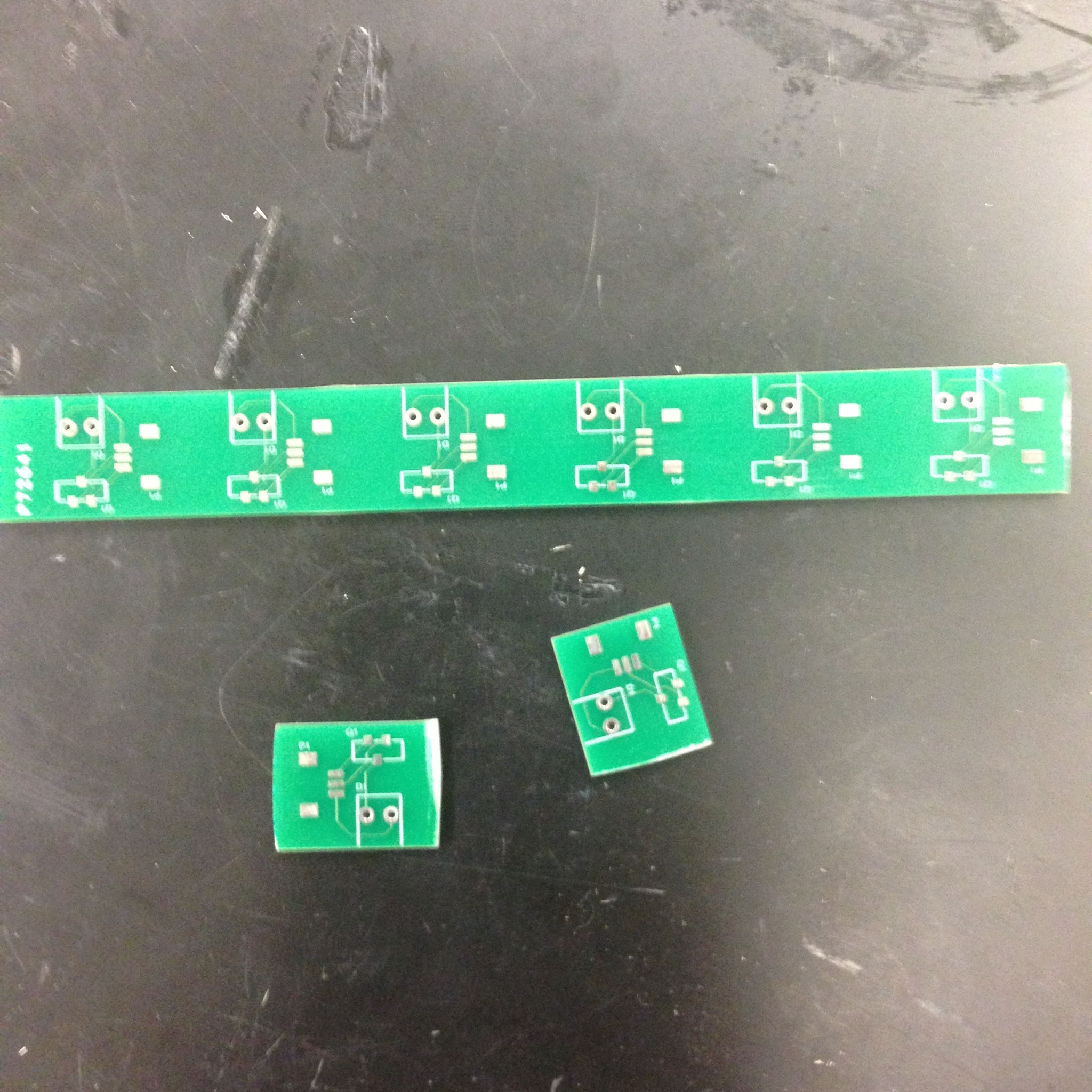
I finished my final design for the ME112 board, including sanding some of the pieces so that things fit together more smoothly. I've checked that all the wires, boards and USB connectors can fit in the room provided inside the board, and I added a few extra touches such as small rubber pads so that it doesn't get scratched on the bottom. So that part of the project is done. My LED boards also arrived in the mail today, so I was able to cut them out into individual boards and create a stencil for the soldering. I'll laser cut the stencil and solder Monday. After that, the only remaining task is to calibrate the sensor and cut off the side panels that contain the dowel pin holes. This last task is slightly trickier than it sounds since we have to be very careful not to harm the board.
7.2 July 16
The first thing I did was go through a tutorial on programming in C. Then I considered how best to connect the nmos gate to a microchip pin that can be programmed to cycle through high and low voltages. My choice was a pin on the FT232RL chip which the guide said could be used for MOSFETS and programmed using FT_Prog, but when I spoke to Alice she said we should instead use the other chip and use MP Lab X to program it, so I looked at MP Lab X for a bit.
While we discussed this, Alice and I left to buy more acrylic, silicone, and Duron. When we returned, I headed over to the TLTL to laser cut the box Alice wanted as well as check on the casts from yesterday.
As you can see, the underwater casting seemingly turned out well, although I don't know for sure how it was supposed to turn out. The normal casting did not go so well - the silicone layer doesn't appear to have attached that well to the PCB, and thus it isn't usable. The shear layer on the other looks okay, but I'll need a second opinion. I began cutting the shear layer out of the excess silicone, and also ordered the remaining parts for the ME112 sensor board.
Alice would like the third sensor to be completed by Monday so that Arul can cast sticky adhesive onto it then. Hopefully when I do the normal cast again tomorrow it works out, since otherwise I won't make that deadline.
7.3 July 15
Today I got the matlab program from Alice that allowed me to check whether or not the sensors were working electronically. Both the two new ones I made and the extra board for Hannah were all working, so I was able to prime them for casting. Alice also asked me to design a box that would fit on top of the contraption she uses to test her flex sensor, which will hold poppy seeds and allow her to test the robotic foot on that surface. Poppy seeds act in much the same way sand does, so it's basically a test done on that family of surfaces.
I had to wait for the primer to dry for a few hours, in which I started to familiarize my self with programming in C. I probably won't learn enough to actually write the code that programs the LED board, but this should help me understand it. After the primer dried, I was able to check on the normal posts and then cast the shear layer and a normal grid layer for the two new sensors, and do the second cast for the underwater sensor prototype. The normal posts turned out well: The thin layer of silicon was a little more uneven than when I did it with Alice, and the fiberglass sheet wasn't as flat as a PCB secured by dowel pins would be which did affect the casting, but if we hook up copper to the back of fiberglass we should still be able to test the effectiveness of the design. From appearance alone, I'm betting that the medium density post designs will perform the best.
A note on the underwater cast - it was unexpectedly hard to re-line up the mesh with the grooves in the mold. In the future, it might be a good idea to either do the second cast immediately, without taking the mesh out of the mold, or in the beginning cut holes in the mesh that fit over the dowel pins. That way it will hopefully re-align more easily.
7.4 July 14
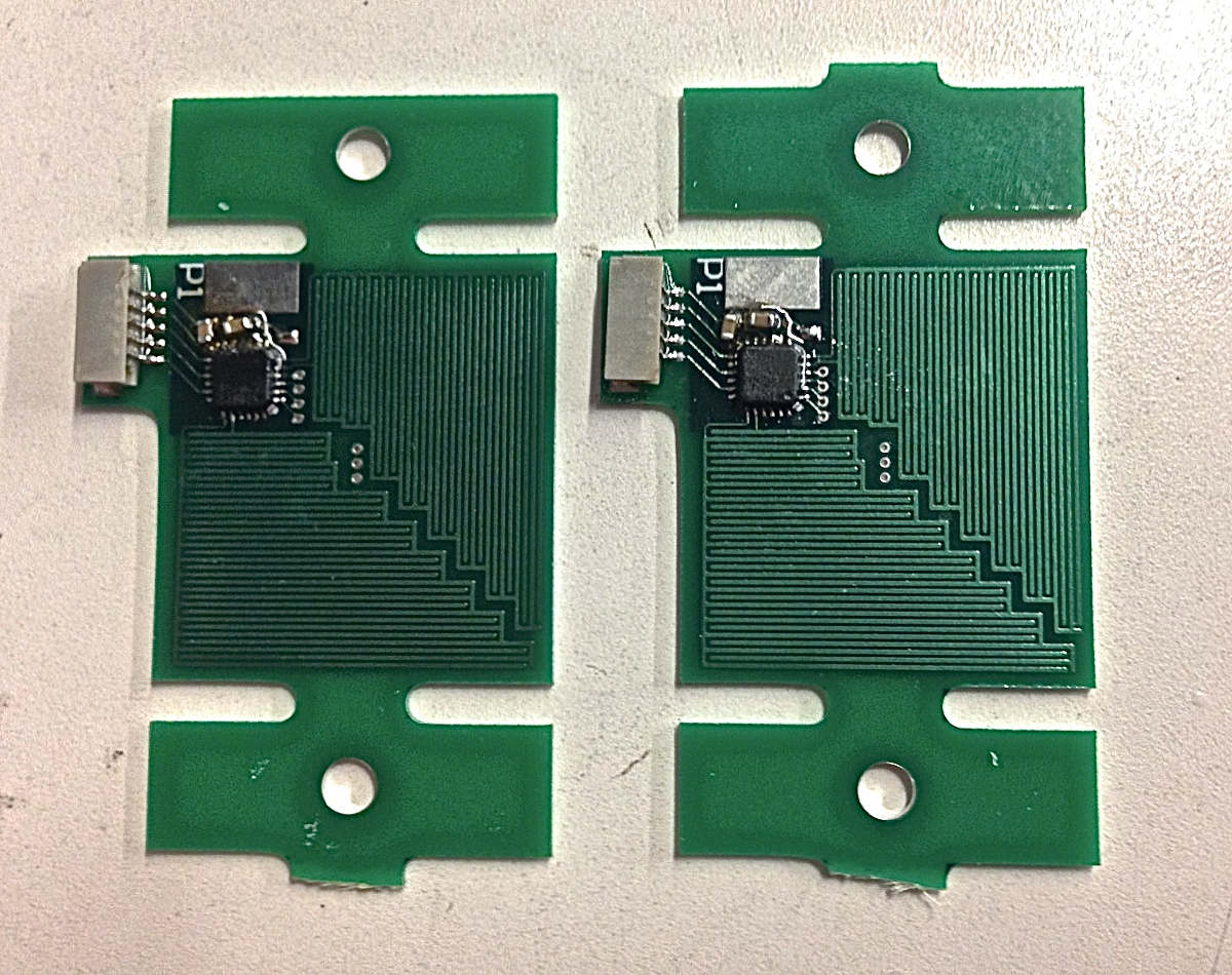
I made a new organizer for the wires by the soldering station first thing, then checked on the casts we did yesterday. Surprisingly, both the two sensors and the prototype came out well! So now I have two force sensors finished and ready for calibration. Alice can't get to the calibration until next week when she's done with the flex sensor, but still very satisfying:
On the left are the two sensors, on the right is the prototype casting for the underwater sensor. I soldered a board today that I can use tomorrow to cast it onto, to test out whether or not the mesh design works. It's one of Alice's earlier designs for her force sensor board that she no longer uses, but it should work for this.
I also primed eight fiberglass squares and cast all the normal post designs. Tomorrow we should be able to see what the highest density of posts we can successfully manufacture is based on which of the eight turn out.
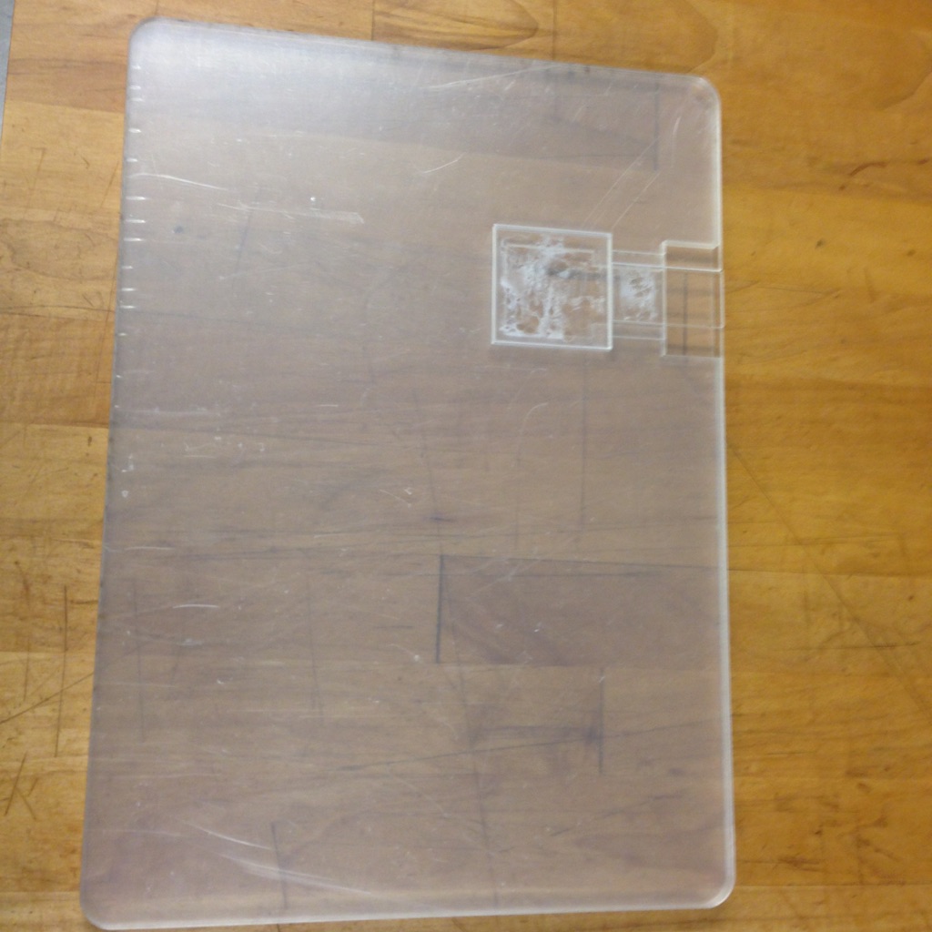
7.5 July 13
I laser cut a third iteration of the force plate design. This iteration improves on the last one because there is no small piece that slides into place and might get broken or lost - instead, the entire top is removable. This will also allow the top to be replaced easily, in the event it shows a lot of wear from many different surfaces being taped onto it and then removed. The other notable changes are that there is a separate place for the LED board beneath the surface, which will later on have a hole above it where the LED can poke through, there is a slight gap between the plate above the sensor and the surrounding surface, and the board is even more lightweight. This weight reduction comes from a greater number of material removed as well as a lighter material - Duron.
I typed up a sheet detailing how the force sensor works as well as the surrounding structure. All it needs now is an image of the setup.
Just before lunch I primed the PCBs for the last cast, so we could do the cast in the afternoon. Along with that cast, I also tried to do a first cast for the underwater sensor, since the plan to simply mash the metal mesh into place yielded inadequate results. The cast involved taking a small square of mesh and spreading the blue silicon mixture over it, then squeegeeing the silicon until it formed a relatively thin layer. The next step is to take the mesh and sandwich it between the two 3D printed parts I designed, which are aligned with the same dowel pins Alice uses. I was lucky in that my tolerancing for the pins was correct and also translated well to the 3D printed material. The last step is to clamp the whole arrangement together.
I'll be able to check on both casts tomorrow a 2. We doubt the underwater sensor cast will cure the first time, since both very thin films and 3D printed parts are notoriously bad for curing, but we're really hoping the regular force sensors cure properly. Alice says the rest of our work might still be salvageable if not, but that's only a maybe.
The rest of the day I spent soldering two new PCBs for two new force sensors. These will incorporate Alice's design for silicon posts rather than a silicon grid so that we can test the efficacy of that in comparison to the usual design.
I ended by finishing up the organizer I built for the wire coils. Alice liked it and asked if I could make another one tomorrow.
8. WEEK THREE
8.1 July 10
There were two meetings today - one a force sensor meeting where Alice and Tae presented their findings, and we discussed what part of the data should be examined in order to define bad slippage conditions versus good conditions. Mark suggested looking at stride variation. The second meeting was an entire lab meeting.
Other than the meetings, I spent the day checking on the normal mold and working on the aquatic sensor project. The normal mold turned out fine. It was a little uneven but Alice said it would work:
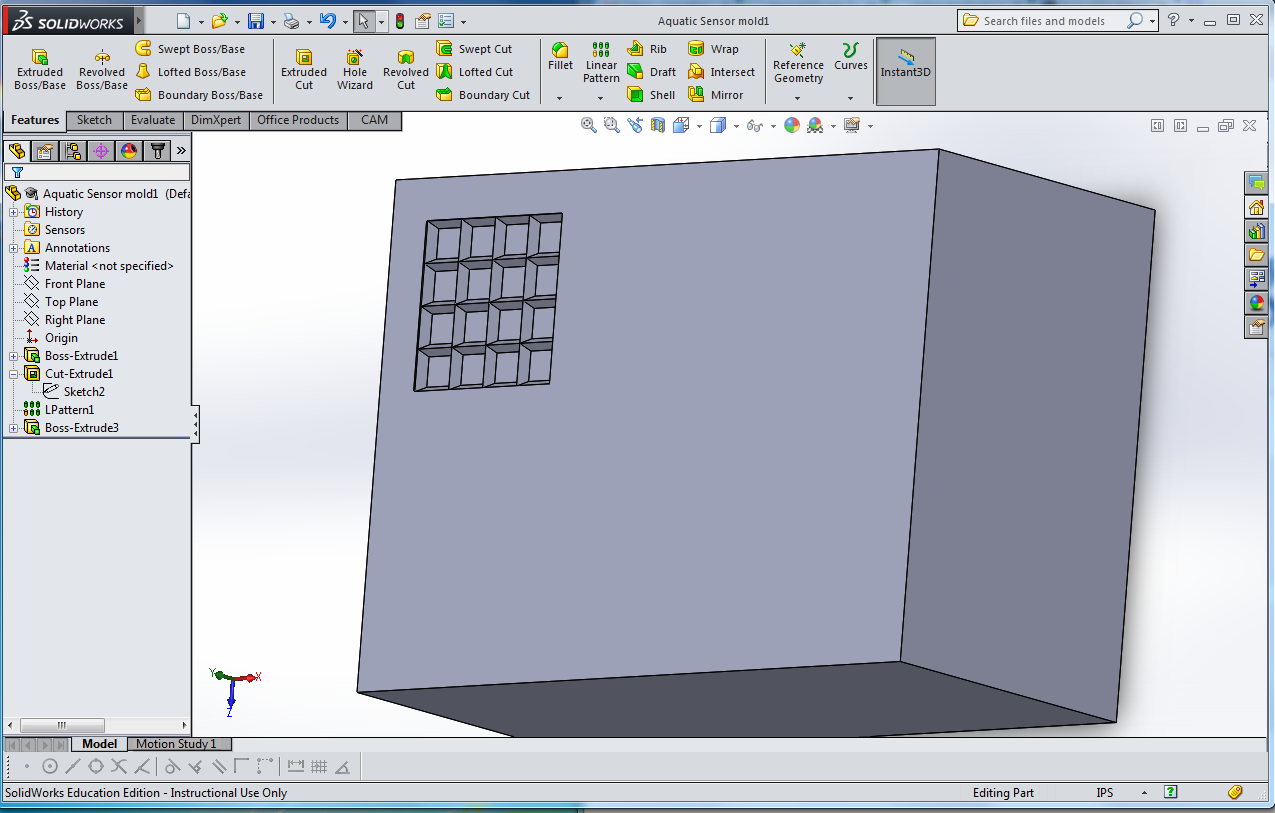
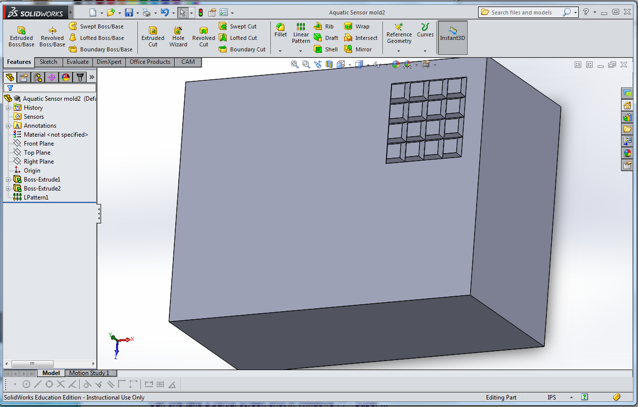
That leaves us with just one more cast before the sensors are finished and ready to test. In regards to the aquatic sensor, I finished the SolidWorks designs for the mold. The plan now is to use a conductive layer of metal mesh instead of rubber, which Hannah thinks can be pressed into shape using the molds, render a first casting unnecessary - if it doesn't end up holding the shape, however, we'll just spread a thin layer of silicon over the mesh before pressing down and cast it that way, Before doing a second silicon cast. To prepare for this, the next step is to work with Hannah to make the CAM file, and run it, while also working on a design for the 16 capacitor board. I started on that today, but will need a few more design parameters from Hannah before I can continue.
8.2 July 9
I sent my board out to be fabricated today, which involved routing it, checking for design problems using a tool in Altium, creating the gerber and NC drilling files, then checking those files all together by submitting them to a free program linked to the fab house I planned on using. The free program freedfm, reported that the traces were .1 mil, when they read the correct 6 mil in the gerber file, which meant the board didn't pass the test. However, Alice said that since the gerber file had the correct value, we should send the board anyway and the company would email us if there were issues.
After ordering the board, Alice and I checked on the normal test casting we had done yesterday. It had worked out quite well - 3 of the 4 boards had usable layers - so I primed the actual normal boards so that we could cast them two hours later. I did the priming myself and the casting, so crossing my fingers that it works. Luckily the normal boards aren't very expensive and not attached to the rest of the board, so a mistake won't cost the entire board we've made thus far.
I also helped Arul make the third mold so that we could experiment with Alice's new normal design that involves posts instead of a grid, and began working on Hannah's aquatic sensor idea. I quickly realized that the design would require an adjusted board design, as Hannah suggested using a 16 capacitor design rather than 4. How I redesign the board thus depends on whether or not a double casting for the top silicon/rubber layer will succeed. I design a two part mold for the process: Two pieces fit together, offset by some arbitrary thickness, one side with a grid extruded into it and the other with a grid extruded out of it. The rubber would be poured into the former and then the latter side would be pressed down onto it. After that casting, silicon would be poured into the pockets of the rubber grid as a second casting. If this doesn't succeed, Alice suggested instead designing a flex sensor as opposed to the rigid sensor, which wouldn't require double casting.
8.3 July 8
We checked on the silicon cast first thing to see if the silicon cured properly. It did, and we cut the boards out of the silicon using x-acto blades - the process was tricky because we had to be careful not to pull on the silicon layer sandwiched between the two boards in any way. While we were in the TLTL (the School of Education Lab), we also did the practice cast for the shear layer.
I spent the rest of the day on two projects: One, making adjustments to the laser cut parts for the force sensor plate to make the overall design both lighter and sturdier. Two, reading Dave's papers on micro tug robots in preparation for a project Alice wants me to tackle after we complete the force sensor plate. This project involves finding a way to attach one of our force sensors to one of Stickybot's feet and evaluate its performance there. Alice suggests using a servo motor to apply force to the sensor, although the addition will shift the weight of the foot in question farther from the wall which could be tricky.
I also watched a video on how to create gerber files for a PCB in Altium, and the rest of the process involved in sending a board off to be fabricated.
8.4 July 7
I worked with Alice to improve at Altium, then made some adjustments to the JST connector footprint and made the final versions of the other two component footprints, after which I placed them onto a board. I asked Heather to purchase the two components I don't already have, which should arrive in two or so days. The board design still needs to be sent out, but I'll wait til tomorrow when Alice has more time. The board looks like this so far:
Alice and I were also able to finally cast one of the silicon layers for the two force sensors I've been working on. We only prepped the shear layer and not the normal layer as well because the molds had never been used before, and the normal mold still had grit in the design that would affect the casting. I suggested we do a practice cast we didn't care about to try and clear out the grit first, then do a real casting later. But luckily the shear mold was fine and we were able begin the curing process for that layer. We'll check back tomorrow to see whether or not it succeeded.
8.5 July 6
I got bootcamp to work on my computer so I was able to download Altium, as well as the programs I'll need for testing the force sensors: FT-Prog and MP Lab X, among others. After downloading programs, I watched a combination of ME 218 lecture videos and online tutorials to get myself acquainted with Altium. From there, I was able to design the JST connector component and switch over the PCB design entirely from Eagle to Altium. I also made several practice component schematics for the LED as well as the nmos. I don't know which specific company and part number I'll be using for those, so I won't make the final designs until I talk that over with Alice.
9. WEEK TWO
9.1 July 2
I made a jumper cable to connect the interrogator board with the force sensor, then discussed some final tweaks to the force plate design with Alice then Mark. I was able to laser cut the finished board in the afternoon. It looks nice, but the black acrylic shows dirt and scratches more readily than I would've liked.
I also got started on designing the PCB for the LED that I'll later attach to the board. It's a very simple board with only 3 components: a through-hole LED, an nmos MOSFET and a JST connector which I'll use to link it to the interrogator as well. It shouldn't be too difficult and I'm excited to design my first PCB. However, I'll have to learn Altium in order to create a solder map for the JST connector, since there isn't a pre-made package on Eagle and Eagle is incredibly difficult for creating parts.
The board should be done by the end of next week if all goes well. To accompany it, I created a few PowerPoint slides to explain how the sensor works. I might also write-up a short document since I'm not sure which method of conveying information is better.
9.2 July 1
I laser cut a number of plates for the flex sensor test setup, which we can attach the different terrains to and trade them out as we test. Then I learned how to test the force sensors and interrogator board to make sure they worked electronically. It involved a number of programs that won't work on my mac computer in order to download a working program onto the board, so I'll only be in charge of running the matlab code on an already programmed board when I test.
Our tests showed that both the interrogator board I had made and the flex sensor worked. Now fairly confident of my ability to make a working PCB, I decided to remake the two force sensor boards I made at the beginning of last week, since they're a little messy. We'll do the casting for them tomorrow.
I spent most of the afternoon on the remakes and on buying new supplies at the physics shop, though we also got time to complete a few test runs of the testing machine. We tested the curved foot design for robots on acrylic and sandpaper. There were some problems with the data due to the springiness of the setup so we added foam to damp it, as well as some problems with slippage at very low RPMs where we would not expect it as much. Otherwise the tests looked good.
9.3 June 30
I spent the morning redesigning the ME112 project to Mark's specifications. I designed the cell phone holder to be adjustable, but Nina suggested using the gecko adhesive instead as that would accommodate every size phone as well. The idea was quite good and I'll probably just do that instead. Alice bought the acrylic so I'll be able to make the final print sometime this week - as soon as I run the new design by both Mark and Alice.
I finished the second Eagle tutorial and started on the third, and printed out a few interrogator board stencils. When Alice got back from buying supplies, I moved on to the project she and Tae were working on for the day: getting the rotating contraption for testing the flex sensor on a curved foot up and running. Alice needs to test the foot on a wide variety of terrains, with varying frictional coefficients, so I helped fit the various surfaces to the testing contraption. Below is the contraption without anything fitted to it. I'll take more pictures later when we begin to test.
9.4 June 29
I worked in the School of Education again for the morning. I cut out printed circuit boards with the band saw and created stencils for them. This was the first time I'd made stencils completely on my own without Alice present. It went very successfully, and when we met up again we agreed to do the soldering in the afternoon.
I had some time left until lunch, so I made the first prototype of my layered force plate idea. I mainly focused on prototyping the section with the force sensor in at as well as my slotting mechanism, ignoring for now the cell phone attachment. The pieces fit together quite well and the slotting mechanism worked. The only problem with fit was that the force sensor itself was a hair taller than I anticipated. I can probably get away with sanding down the plate resting above it in order to adjust for this. I might also add something to surround the force sensor, such as foam, which would keep it from sliding around in its pocket, and maybe a piece to support the side of the slotting mechanism which is floating a bit.
The next step was to design and prototype the cell phone holder. I decided to make a smaller prototype without remaking the board so as to save acrylic. After all, everything would need to be redone any way for the final product - I want to order black acrylic for that, solely for aesthetic reasons. I'll have to talk it over with Alice, but I think aesthetics can be very important.
Since Alice wasn't ready to solder after lunch, I worked on the second Eagle tutorial for a while. I also spoke with Mark about my prototype. He suggested enlarging the board to two feet long and placing the square at the fifteen inch mark, as well as rounding a few of the sharp corners to reduce chance of breakage. When Alice was ready, I set about making my first interrogator board. She showed me where a few of the pieces were, then left me to find the rest on my own as well as take care of the soldering. I was quite proud when I finally finished. Below is the board:
10. WEEK ONE
10.1 June 25
The whole lab went on retreat today to the beach. We jogged on the beach, played football, people went for a swim, and we grilled hamburgers. It was a fun day. We wrapped it up with a meeting where each member of the lab outlined their goals for the summer. I had four goals:
1) Help Alice with her work on flex sensors and attaching those to walking robots; 2) Learn Eagle and Altium so that I can design my own circuit by the end of the summer; 3) Improve with creating jobs through cam, and being able to set them up on the CNC; 4) Complete the force sensor plate for ME 112 in the next 2-3 weeks.
10.2 June 24
Today was the big clean for the entire lab. It took about 4 hours to do, but was pretty satisfying by the end, since you could finally see all the table tops and wipe them down. I never thought we'd reach that point.
After finishing, Ian and I drove to Costco to purchase supplies for the retreat tomorrow. When we got back, I quickly redesigned some laser cutting patterns for the second iteration of the force sensing plate. In order to laser cut everything and still make the sensor and it's covering plate easily removable from the rest of the structure, I decided to laser cut 4 layers of acrylic, each 1/8" thick. This allowed me to make a slot inside the board for wiring, as well as a slot that a second piece of acrylic slides into. This second piece can be easily removed, at which point the sensor and it's plate can also be removed. With these designs, I took Ian over to the School of Education and showed him how to use the laser cutter. I got halfway through making my design, at which point the laser cutter unfortunately stopped working - the computer ran out of disc space, and despite deleting files wouldn't print again.
We gave up on that project for the day, which I'll hopefully have time to take up again Monday. Since we were at the School of Education anyway, I decided to spend a few minutes on constructing the shelf Alice asked for, which will help organize the wire supply by the soldering station. We sawed all the wood for the shelf, but drilling the holes is another task I'll have to finish Monday.
10.3 June 23
In the morning there was a meeting with Mark, where we discussed the schedule for the week as well as the force sensor project. It turns out a force sensor array isn't necessary for the force plate, and it should be redesigned as a single sensor inset into a larger platform that the robots can walk across. The design will be much simpler, and the only difficulty I can see in simplifying is that the size and simplicity of the part make it more suitable for laser cutting rather than milling now, which means the design can only include features that can be laser cut. Other than that, I also need to add in a mount for a cell phone at a distance that the phone can easily focus on the space above the force sensor, as well as a blinking LED that keeps track of time. The code should be almost as simple as the design, however I've only ever worked with Arduino and am unsure if a hand-made PCB runs on that.
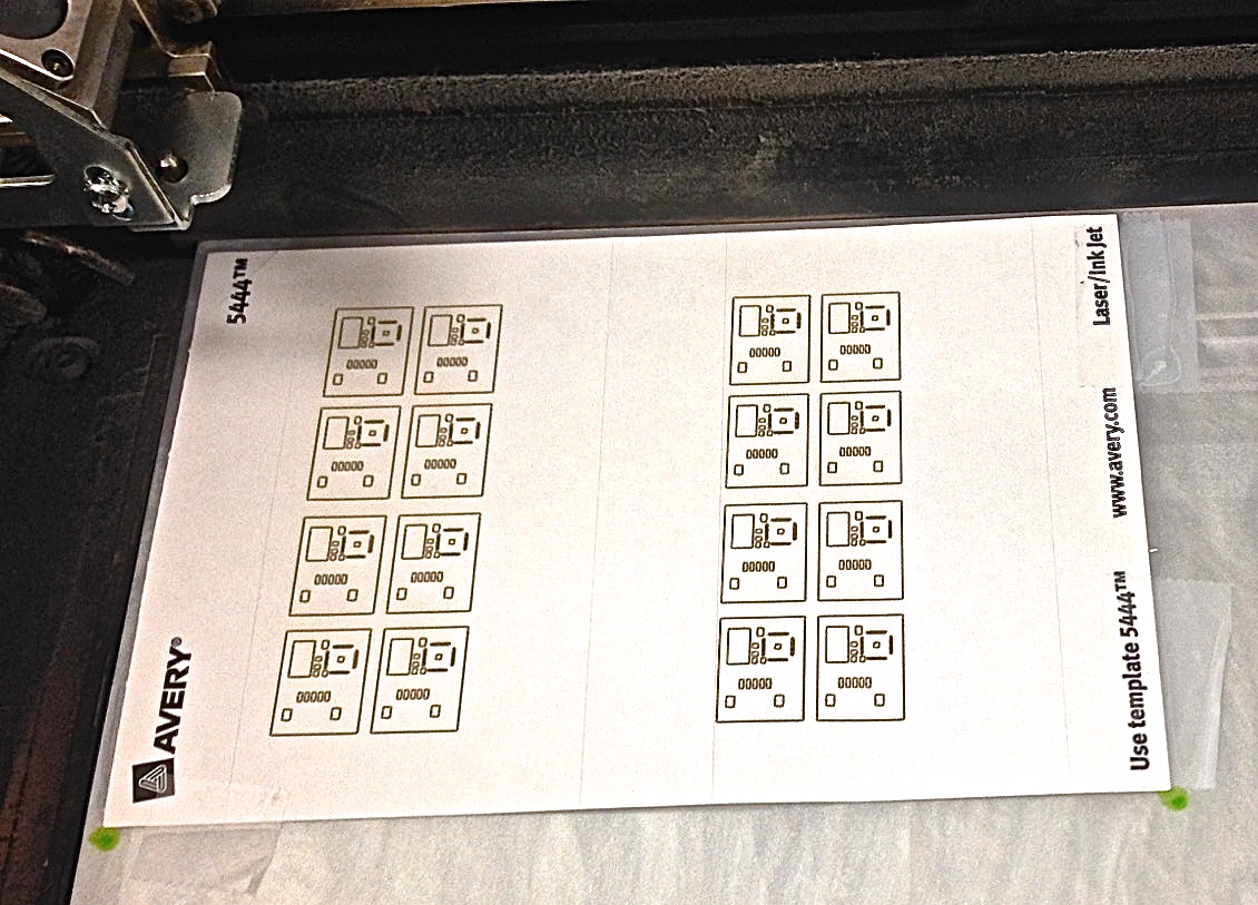
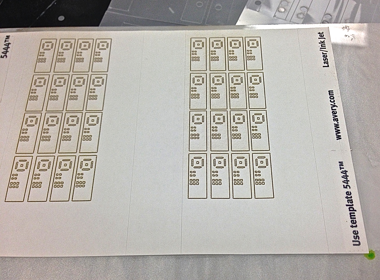
The meeting ended a little after ten, at which point I headed over to the School of Education lab with Alice. She taught me how to use the laser cutter there - mainly how to manually focus which I'd never done before - and then I printed the shims and stencils we'll need for the circuits:
After lunch I attempted to make my own PCB using the stencils I'd printed. Which went rather poorly the first time; I couldn't get my hands to stop shaking for some reason. The second attempt went a lot better. I was able to apply enough paste and align all the pins properly. The problem then was that the solder paste didn't reflow in the microwave. I decided that instead of wiping it all off and redoing it, I'd instead use both the heat gun and soldering iron to fix it up. As far as I can tell it looked okay after that, my only worry is that the extra heat might have fried either the chip or the capacitors. Or both. I'll have to wait and see.
The rest of the day I spent completing the Eagle tutorial.
10.4 June 22
I met with Hannah first thing to discuss the underwater sensor project, and got all the documents on that to look at as soon as I have time. She already has a hypothesis for making a sensor underwater, which addresses the main problem of the current force sensor: that there are air pockets contained within the silicon layer which won't react well to pressure changes. The goal for me is to build an up and running sensor based on this model so that we can test the hypothesis.
After discussing this project with Hannah, I met with Alice regarding my main project. She introduced me to the program Eagle and sent me a tutorial that I'll try to walk through tomorrow. She also gave me a demonstration on the soldering process she uses for the circuit boards in the hopes that I'll be able to make my own interrogator board and force sensors this week. The process was a far cry from what I've done previously with solder, as it involved using a paste composed of solder chips instead of a solder gun, which you then heat up in the microwave until it 'reflows.' That is, melts into the nicely finished solder that you see on circuit boards. In order to set myself up to attempt the process on my own, I'll be laser cutting outline stickers for the boards later this afternoon - these act as guides for the solder, by covering up certain parts of the board and exposing others.
The rest of the day was spent familiarizing myself with more of the processes I'll be using in the upcoming weeks. Firstly there was the silicon molding, which Arul introduced me to:
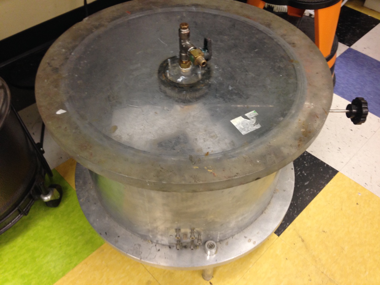
The first step involved mixing the silicon from its separate components, and then placing that mixture in a sealed vacuum chamber to remove air bubbles (the set up for that can be seen in the picture on the left). Then the liquid silicon is poured over a mold and once again exposed to the vacuum. We completed the process by placing a glass panel and weights on top of the silicon, which can be seen on the right.
This tied in to the next process we went over, which was how to use the NC machine. Arul and I made the CAM programs for the three different molds that Alice plans to use for the force sensors. One to help with the placement of the boards in regards to measuring shear forces, one with the current design used for silicon molding, and one with a new design she believes will more accurately measure area changes. We ran through the programs on the machine one by one, using easily machinable wax for the molds:
The last mold program took an especially long time to run so I worked in the mean time on SolidWorks, beginning my design for the mechanical portion of the force sensor array. I'll continue with that until it's time to move to the laser cutter.
10.5 June 21
Today was the first day in the lab! We got introduced to all the projects that are currently in progress, including the underwater robotic hands, perching, a kite robot, and various projects on sensors. I'll be working with Alice and Tae on building a force sensor plate to measure the ground reaction forces for crawling robots. I also hope to have time to work on developing an underwater sensor as Hannah suggested, as it is along the same lines of working with sensors.
For the force plate project, I'm going to be responsible for the mechanical part of the force plate. This means I'll be focused on designing the actual plates and the backing on which the array of sensors rest. I'll also be making the actual force sensors, which includes soldering and silicon molding. To start out, my goals for the day are to read the paper that has already been published on the force sensors in order to understand them better, and to take the CNC tutorial, which I'm really excited about since I've always wanted to learn how to use a CNC.