Categories: SummerBlogs, MedicalRobotics
Zulekha's poster for final SURF presentation:

July 27 - July 31
FBG and Mitral Valve
This week again I am improving and building my designs on both projects.
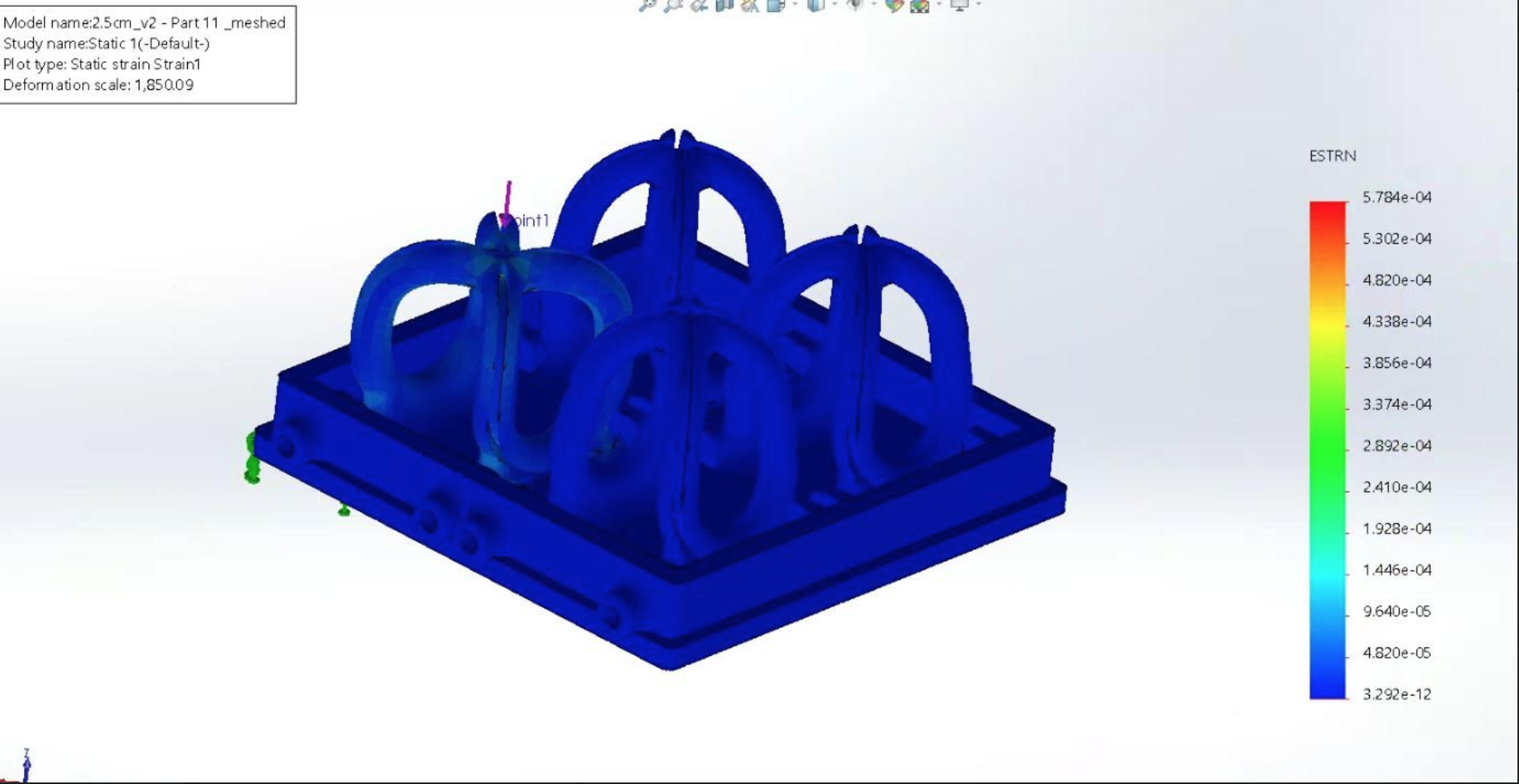
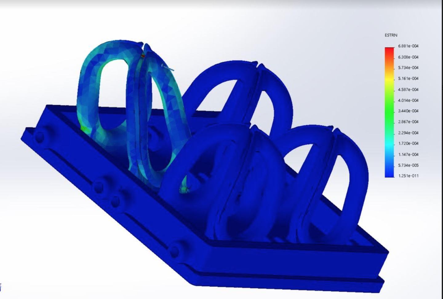
FBG Project Updates: After adding the holes I saw a great increase in strain. However, I added the holes parallel to the pillars and some problems that could come from this is an uneven distribution of strain across the sensor as well as when pulling strain value I could be pulling increase strain concentrations within the holes and not what is really around the sensor. My goal for the rest of the week is to add the holes perpendicular to the pillar as well as increasing the hole diameter
Mitral Valve Project Updates:
July 23 - July 25
FBG and Mitral Valve
This week I will just be continuing on improving the FBG design and building on the Mitral valve fatigue set-up.
FBG Project Updates: As discussed this week I am separating my results from strain value between sheer and normal force applied. However, after a meeting with Dr.Cutkosky, we discussed other design elements we could add and decided perhaps removing material near the sensors would be effective. One way to do this was to remove material form the pillar near that area or add holes. Adding holes we have seen to have been effective in other projects such as the biopsy needles (need to add project link), therefor with this concept in mind I will incorporate adding three holes in the sensor are on the pillars with hopes that the strain will increase evenly in this area.
Mitral Valve Project Updates: Currently I am working on improving my skills within On-Shape. With Sams help I am learning how to design a little more complex pieces, as well as how to plan a design in your head before CAD-ing. It's been really interesting and a great experience to learn to CAD more in depth. Design visual updates I will add soon!
July 20 - July 22
FBG and Mitral Valve
This week my focus is to continue improving the FBG structure and collect more results to really show if the new design ideas we are adding are effective or not. For the mitral valve I will continue to get the FEA fatigue working as well as designing the mitral valve experiment set-up.
FBG Project Updates: After having multiple designs for the FBG Sam and I brainstormed and reviewed our current results to discuss what element designs we should keep and get rid of ones that were not as effective.
The current additions we found effective were: -Decreased Diameter -Increased base -Shallower grooves
Ineffective additions: -Adding struts -Increasing strut size
We came to these conclusions from the FEA results. However, we are still working to improve the design. I also realized that the data I was pulling from each element may not be as effective as pulling all the values on the panel where the sensor will be, and then averaging it out and comparing those results. I also need to separate the values I pull from when I apply a sheer force only and a normal force. This is important because we want to see that when a sheer or normal force is applied the strain value is around the same magnitude. If they are severely different that means that the structure is not as supported for all types of force directions.
My goal for this week is to separate the the strain value results from sheer and normal forces applied to see the impact of the design elements on these two forces. I will also be brainstorming more ideas to improve the FBG structure
Mitral Valve Project Updates: For this project I am focusing on creating the CAD set-up to do a fatigue experiment on the valve. Sam and I brainstormed designs for this experiment and for now decided an oscillating crank shaft will be effective. We believe this because it requires a simple set up, will be able to run for longer than a week and will apply a (overall) constant force to the mitral valve.
July 16 - July 18
Continuing FBG and Mitral Valve
So for the rest of the week I focused on improving the way I extract strain value data as well as improving the FBG structure design. I also worked on finishing the static analysis for the mitral valve in order to move forward with a fatigue analysis.
FBG Project Updates: After looking at the data results from this week Sam and I discussed that perhaps the struts are not as effective as we would hope. However, we brainstormed further ways to improve the FBG structure and decided to decrease the diameter of the pillars as well as increase the strut diameter size. The FEA analysis showed that the diameter decrease was effective but again the struts are not improving the strain concentration. (results to be posted soon!)
Mitral Valve Project Updates: I was able to finish the static analysis of the mitral valve, this was just important to run so that we can run the fatigue analysis so there are not really any results to discuss form this. Currently, I am working on the fatigue analysis however challenges I am facing are the inner wire and brass piece being incorporated into the FEA.
From the fatigue analysis we hope to learn about the longevity of the ring, but we also want to conduct our own experiment and run the valve through a fatigue analysis set-up. Therefor, I am working on creating a oscillating crank shaft with a piston in order to move the ring as if it was being moved within the heart. Though this is hard to exactly replicate we hope to conduct an experiment to at least gain insight on the longevity of the ring. Currently, I am building this set-up in On-Shape and hope to 3D-print in the next week or so.(Visuals of the CAD design are to come!)
July 12 - July 15
Matlab and Mitral Valve!
This week I will also be starting the Mitral Valve project!
FBG Project Updates:
This week I got to learn some more Matlab and how to plot data within the program. From last weeks analysis I had shared figures identifying mesh element locations where I extracted strain value data from, here are the values compared between both structures:

This data shows that the strain value is actually lower with the struts. However, some things to be mindful of with reading these results is that though the mesh elements are the same I was not able to specify exact coordinates in Solidworks in order to really pin point a specific part of the mesh element. I will be continuing to brainstorm ways to extract data in different locations that perhaps correlate better between the two structures.
Mitral Valve:
This week with the Mitral Valve my goal is to run a FEA static analysis. Eventually the goal is to actually run a fatigue analysis on the ring.
In order to run the static analysis I have to accomplish some smaller tasks :
1) I have to first import the design into SolidWorks and learn to make component contacts between the four parts of the valve. Within the CAD model on OnShape the ring is designed as four separate parts. This will be difficult to run an analysis on in Solidworks as the program will not identify all four pieces connected as one ring. The figure below shows the CAD model and the four different pieces:

To attach all four pieces I used the component contact tool in Solidworks. Some obstacles I faced were that because I was importing from one CAD program to another they have many different threshold and once the file was imported into Solidworks there was some overlapping many of the pieces, so I could not use the component contact tool. Therefore, Sam and I had to go back to the original CAD design and edit the overlaps.
2) Now that all the parts were connected I applied forces and meshed the valve. Once this was successfully done I could run my static study. Here are my results:

Within the image it can be seen that there is a break in one contact connection.
Therefore one of my tasks for the the coming day will be to debug this and have the ring fully connected.
3) Currently I have only created connections between the outer ring pieces. My next step will be to connect the inner wire and brass piece to the outside surfaces so when I run an FEA the wire inside moves along with the outer pieces.
My tasks for the coming week is to fix the component contact connection and connect the inner wire of the mitral valve. For the FBG project I will continue to pull more strain values of the FBG structure and compare the two designs to see which one is the design we should use.
July 9 - July 12
Data analysis!
The past few days I have been learning how to attach sensors and use the probe tool within Solid Works. The probe tool allows me to identify specific entities (such as a point or face) on a structure and pull the strain values from there. Through this I plan to compare the values of Design B and C to evaluate if the addition of the struts increased the strain in the preferred areas.

This figure shows the area (highlighted in red) where we hope to have the strain concentrated because this is where the sensors will go.
Therefor my task this week was to understand the probe tool and pull data from the same areas on both structures in order to compare values. Currently, I decided to pull values from the top, middle and bottom areas of the panel by specifying these points using the probe tool. Through specifying points I am able to find the mesh element numbers that correspond between both structures. I apply these element numbers through the probe tool and receive my strain value. The following figures shows the mesh elements I extracted values from for both designs:
 |
 |
My task for the coming week will be to learn how to upload and plot my data values in Matlab to compare as well as start on the Mitral Valve project!
July 6 - July 8
FBG Structure Development Continued!
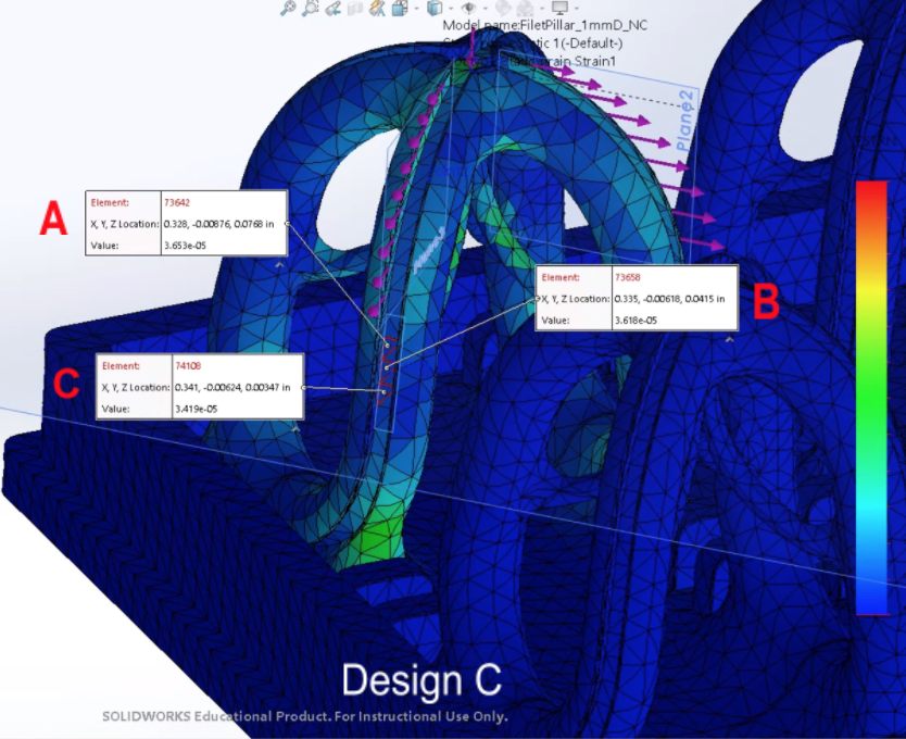
From the results over the past few days I have been working on editing the struts within the FBG structure. One idea we had was to spread the stress concentration by expanding the edge of the struts on the pillar by using the fillet tool in OnShape. I also adjusted the angle of the struts so they are not as perpendicular to the pillar wall, which will also help to eliminate the high stress concentration we found in our previous results. Below is the new edited design of the FBG structure:

(I will be referring to this edit as Design C)
As you can see from the original design (which was also edited last week to have deeper grooves and struts) I now have edited the angle and surface connection of the structs.
Then I conducted an FEA of the new design in order to compare them to the previously edited design in order to see if the edits to the structure are really optimizing the strain concentration in the wanted areas. Below are my compared results between Design B and Design C:
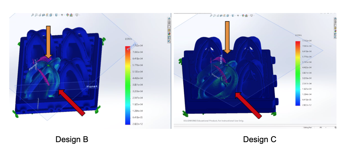
Within this comparison we want to focus on analyzing the strain where the normal force is being applied (orange arrow), and the the strain in the lower middle area of the pillar (red arrow) where the sensors will be attached.
Though through this comparison we could perhaps draw conclusions on the strain difference between the two designs my next step will be to quantitatively compare the difference in strain data by attaching sensors to the important areas (Red and yellow arrows) and reading the actual strain value in those areas to compare.
July 2 - July 5
FBG Structure Development!
For the rest of the week I will be concentrating on hopefully improving the FBG structure. Brainstorming with Sam we decided to add struts that attach to the center of the pillars in order to increase the strain in those areas. Below are the edits I made to the structure using OnShape in order to add the struts

(I will be referring to this edit as Design B)
Once the design was created I ran an FEA with the applied forces:

With these results Dr.Cutkosky, Sam and I discussed at our lab meeting how the area where the struts attach to the pillars (circled in red) has a really high stress concentration and would most likely break with the struts positioned at that angle. This can be seen as that area is highlighted in green from the FEA strain analysis.
For the following week I plan to edit the struts again and run more FEA with a different angle to hopefully find the most optimal way to increase the strain in the center of the pillars
June 29 - July 1
FEA and Editing!
This week I focused on both editing the FBG structure and running FEA to analyze the strain on the structure. From my results last week, Sam and I brainstormed ideas to create a more optimal structure. We decided to first make the grooves on the edge shallower, because the closer to the surface we have the sensors the more they can be strained. So, I edited the structure and then conducted the FEA and here are my results :

(I will be referring to this edit as Design A)
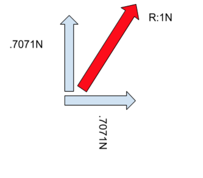
Though the results showed a slight dissemination of strain from the top to the rest of the structure there are definitely more edits we can make to the structure. Since the structure will also have multiple forces from different directions I also learned how to apply other forces in different direction on SolidWorks. We decided we wanted a resultant force of 1 Newton coming from the middle of two pillars (see figure below; the red arrow is the resultant force of 1 Newton from applying two vectors in adjacent directions of .7076 Newtons)
By adding these new directions (along with the normal force) I got the following results:
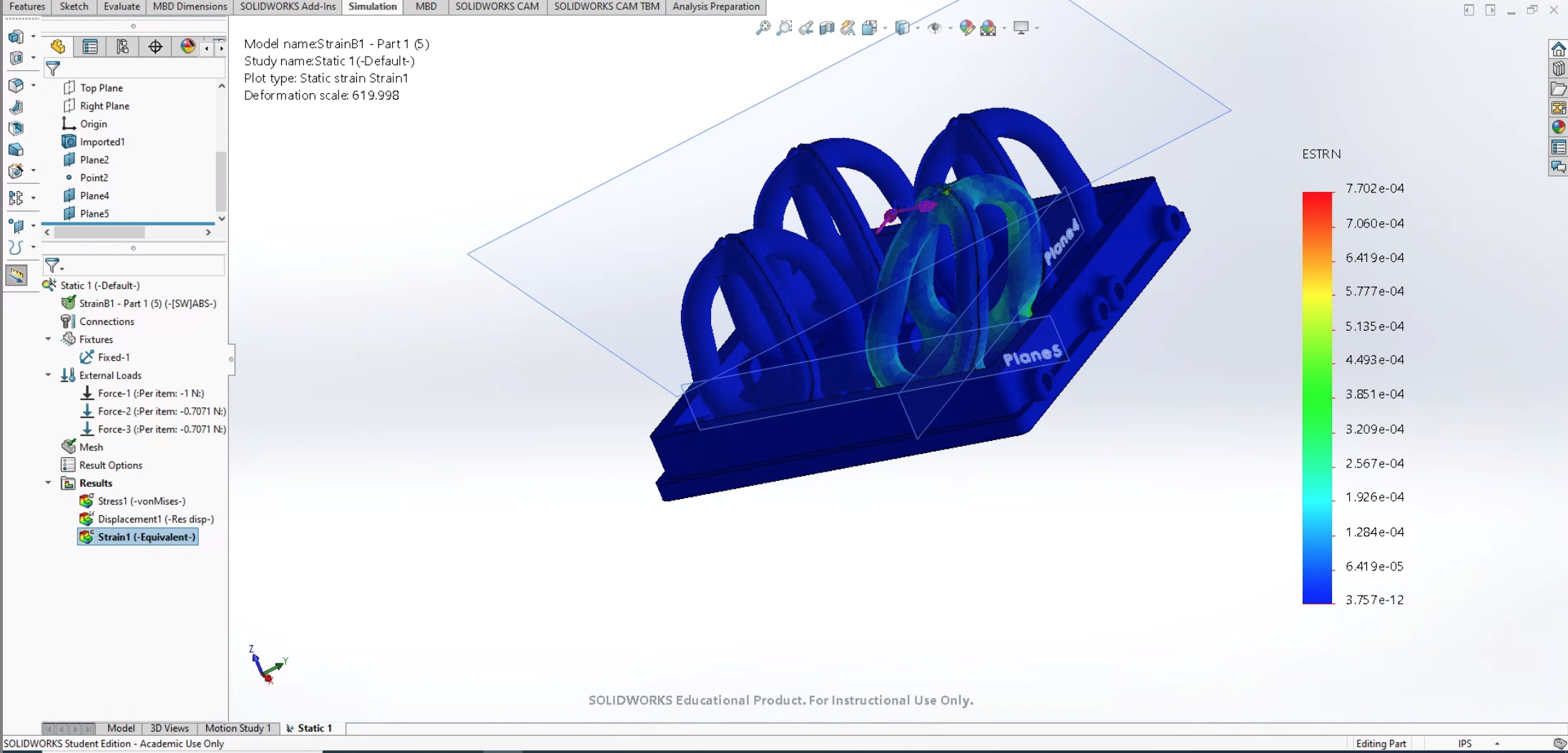
From these results we saw that we need to edit the structure near the center of the pillar in order to really concentrate the strain there. The green color is where there is more strain and we want that to appear closer to the middle of each pillar.
My goal for the coming days is to edit the current structure to increase the strain in the center of the pillars, as well as try to not have a-lot of strain concentrated in areas we don't need
June 25- June 28
Design Days!
As I continue my internship remotely I had to install two programs:
- SolidWorks
- Matlab
However, with a Mac SolidWorks was a challenge to install, so we ended up using a remote access desktop to in order for me to use SolidWorks. After everything was set up I was off ready to learn these programs.
Since SolidWorks is a CAD program I had to learn to design in CAD through Onshape. This was really exciting to learn and below are some simple designs I did to practice:
 |
 |
I spent a few days just practicing CAD in OnShape so that I could become decently proficient in it because I will need to make some edits to designs as I continue with the projects.
Projects:
FBG's:
Right now I have been focusing on the FBG project trying to understand what our goal is for this project and practicing running FEA in SolidWorks. This analysis allows me to apply forces to the FBG structure and run a simulation that shows the areas of strain within the structure when these forces are applied. The goals is to have strain more concentrated in the center of the pillars because this is where we will be putting the sensors. The figure below shows the current FBG structure we have and the red arrow shows where I will be applying a normal force of 1 Newton:

The goals is to apply many different types of forces at different angles but for this week I practiced just with normal forces in this direction. Below are the results to applying a normal force from the top:
From these results we saw that the strain is really concentrated at the top and not spread through the structure. Therefor my goal for the coming week is to edit the structure to allow for the concentration of strain to spread especially towards the center surface of the pillars.
June 22 - June 24
Kicking off the summer
Hi welcome to my summer research blog! I just started my SURF (Summer Undergraduate Research Fellowship) at Stanford on June 22, 2020! I am going to be participating virtually because of COVID-19 but am excited for the projects I will be working on.
Here are some things I have done the past few days and an overview on what I hope to be working on!
Meetings:
The first couple of days have been really engaging. I got to virtually meet Sam (graduate student) and Dr.Cutkosky, as well as some more lab members who work on medical devices. I also got to meet members of IFOS who we will be working with closely on one of the projects. I also went to my first meeting with the entire BDML Lab where everyone shared their goals for the summer. Here are mine!
 |
 |
Projects:
There will be a few projects I will have an opportunity to work on, a summary of the projects can be found here:
Tasks:
What I have done:
- Completed Onshape tutorials to learn CAD within this program
- Literature reviews of papers relevant to the four projects mentioned above
- Ran an FEA (Finite Element Analysis) through SolidWorks with Sam on the FBG structure design:
Goals for the coming week:
- Downloading a VM to run windows so I can work with SolidWorks on my mac
- Conduct FEA on some structures provided by Sam to better understand how to run FEA on a CAD model