Xitlali's 2024 Summer Blog
On this page... (hide)
1. WEEK 10 (August 26-30)
August 26
Today I had a SURI meeting. This is the last meeting for the summer. After the meeting, I went to CDR to catch the last part of the lab lunch. Here I heard about the lab backpacking trip. It was fun to hear about.
2. WEEK 9 (August 19-23)
August 15-21
These past few days I spent working on the SURI poster. On August 19 the SURIs had a poster review session with the lab to get feedback on our posters. After that session I kept editing the poster until I covered all the suggestions.
3. WEEK 8 (August 12-16)
August 15
Today I spent the day working on the poster for the SURI poster presentation. I was writing the content on the poster and formatting the poster.
August 14
Today I spent most of the day working on my poster. Specifically I was working on making some diagrams / schematics for the poster.
August 13
Today I tested the FTIR structure and Matlab script. After I was done testing and debugging some things I started to work on my poster for the SURI poster presentation.
August 12
Today I spent cleaning up the script making sure all the function and variable names were intuitive and formatted correctly. Additionally, I added descriptions for all the functions and added a description for the script as a whole. Tomorrow I plan to do some more testing of the script with some gecko tiles and start working on the poster for the SURI poster presentation at the end of this month.
4. WEEK 7 (August 5-9)
August 8
Today I kept working on the Matlab script. I added a few more functions and figured out how to take more images in a short amount of time without having to use a video feature. I also worked on making a function to turn all the images taken into grayscale, crop all the images taken to be just of the tiles, and used the analysis function I made yesterday to analyze the images. Tomorrow I plan to spend most of my time cleaning up the script, making sure it works and adding additional features.
August 6-7
These past two days I have been working on the script for the FTIR analysis. I made a function that calculates the percentage of the tile that is engaged when gripping to the glass plane. I plan to work on possibly taking a video on the tiles and then using the frames as images to do analysis on the images. And then figuring out the best way of doing the analysis on all the images. After I am done with that, I am planning on making the Matlab script user friendly and easy to read.
August 5
Today I spent most of the day figuring out how to take photos in intervals using the camera and Matlab. Additionally, I figured out how to save the images onto the current folder in Matlab. Tomorrow I plan to move on to the processing of the images.
5. WEEK 6 (July 29-August 2)
August 2
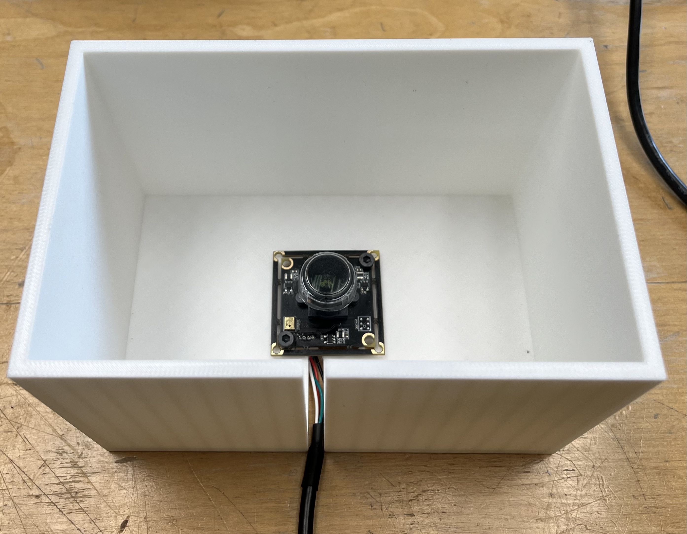
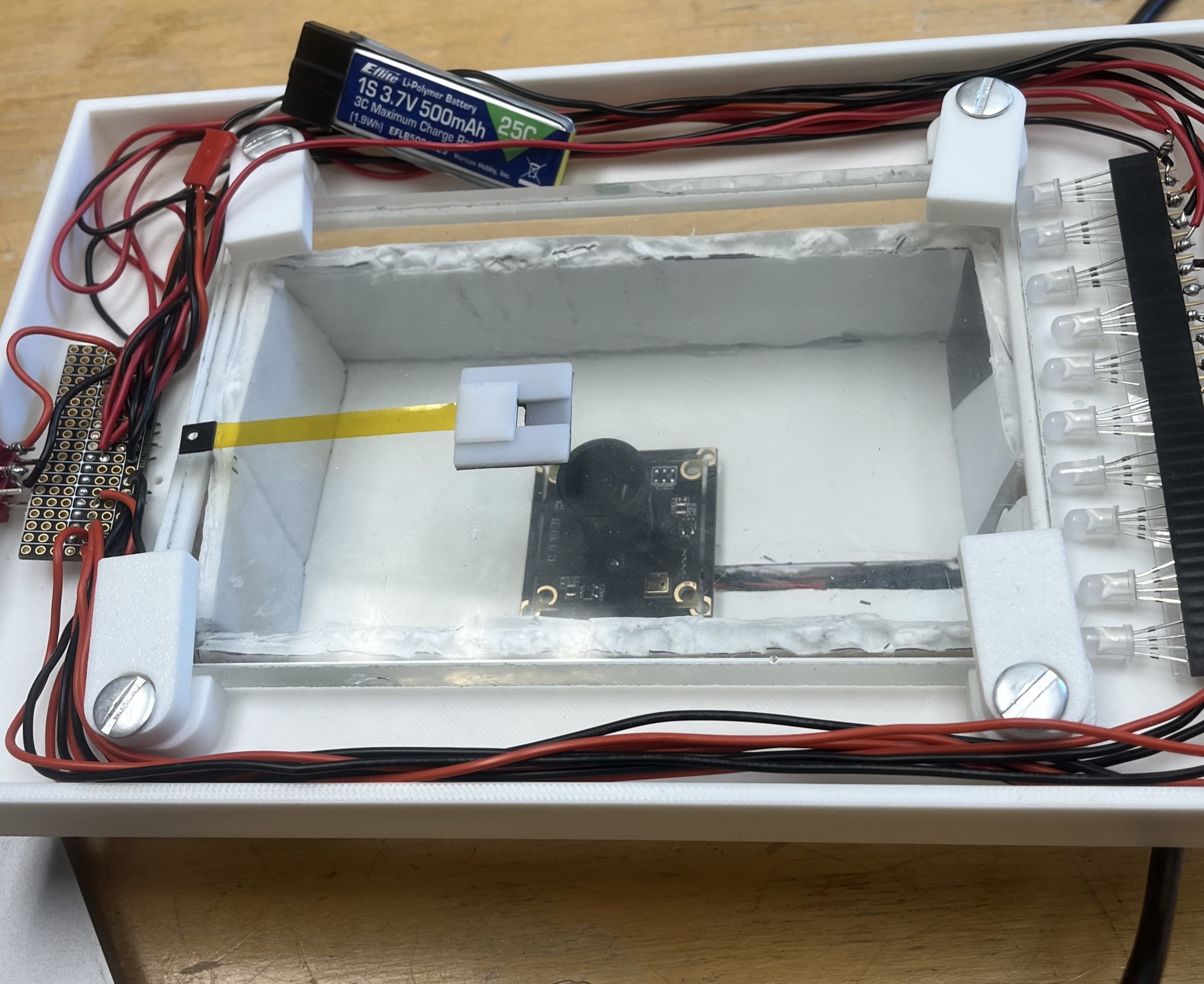
Today I continued to work on the structure where the camera sits. I tried putting on the heat set inserts, while doing so I realized I made the holes too small so when I tried to put the heat insert in it would get clogged with plastic. However, after a while of modifying the structure I was finally able to put the heat set inserts in. This took me a while since I initially put the heat set inserts slightly in the wrong place. I was able to fix the heat set inserts so that the camera sits in the right place. After I finished putting the camera in I started to work on the pseudo code to take the photos and analyze them. Next week I plan to work on the script on Matlab.
August 1
Today I picked up the 3D printed base for the camera. I tried aligning everything I needed to in order to secure the camera, but it did not align. So I tried removing some material so the tolerance was bigger but I accidentally removed material in the incorrect place. Tomorrow I plan to go back to the PRL and remove the material in the right spot this time. After, I realized that I messed up removing the material, I switched over to playing around with the Matlab Script that EmJ provided me. After playing around for a while and looking at Matlab documentation I have a better idea of what the script is doing and how it is doing it. Tomorrow I plan to write a pseudo code of how I can improve the current script and tailor it to the project's needs better.
July 31
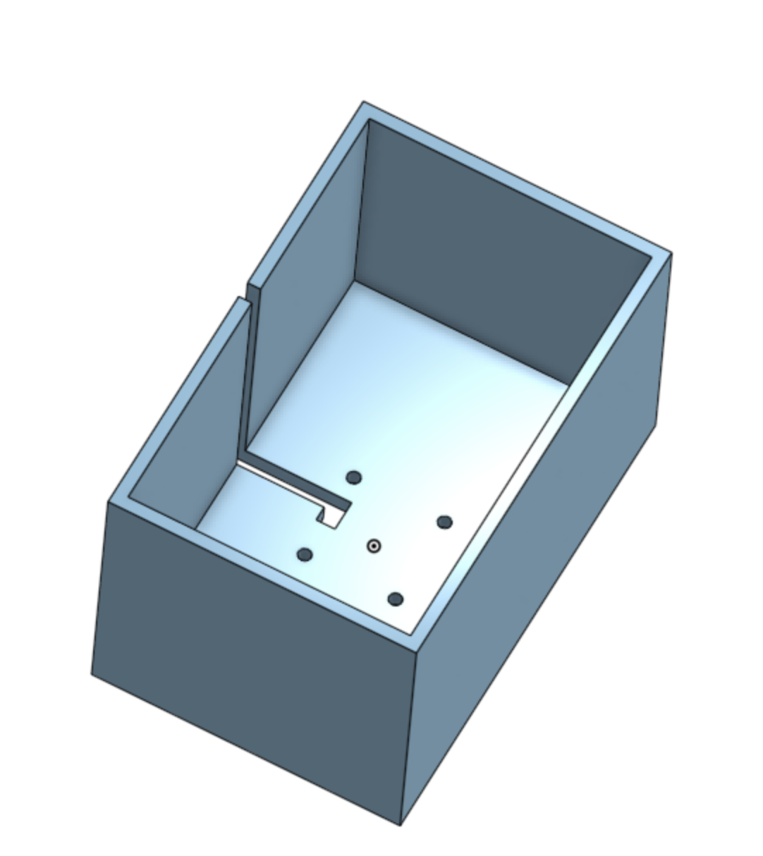
Today, I finished CADing the base where the camera will sit. I went to the PRL to get it 3D printed. Additionally, I briefly looked at the FTIR_Interpretation code that EmJ sent me. At first glance I don’t really know what's going on. Tomorrow I hope to look at the Matlab code in better detail and hopefully start writing some pseudo code.
July 30
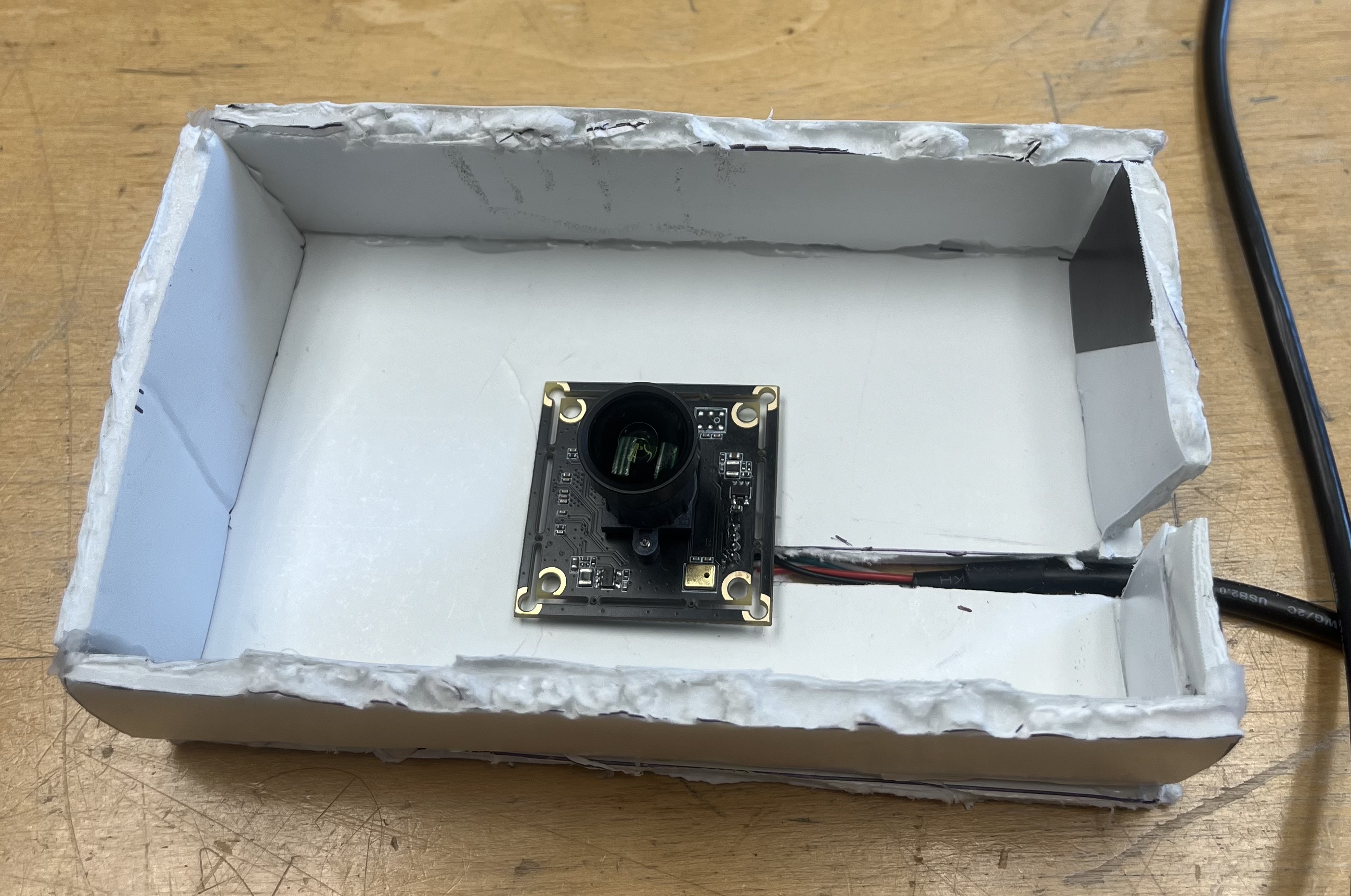
Today I played around a little bit with the camera. I also made a rough prototype with foam core for the base for the camera. After I made the rough prototype I realized that the base’s height was too short, and so the entire glass plane was not visible, through the camera. After making the rough prototype and testing it out with the camera, I started making the CAD for the base. Tomorrow I plan to finish up the CAD and get it 3D printed.
July 29
Today I spent most of the day trying to get the camera to show up on my computer using a USB. Tomorrow I plan to play around with the camera and Matlab.
6. WEEK 5 (July 22-26)
July 26
Today I attended the lab meeting. It was cool to learn about what Hojung was working on during the duration of his PhD. It was also interesting to hear the feedback during his practice defense. I also talked to EmJ to see what the next step is for the FTIR and it is to add a camera to quantify the contact area of the gecko tiles on the surface they are ‘sticking’ to. For the rest of the day I reviewed the papers that I read on July 1st. Additionally, I added the webcam add-on for Matlab and imported the template code and old script for interpreting FTIR images that EmJ sent to me.
July 25
Today I just reviewed the gecko adhesive papers that a read a few weeks ago.
July 24
Today I finished assembling the FTIR set up. After I completed that, I started to work on the presentation for the SURI meeting on Monday. Tomorrow I plan to review the Gecko Adhesive papers that I read a few weeks ago.
July 23
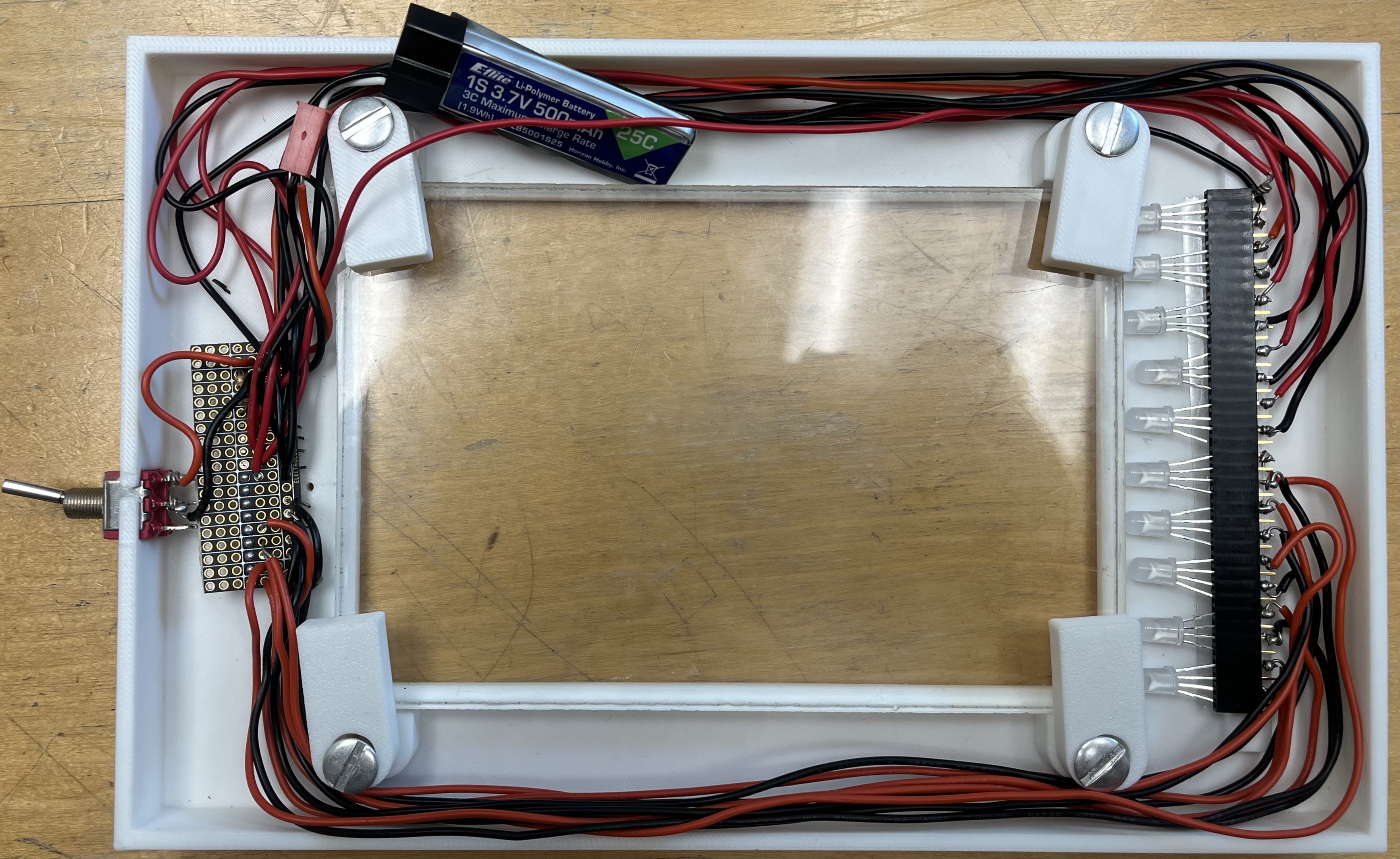
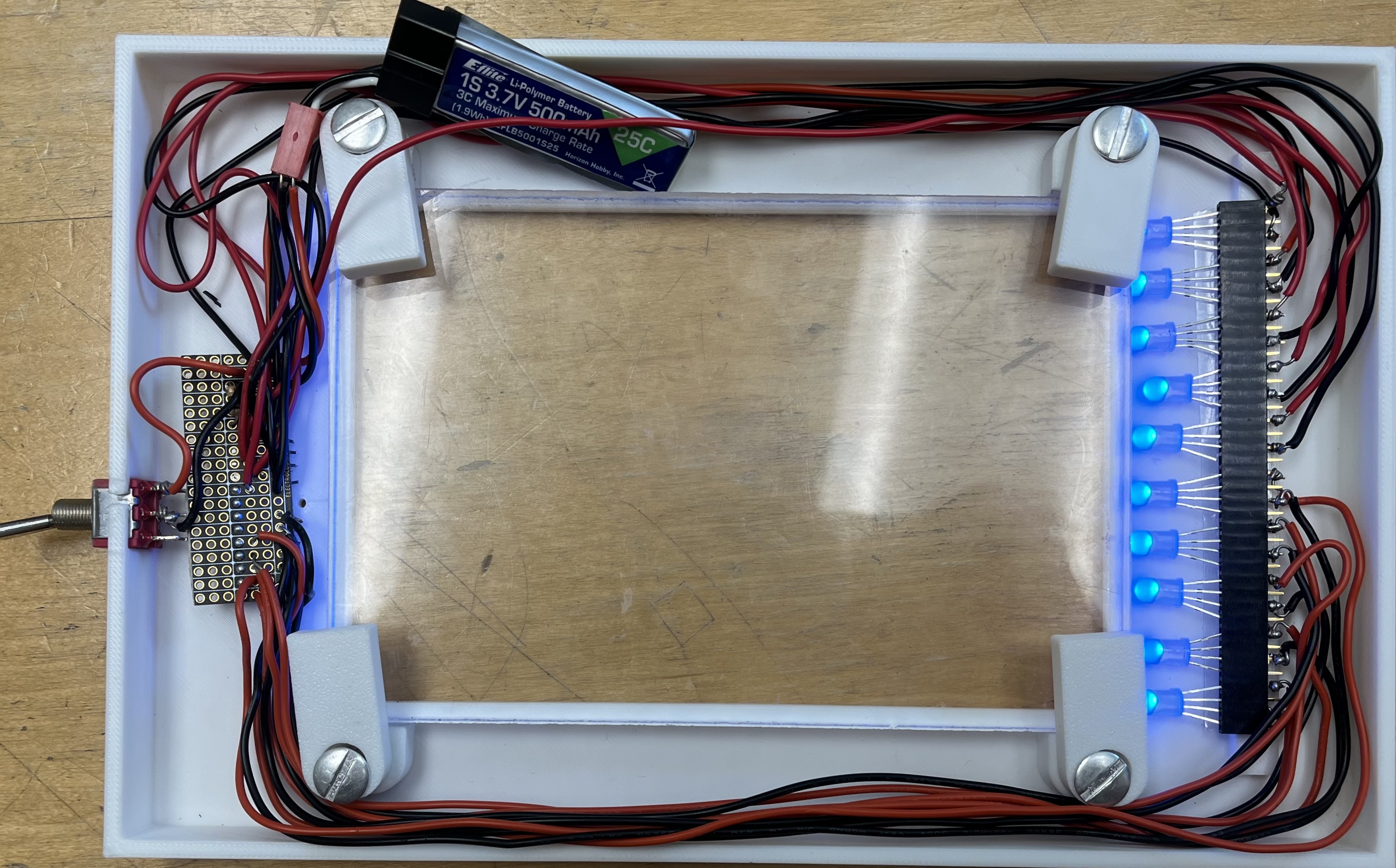
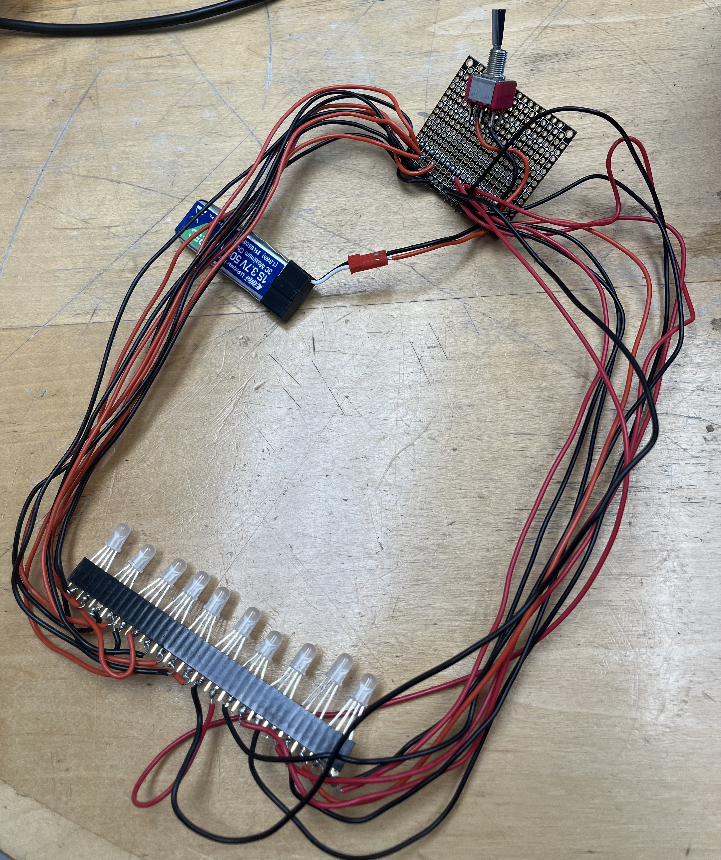
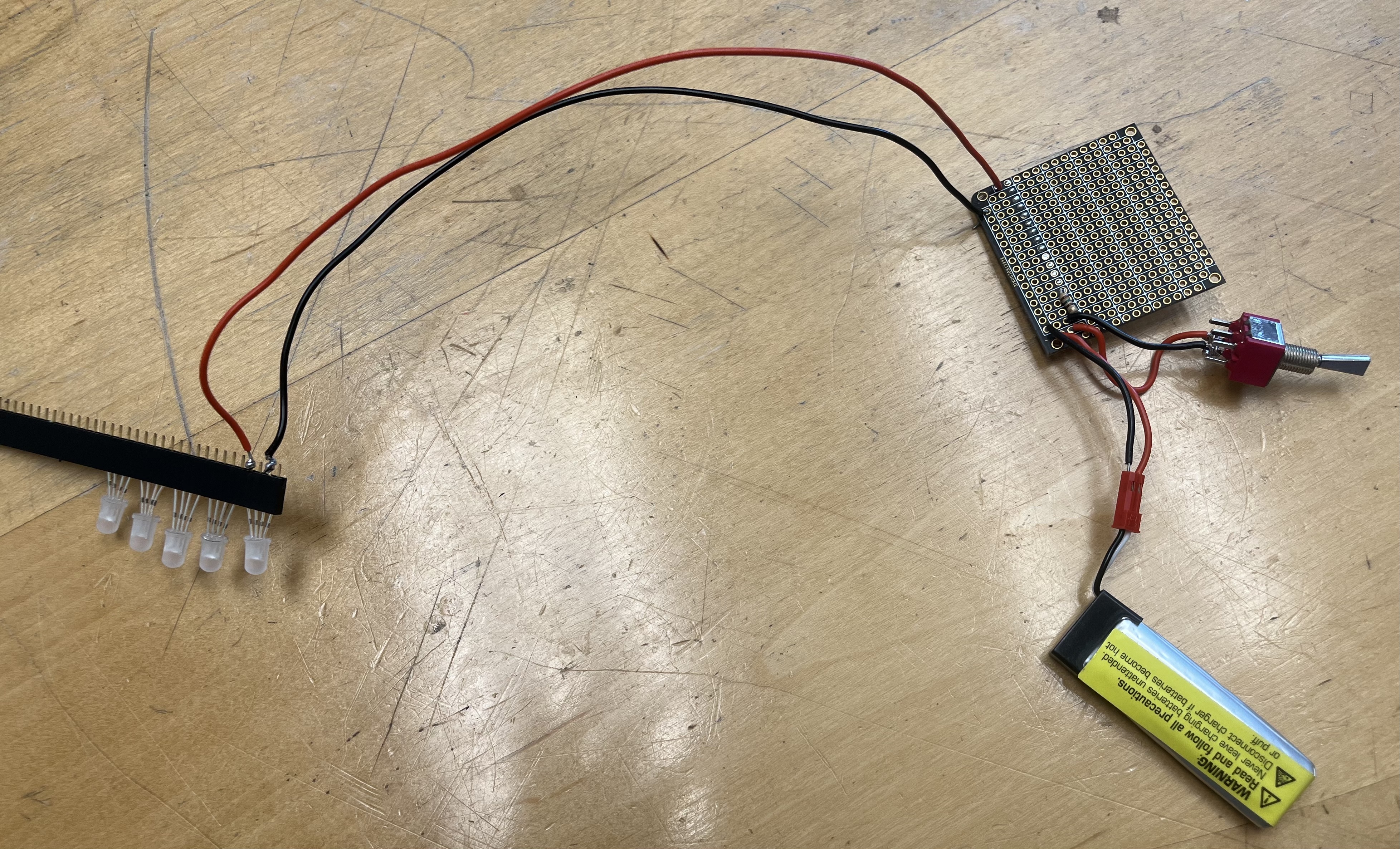
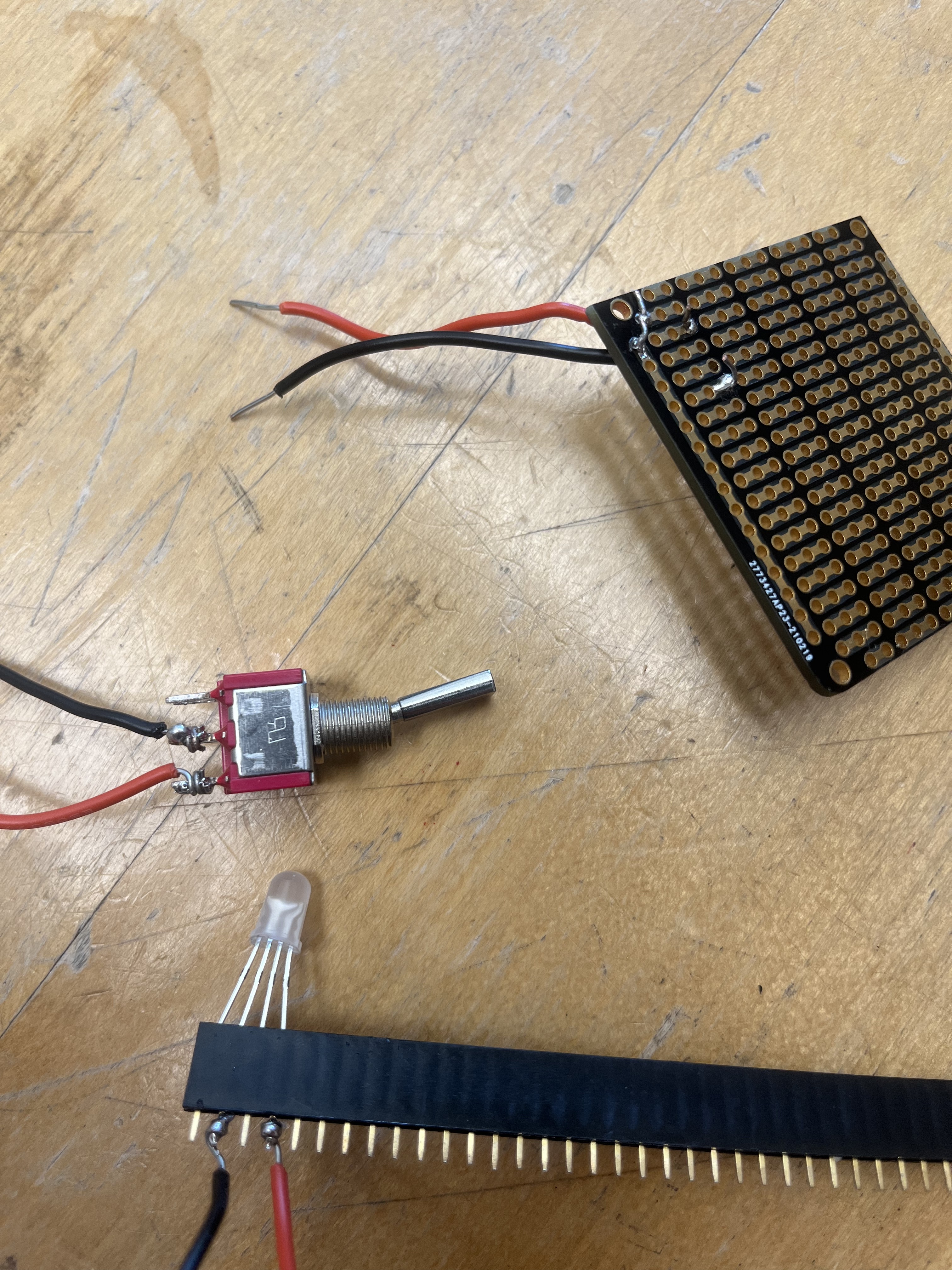
Today I spent the day soldering what was left to solder. I was able to make all the LED lights light up and off when the switch toggles on and off. Tomorrow I plan to assemble the FTIR.
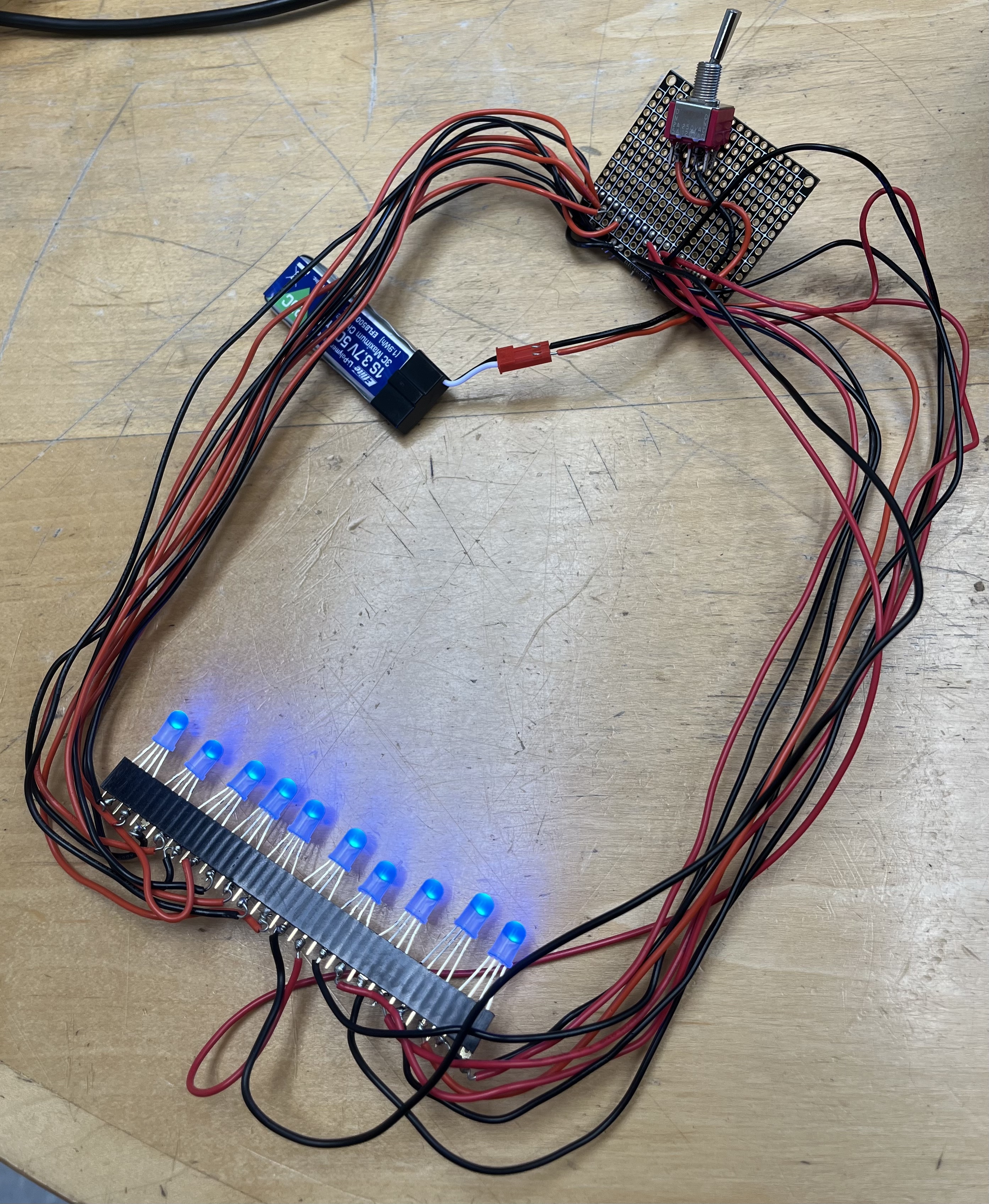
July 22
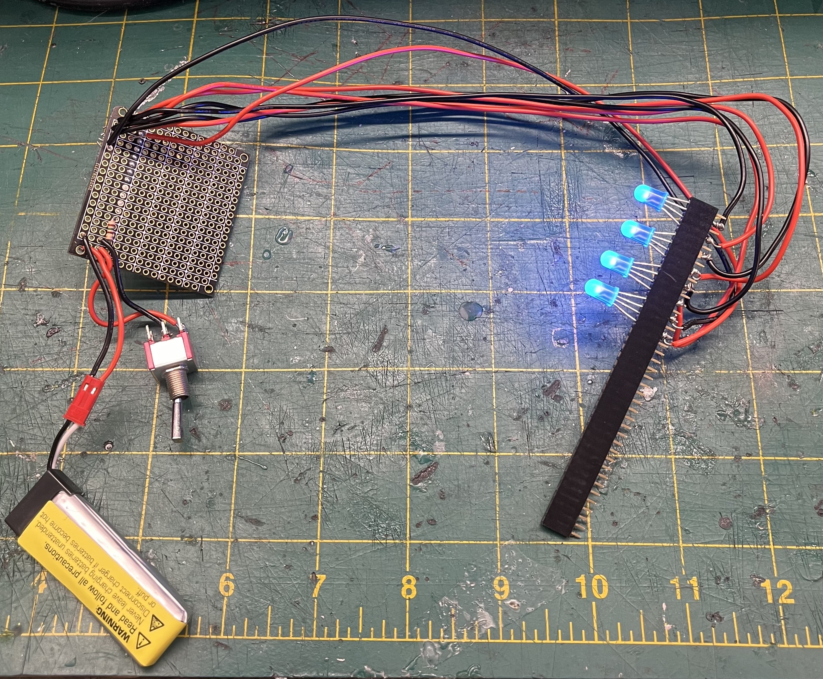
Today I finished cutting the RGB LED lights to size. Additionally, before lunch I started to work on my slideshow for when I have to present during the SURI meeting on Monday. Then after lunch I continued to work on soldering all the wires to the stripboard and to the female header pins. I was only able to solder so that four of the LEDs light up. Tomorrow I hope to finish soldering and start assembling the FTIR and troubleshoot if necessary.
7. WEEK 4 (July 15-19)
July 19
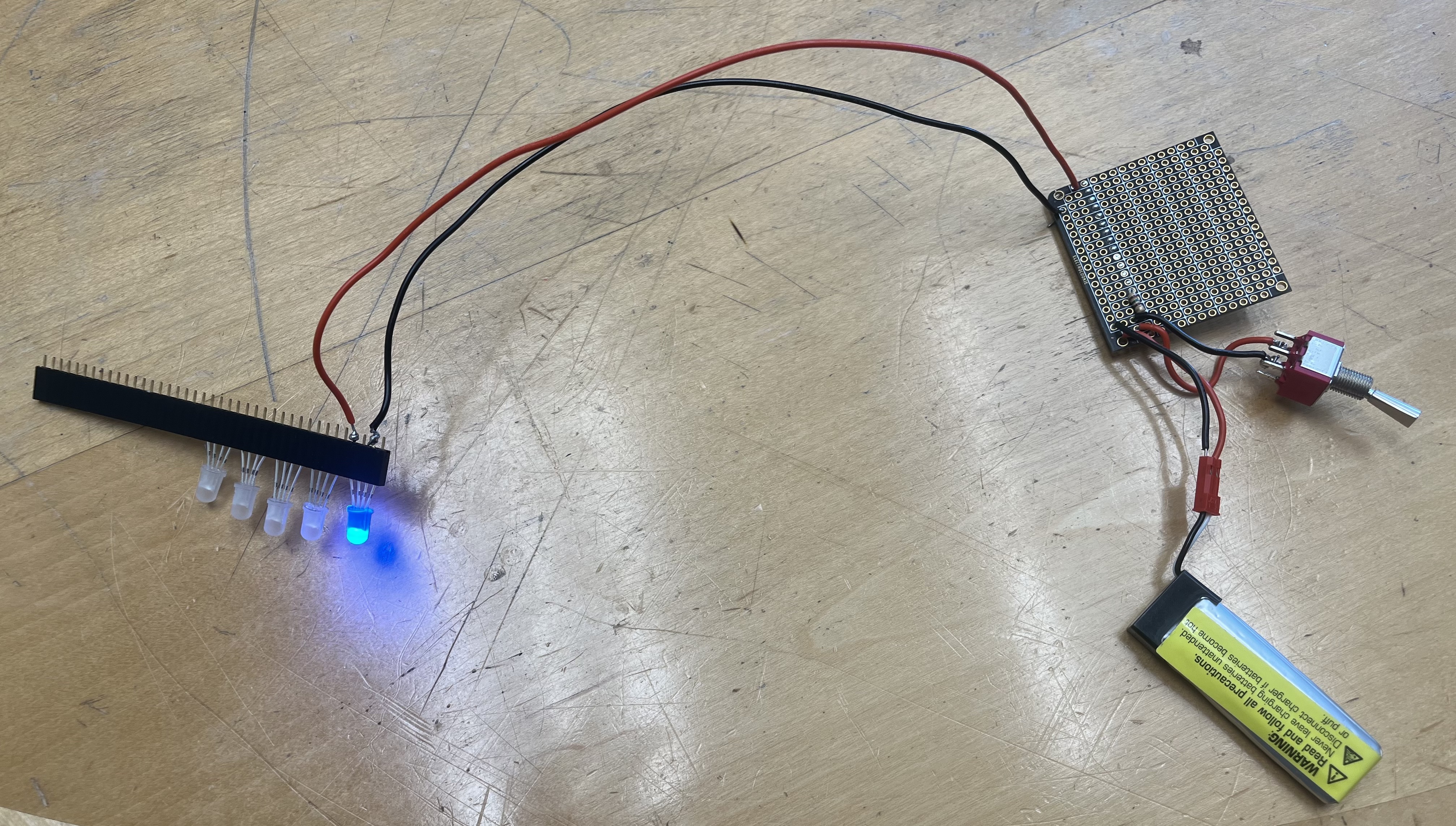
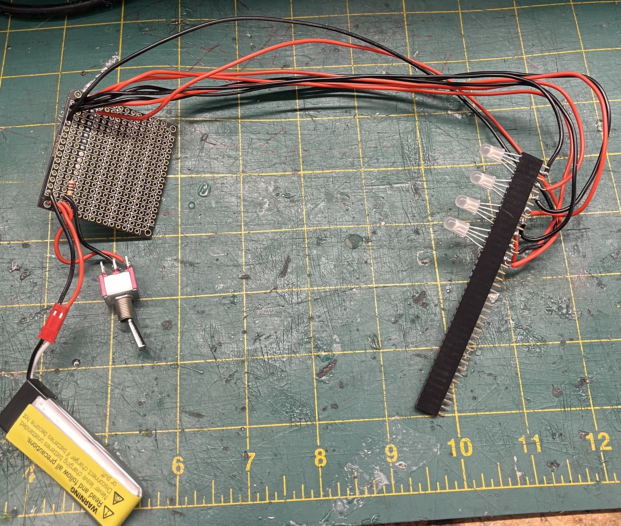
Today the lab had its weekly meeting. This meeting we learned what Julia was working on. I thought the drone perching was very interesting. After the lab meeting everyone went back to the lab and started cleaning up. After cleaning up and lunch I worked on some more soldering. I soldered to test one LED light first to see if the switch and everything worked. When I tested the light it did work. So for the rest of the day I cut a few more LEDs to length. I didn’t finish cutting all that I needed to, so I’ll pick this up on Monday along with soldering the rest of the components.
July 18
Today I finished up my schematic on Fritzing. Then after lunch I worked on a short presentation with Abi to introduce the lab to Fritzing during tomorrow's lab meeting. Finally, after that I started soldering the components. However, while soldering I realized that I would not be able to fully assemble the FTIR with the current structure. So after soldering some parts I went to the PRL to modify the structure.
July 17
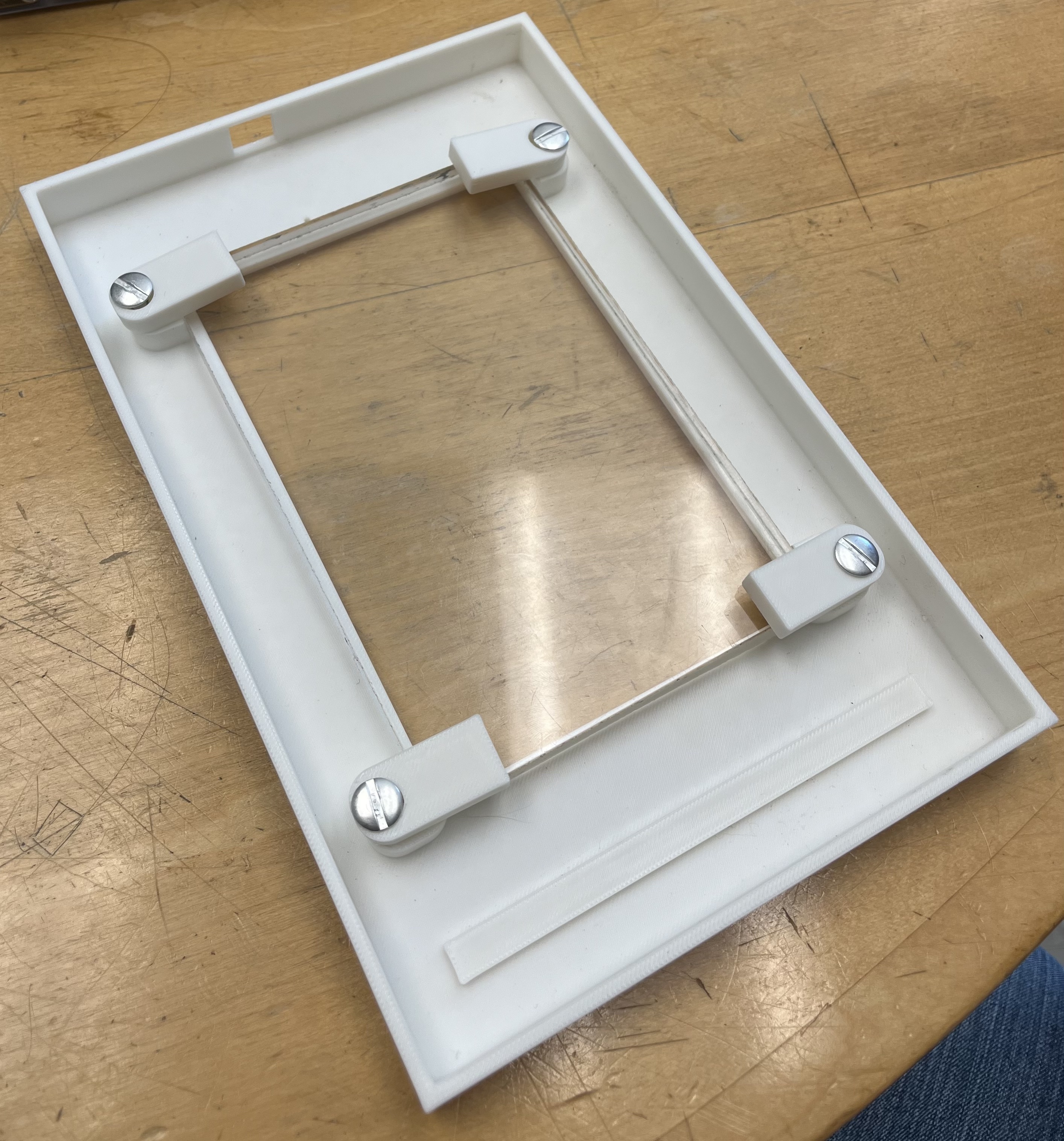
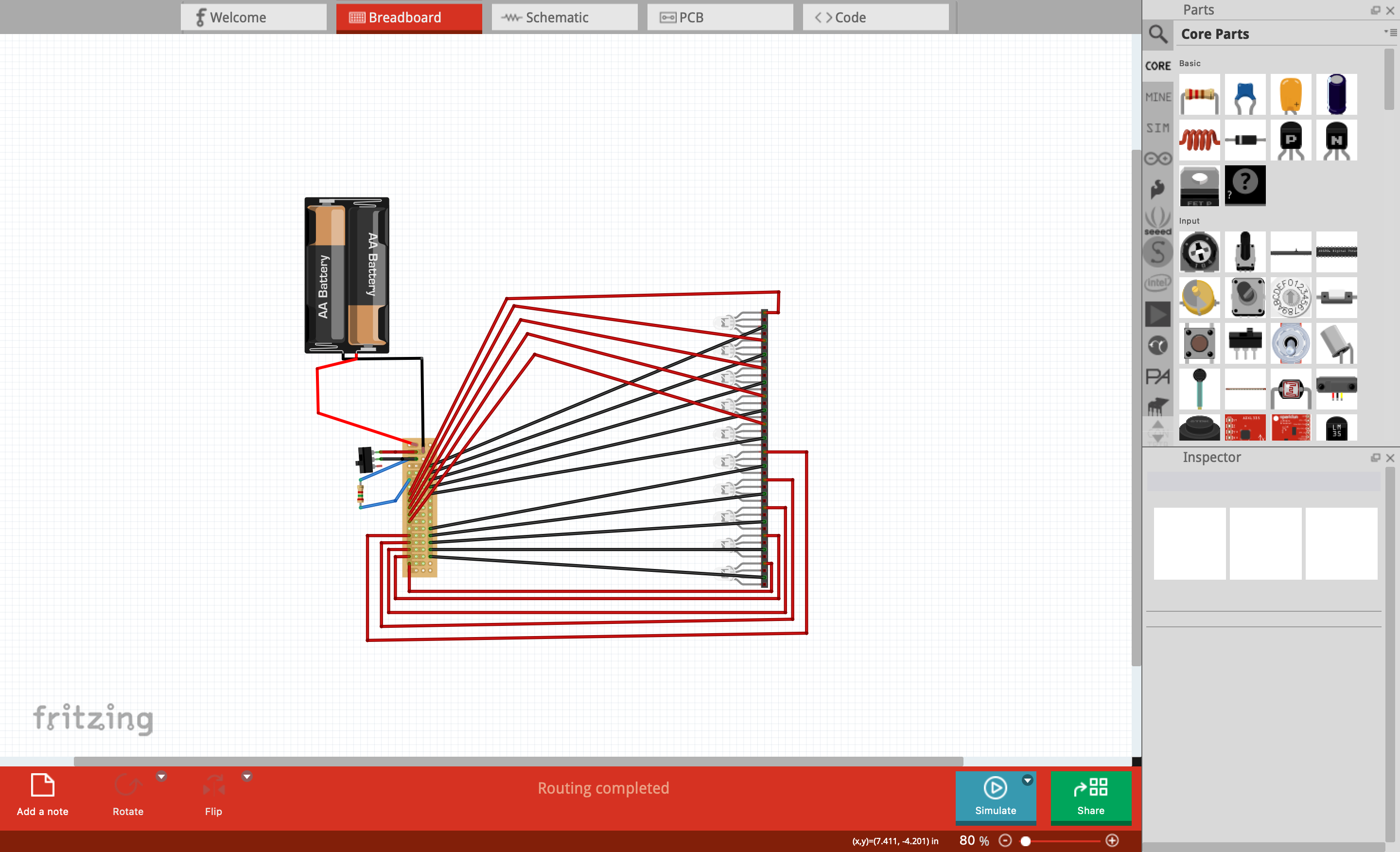
Today, I picked up the 3D printed structure from the PRL. When I got back to the lab I tried inserting the glass plane in the center, however, it didn’t fit since there was not enough tolerance for the corners where the glass plane was supposed to go. So after lunch I went to file down the corners so that the glass plane fit. After that I assembled the glass plane to the structure. Today I was also working on Fritzing to make a schematic of the stripboard, battery, and LEDs. However, I spent most of the day with that since I was trying to simulate the circuit. Later today Dr. Cutkosky mentioned that Fritzing is mostly used for making schematics. So I worked on that for the rest of the day. Tomorrow I am going to finish the schematic on Fritzing and then I hope to start soldering the wires and everything together.
July 16
Today I started using Fritzing (see Private.Fritzing@BDML) to draw up a schematic of the soldering I’m going to have to do in the near future. Today I also got the structure for the FTIR setup 3D printing. Tomorrow I am going to pick it up and do a test set up with the glass and the other components. I also plan to finish the schematic so I can solder on Wednesday or Thursday.
July 15
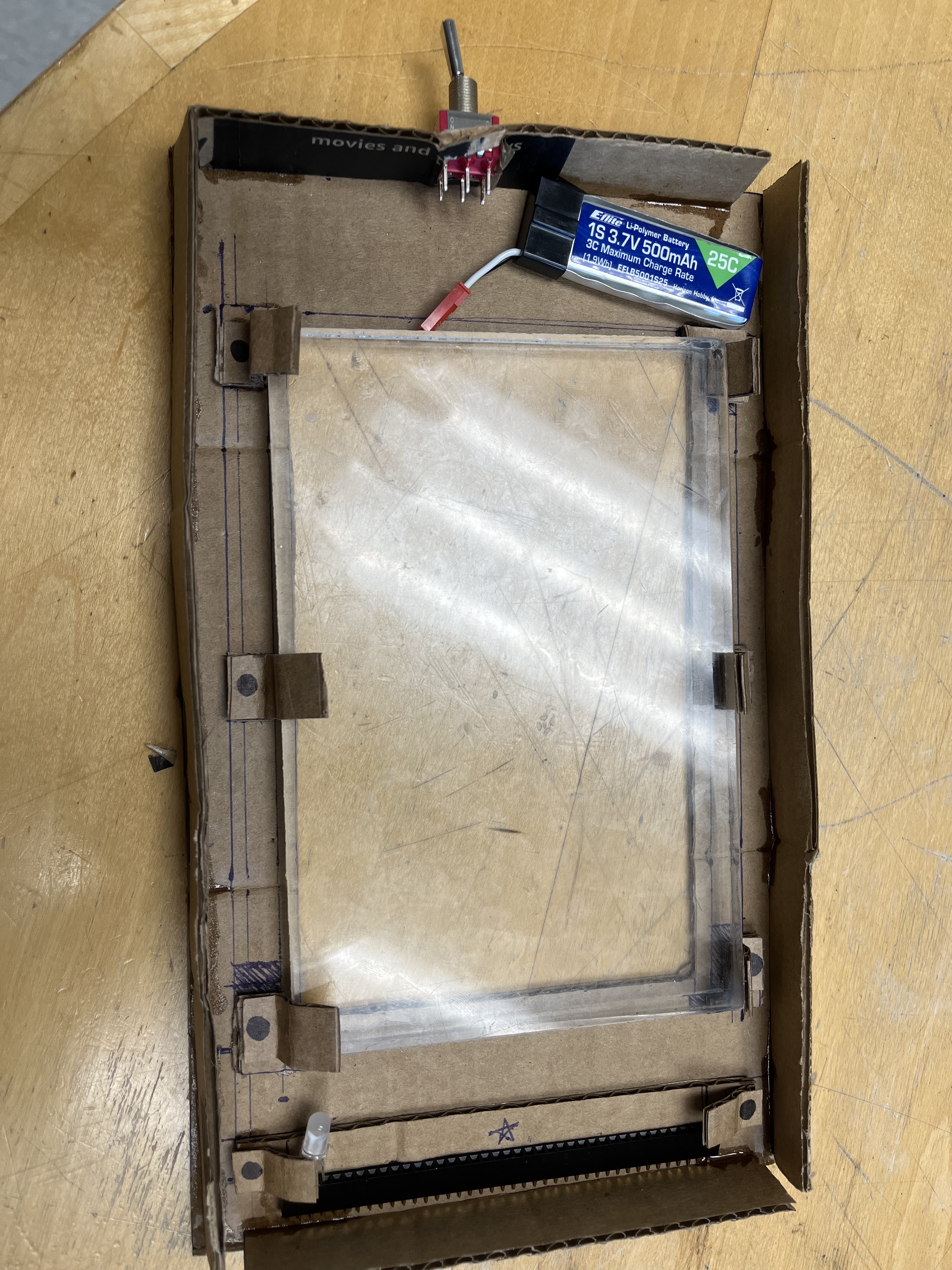
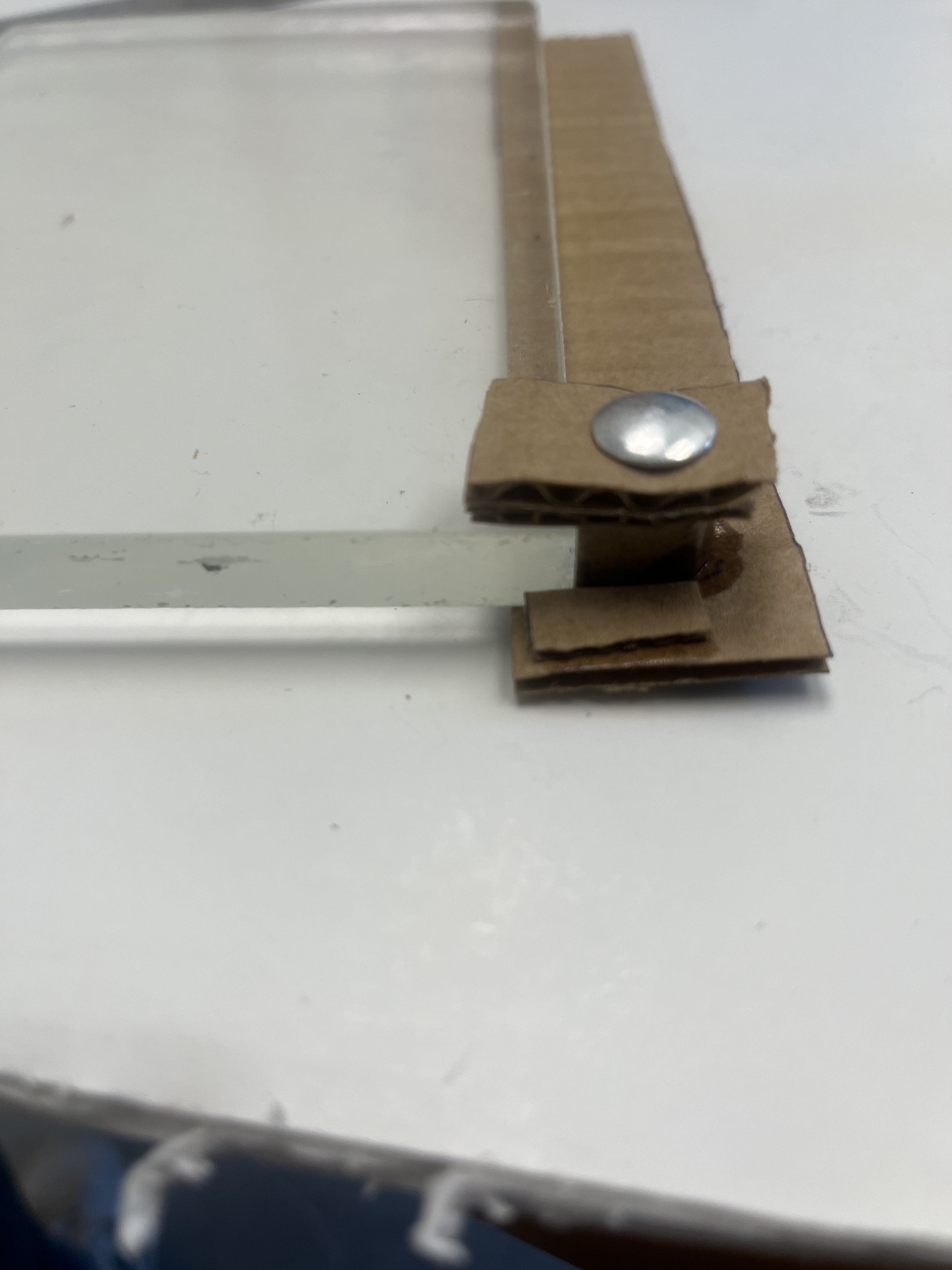
Today I finished up making my cardboard prototype. While I was finishing up, Dr. Cutkosky helped me figure out how to fasten the glass to the structure. He suggested using post screws, that was very helpful since I was planning on using heat set inserts and then using screws. So after Dr. Cutkosky’s suggestions I finished up my prototype and then made a quick drawing of the new fastening mechanism. I was having a hard time visualizing my drawing so I made a small prototype of the fastening mechanism. After I figured out the mechanism I CADed it. After looking at the CAD I noticed that it looks similar to the CAD I did last week (July 10). However, this time this CAD is more finalized with the final dimensions and now I know what type of fasteners I will be using. Tomorrow I plan to start getting the structure 3D printed and while it's printing to work on the soldering diagram.
8. WEEK 3 (July 8-12)
July 12
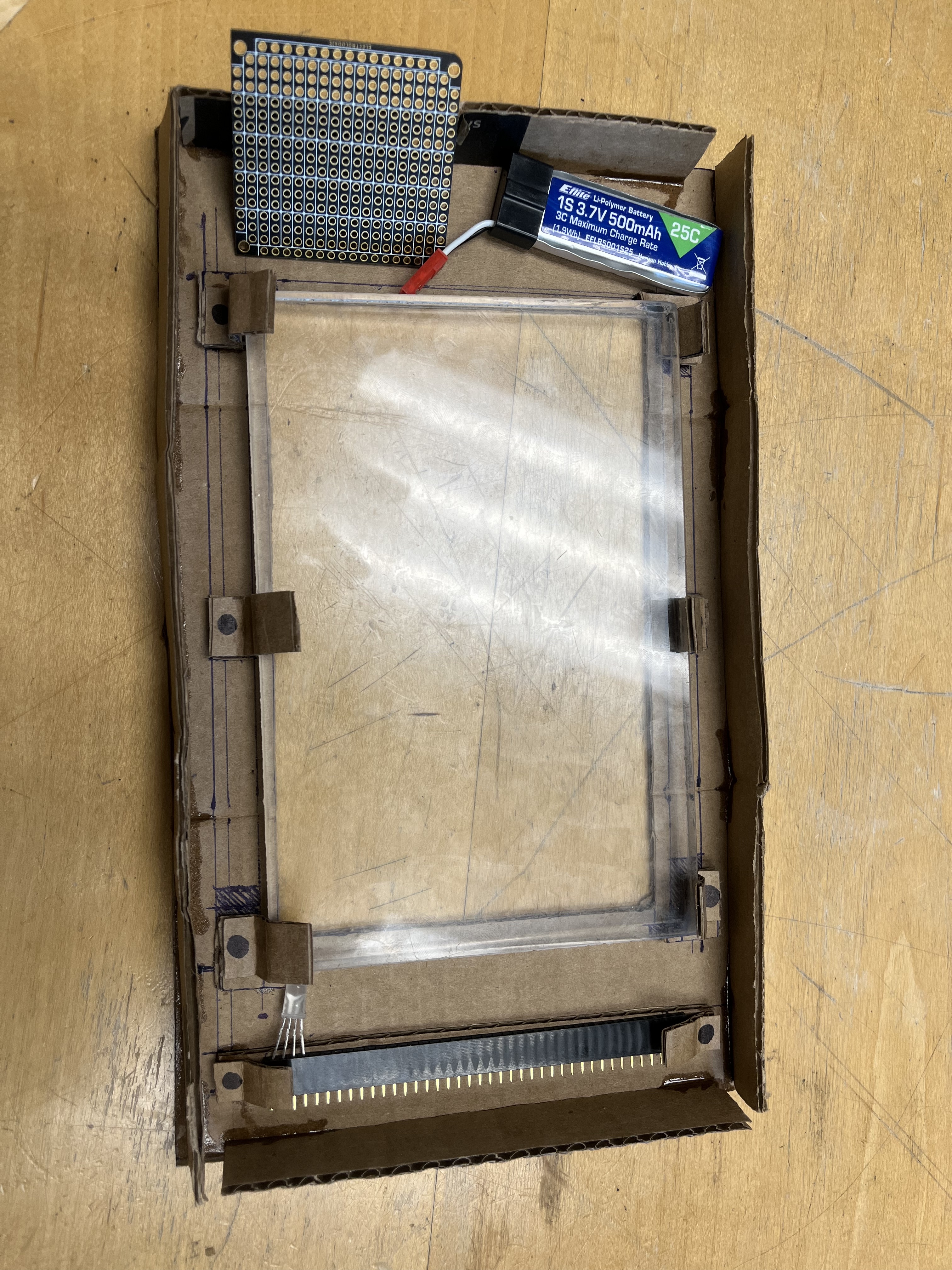
Today we had a lab meeting. There EmJ talked more about the gecko grippers and the challenges of using them in Space. After that, I was looking at the different fasteners the lab had and tried to briefly look for heat set inserts for when I eventually 3D print the structure. For the rest of the day I was working on making a rough prototype of the structure out of cardboard. I didn’t finish but I got the majority of the components. I have to make the walls of the structure and figure out how to fasten the glass panel to the structure. Towards the end of the day the lab went to the robotics happy hour at the robotics center. It was nice to mingle and talk to other SURI’s from the other labs.
July 11
Today I spent most of today reCADing my design. While reCADing my design, I learned more about how to use more of Onshape, specially making different part studios for each part in my design and assembling it in an assembly file and how to make a part in context to the assembly. In this new CAD I added some new elements such as a stop so the glass plane doesn’t move side to side. Additionally, I added more details in my CAD to accurately represent the final structure with all the components of the FTIR. My previous CAD had rough shapes and dimensions of the elements. Since all the dimensions are mostly finalized, I plan on making a rough prototype tomorrow with cardboard and foam core. I plan to follow the CAD exactly and see if there are any flaws. By doing this I also plan to finalize how I will fix the glass plane to the structure. I have an idea, but don’t want to CAD it yet in case it doesn’t work. Hopefully I’ll figure out the fastening system tomorrow.
July 10
Today I spent most of my time CADing my other designs. While CADing I realized some modifications to my design that I could make that were similar to my first design. After I CADed up my design I talked to EmJ to see if I missed any details in my design. She mentioned adding another hard stop on the sides of the glass so it doesn’t move side to side and to do the same thing for the LEDs. Tomorrow I plan to make a finalized CAD of the structure since the CAD I did today was just for me to get my idea on ‘paper’. Today I also learned how to cast, in the casting corner. I don’t think I’ll do a lot of casting during the summer but it was nice to learn since I haven’t casted silicone before.
July 9
Today I mostly spent CADing the design I worked on yesterday. When CADing I was also thinking through what other constraints there were that I didn’t think of when I was drawing out my idea. This made the CADing a bit longer than I thought it would. Additionally, I am unfamiliar with Onshape so that also contributed to CADing taking a while. However, I made some progress, I finished the CAD so that I could visualize my idea. After I was done CADing, I drew out another idea for the structure for the FTIR. I started CADing this idea today also, and I plan to finish it tomorrow. After I finish CADing my second idea I plan to make a finalized version. With this version I plan to CAD it more detailed (adding fasteners and other things that are not included in my current CAD files) so then I can start building it.
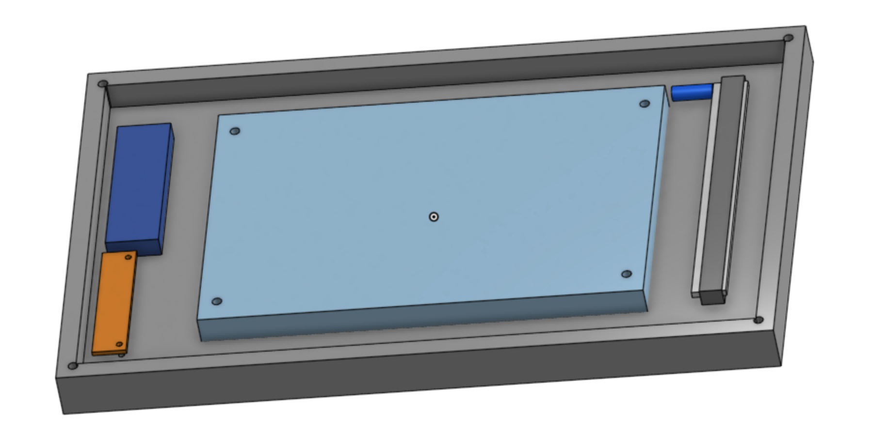
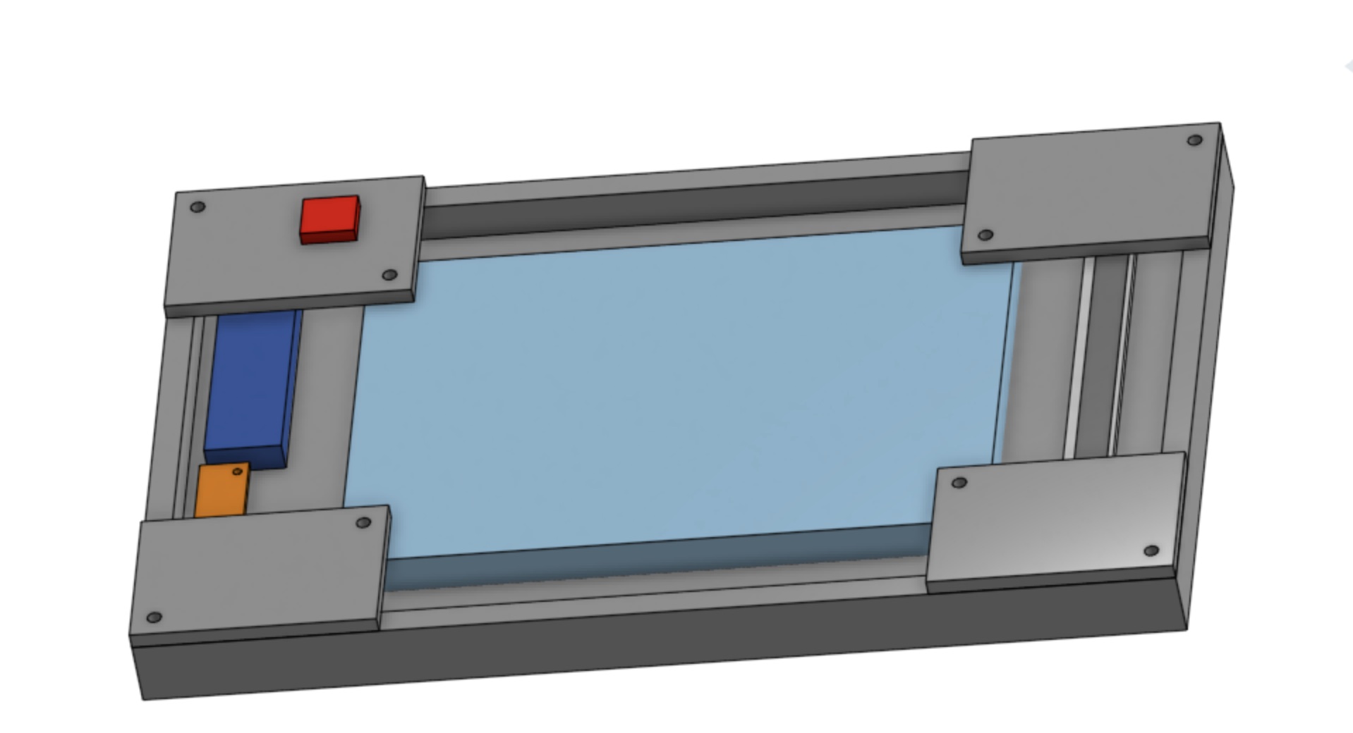
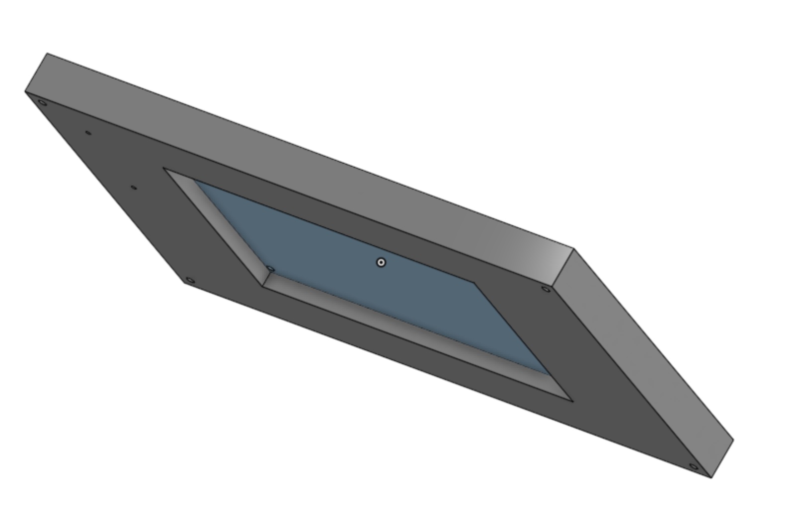
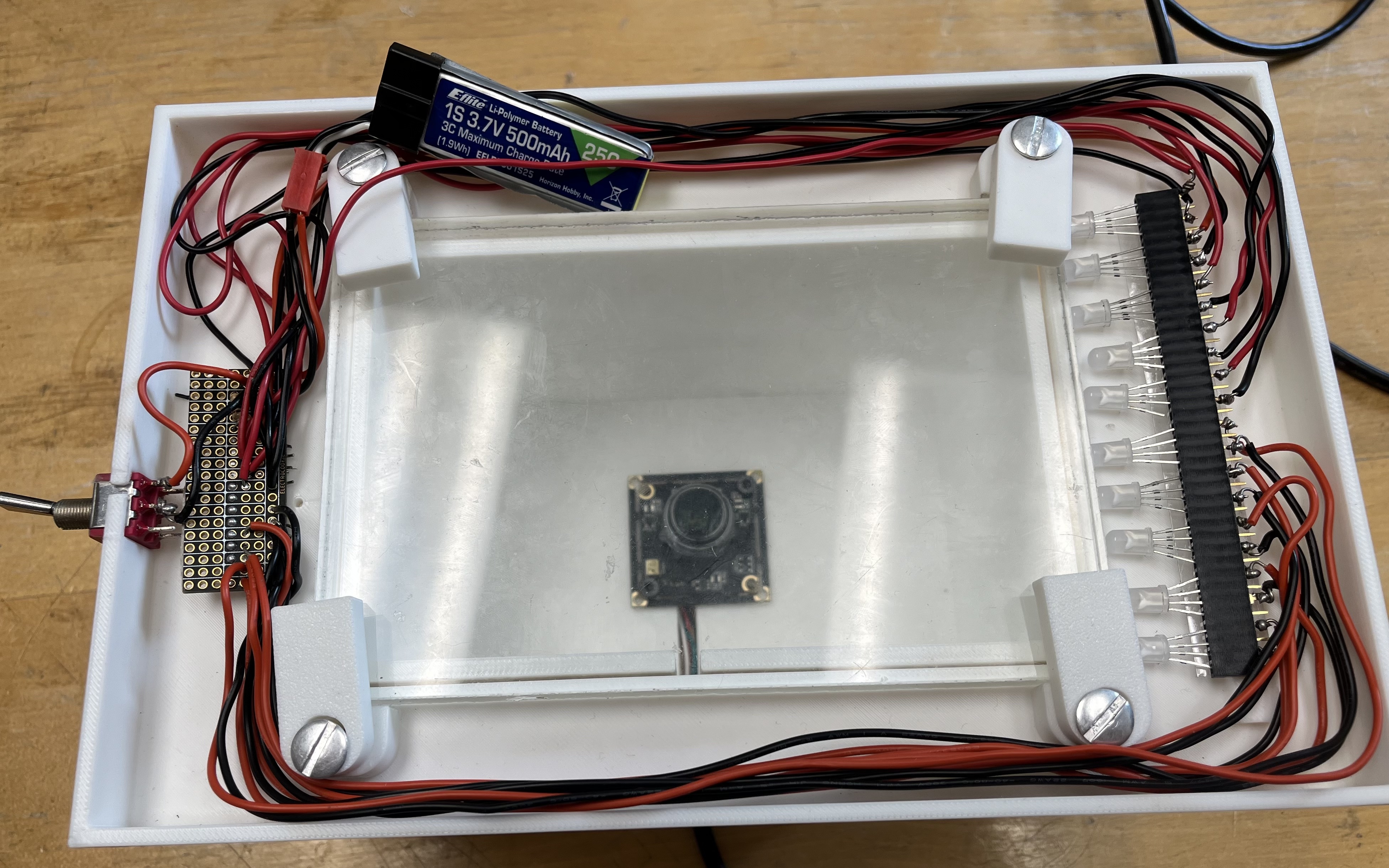
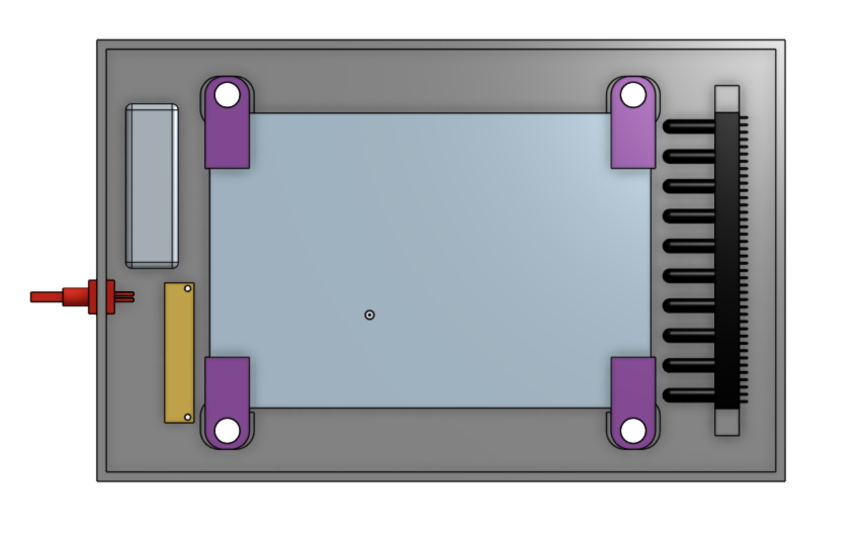
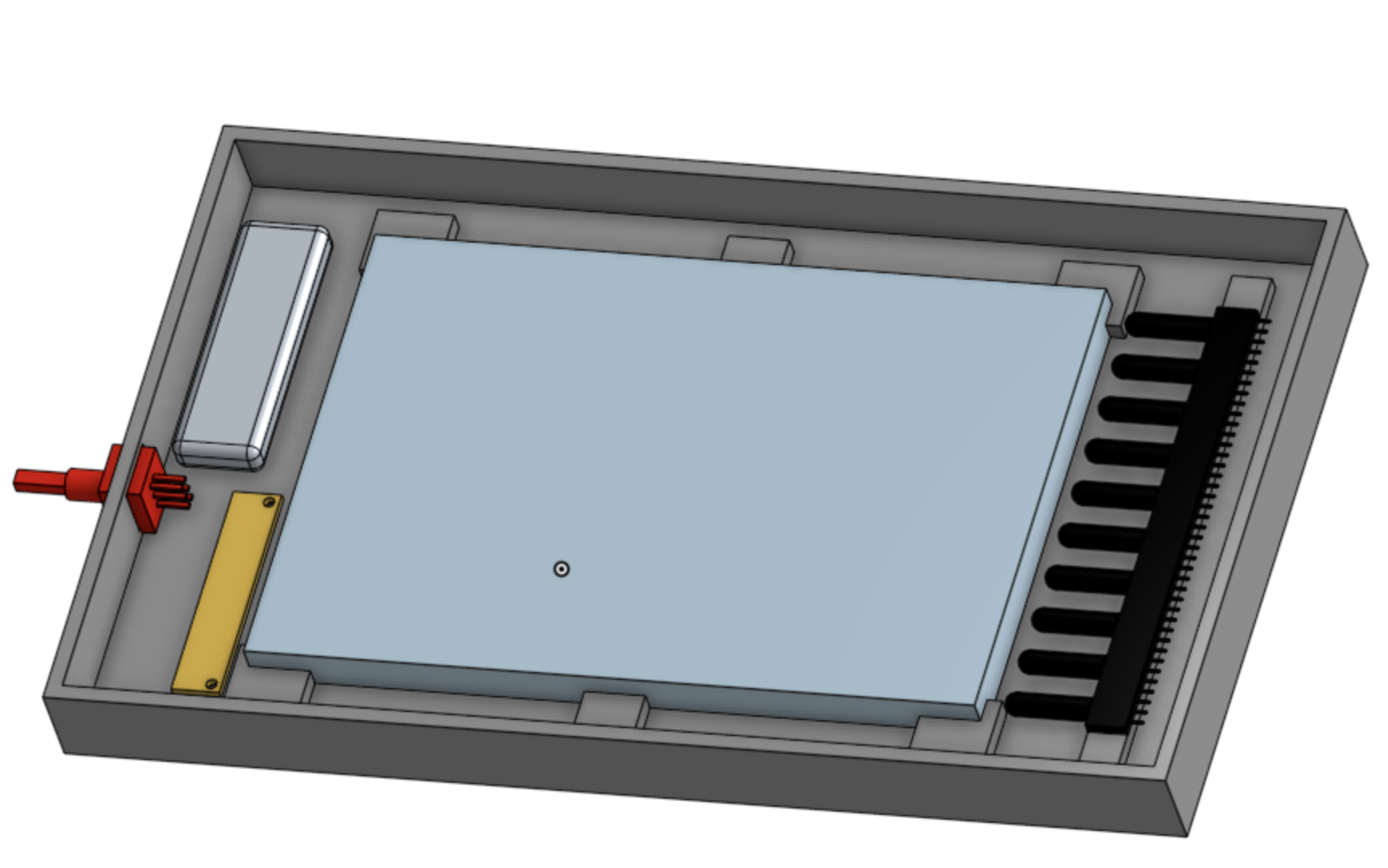
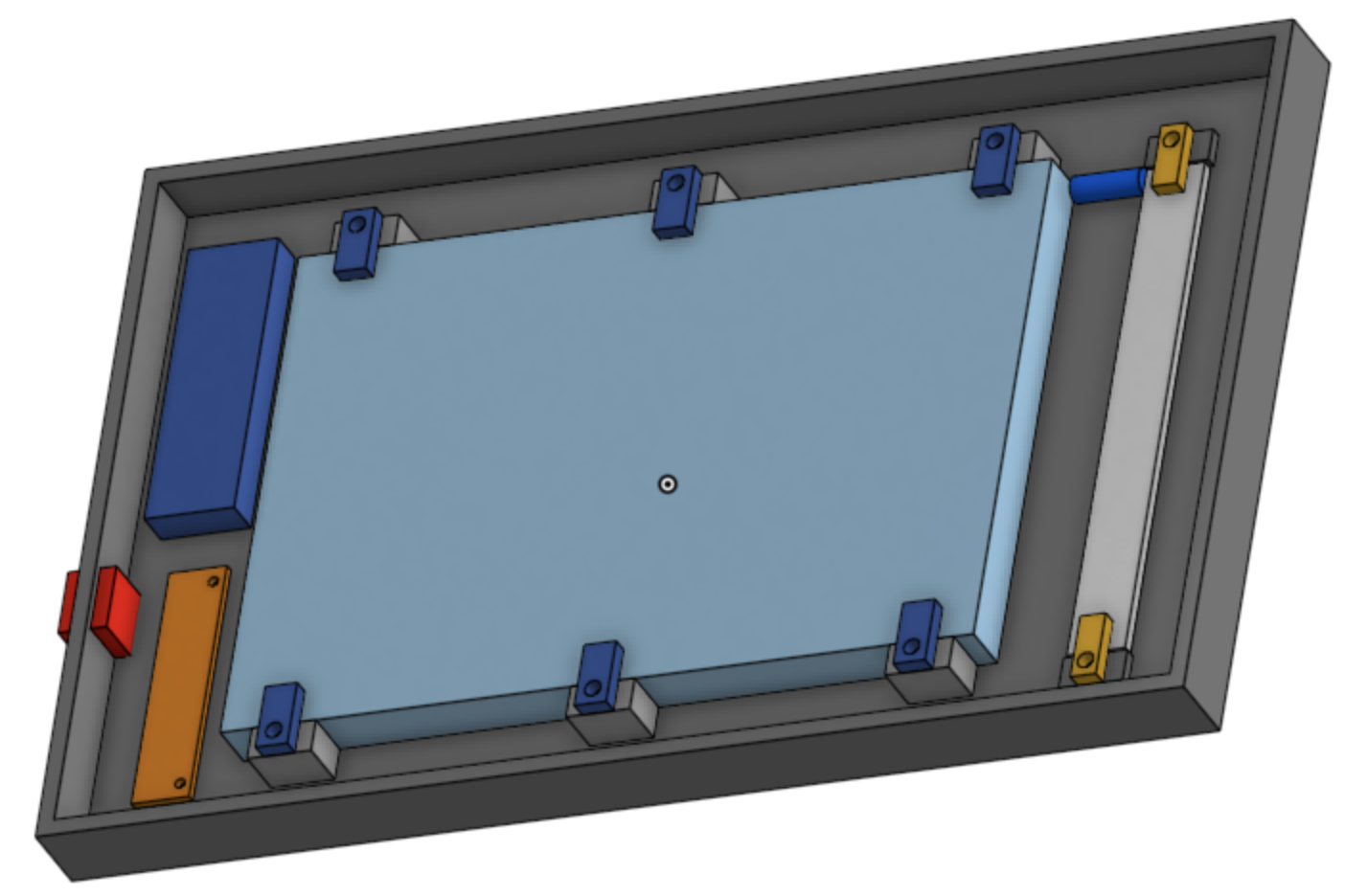
Red Box = Switch, Light Blue Rectangle = Transparent material, Dark Blue Rectangle = Battery, Orange Rectangle = Splitboard. The rectangles in the corner connect the main structure to the transparent material so they move as one. Dark Blue Rectangle = LED light. The LEDs are attached to the structure by having a slot attached to the structure. This ensures that the LEDs are kept in place.
July 8
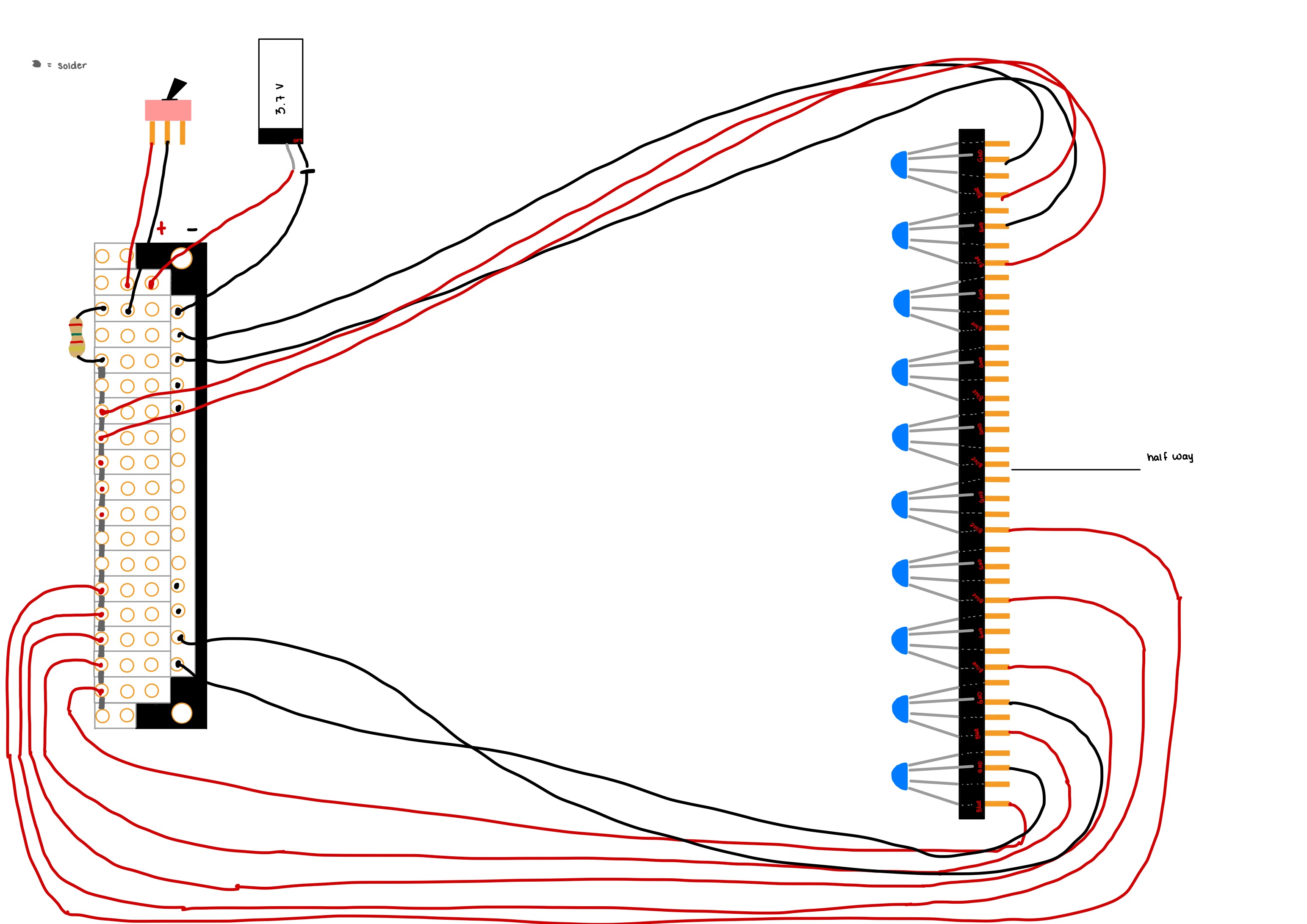
Schematic of my idea on how to arrange stripboard, battery, switch, LEDs and wires.
Today I spent the majority of the day trying to figure out how to transfer what I did on the breadboard with the LEDs, switch and battery to a stripboard. Afterwards, I got a basic schematic done that I thought was good. I started drawing some ideas for the overall structure. The structure has to hold the stripboard, wires, battery, LEDs and the switch. After I came up with a drawing, I was having some trouble visualizing whether the idea would work out or not. To get a sense, I started to CAD my idea on Onshape, but this is my first time using Onshape so CADing it up is taking me longer than usual since I have to look up where certain buttons and functions are. Tomorrow I plan to keep CADing my current design and iterate upon it. After I iterate a couple times, I plan to discuss with EmJ my iterations, and how to improve them and then eventually move on to making the structure.
9. WEEK 2 (July 1-5)
July 3
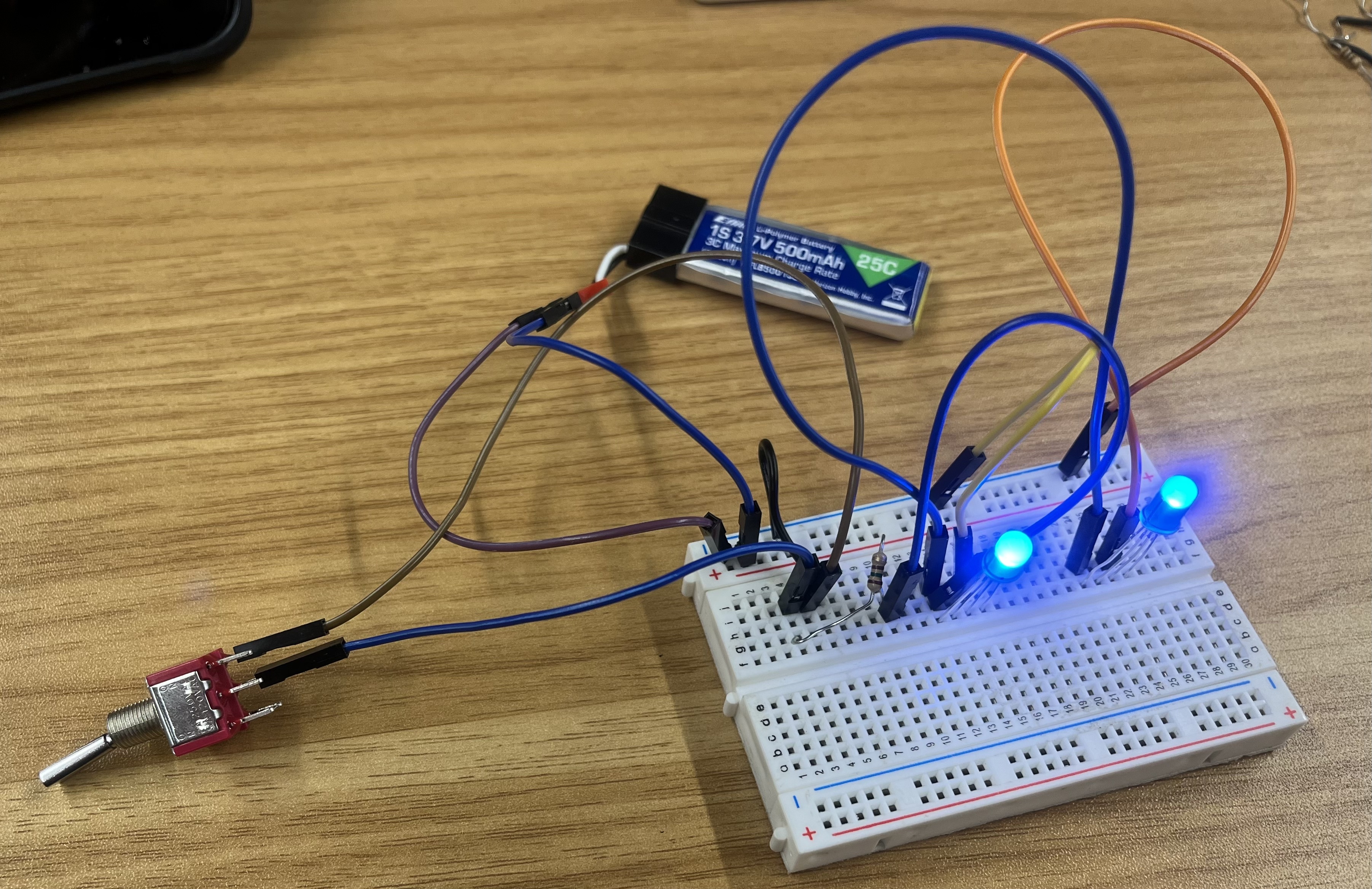
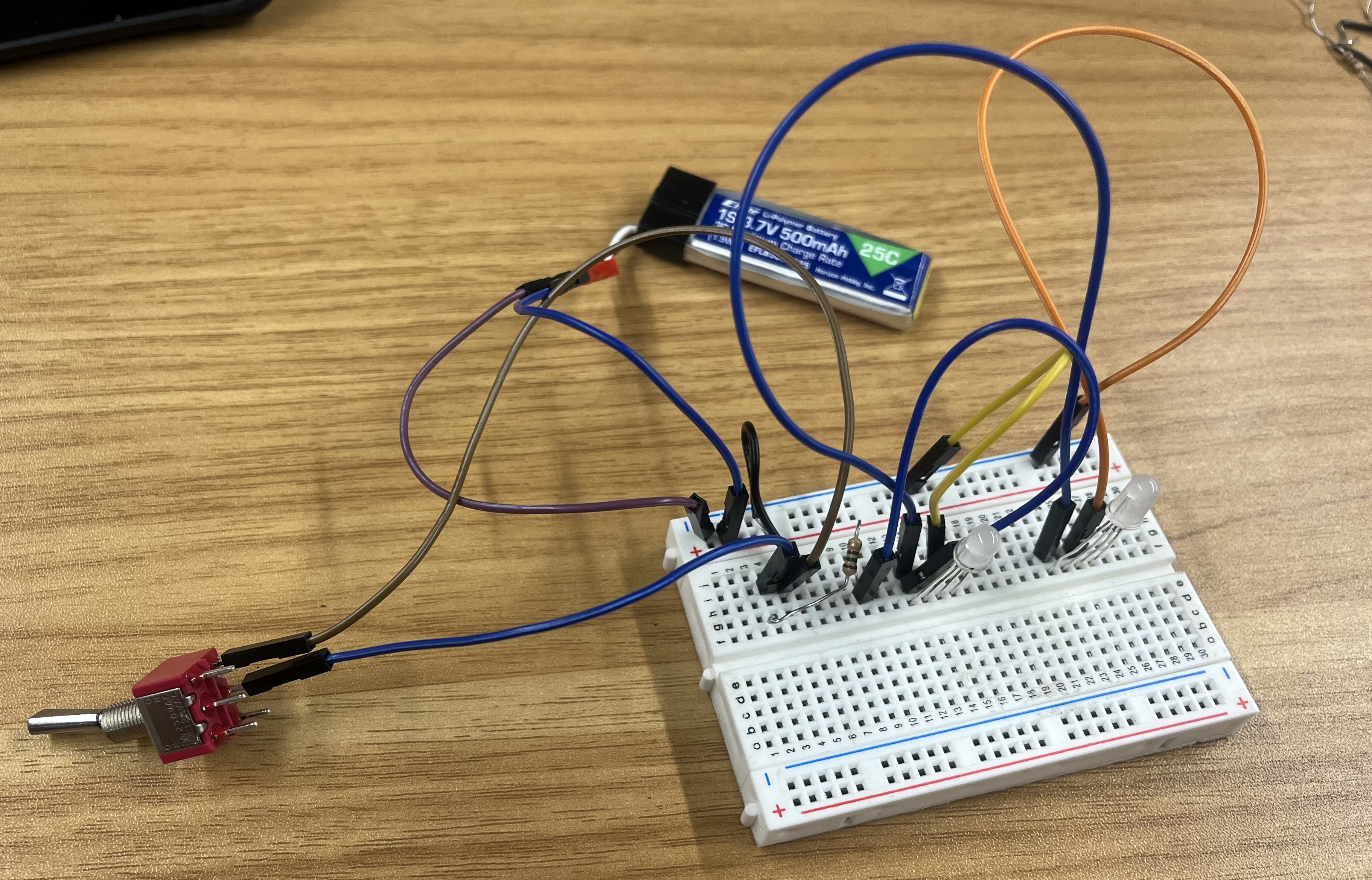
Today I was mostly figuring out how to have the RGB LEDs in a row and turn on simultaneously on the breadboard without the Arduino and instead use a battery. Additionally, I had the LEDs turn on with a switch. First I did this on Tinkercad, then I moved on to actually building it. After I completed this, I learned how to solder. I practiced soldering by soldering some pins to wires. Then I also learned how to use the heat shrink. I thought soldering was pretty fun, it was easier than I expected it to be.
July 2
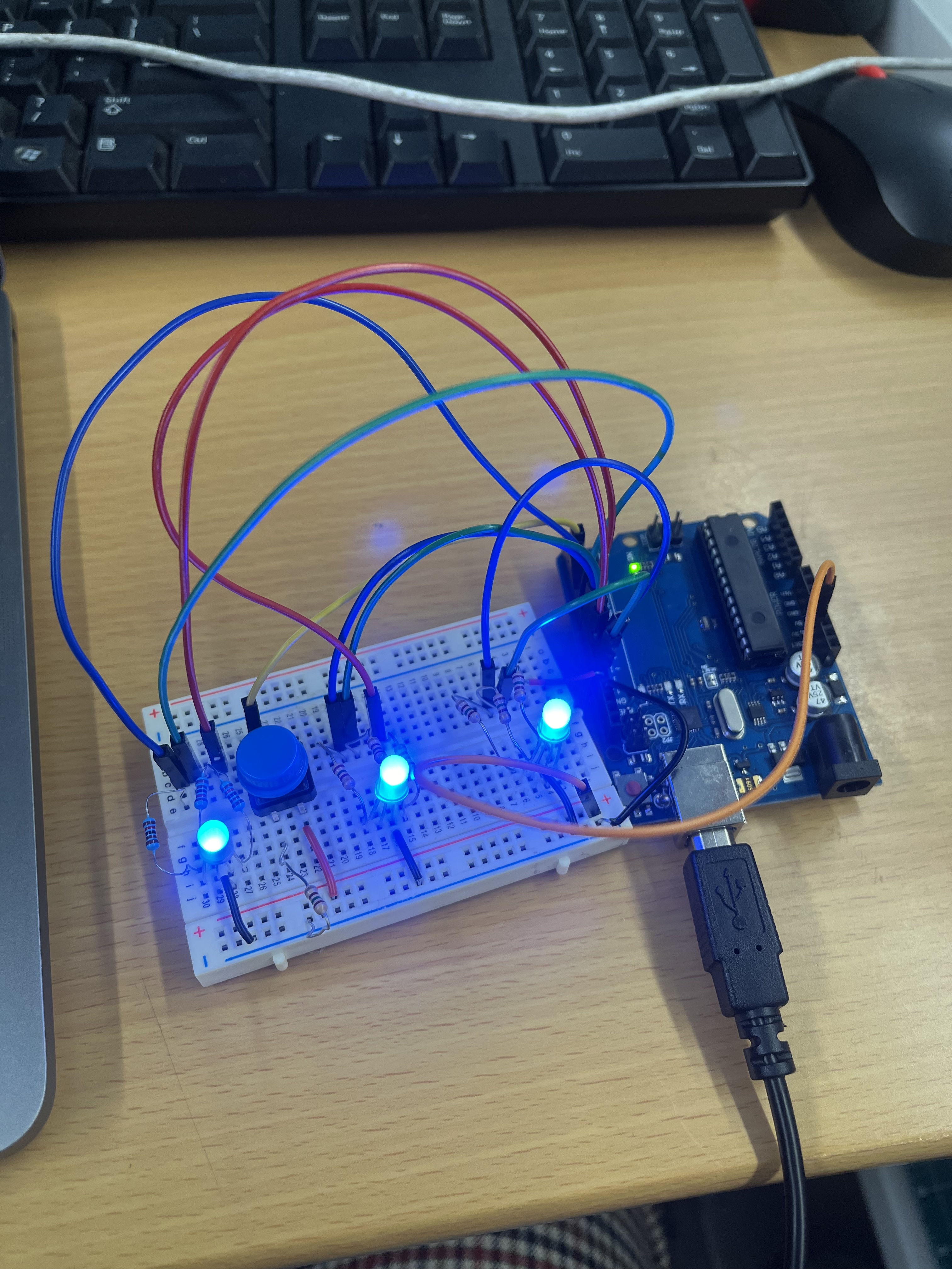
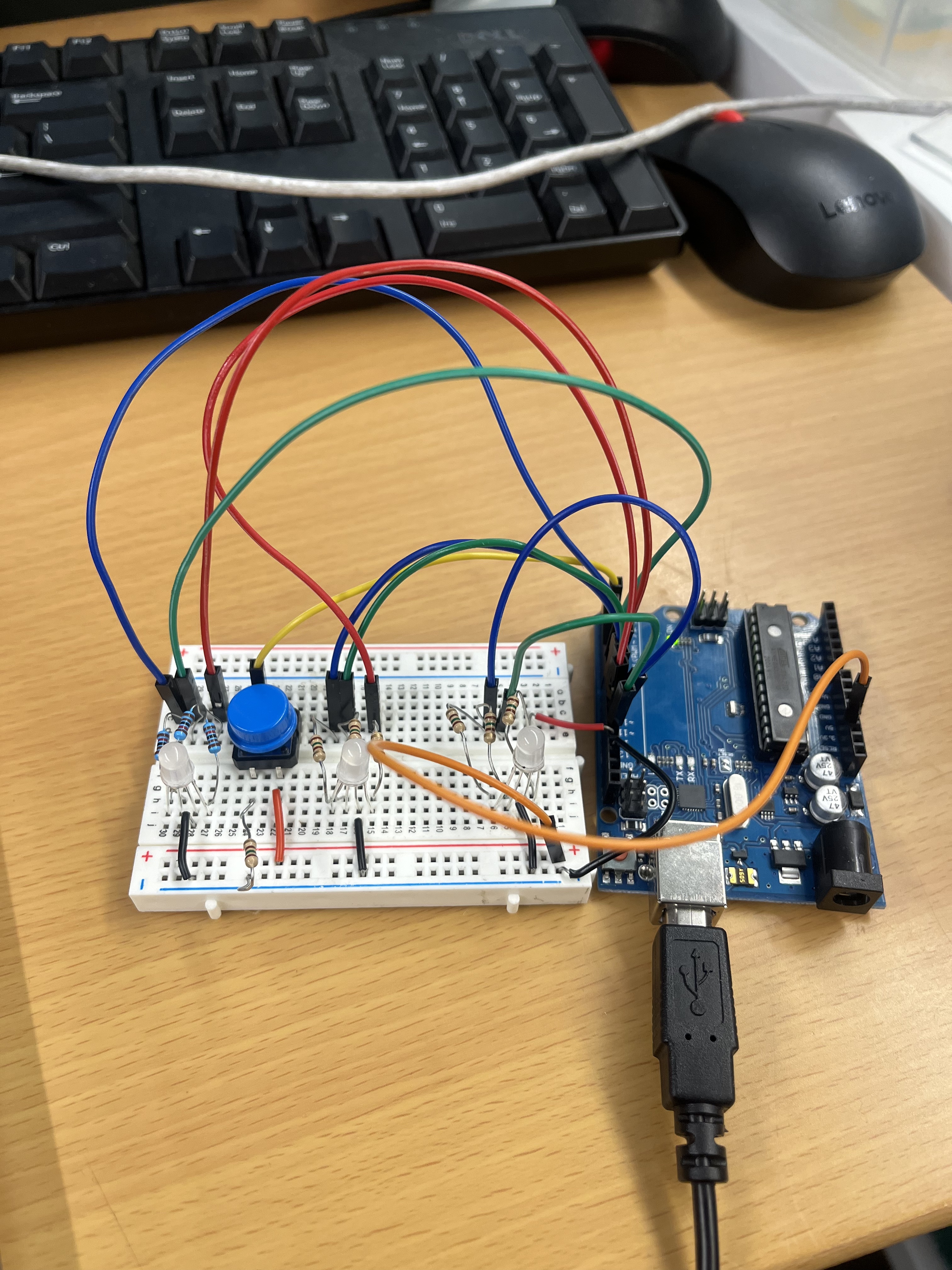
Today I continued to play around with the Arduino. This time, however, I was working on how to get a RGB LED light to work. After that I then worked on getting multiple LEDs on the breadboard and working, so that they all light up at the same time and with the same color. Finally, I got a button working so that the lights would turn on and off with the button being pressed. Some next steps are making the same configuration but without an Arduino and instead using a battery. To get this started, I am going to use Tinkercad. Also, I am going to start working on building and CADing the structure and housing for the LEDs and the battery and anything else that is going to be used.
July 1
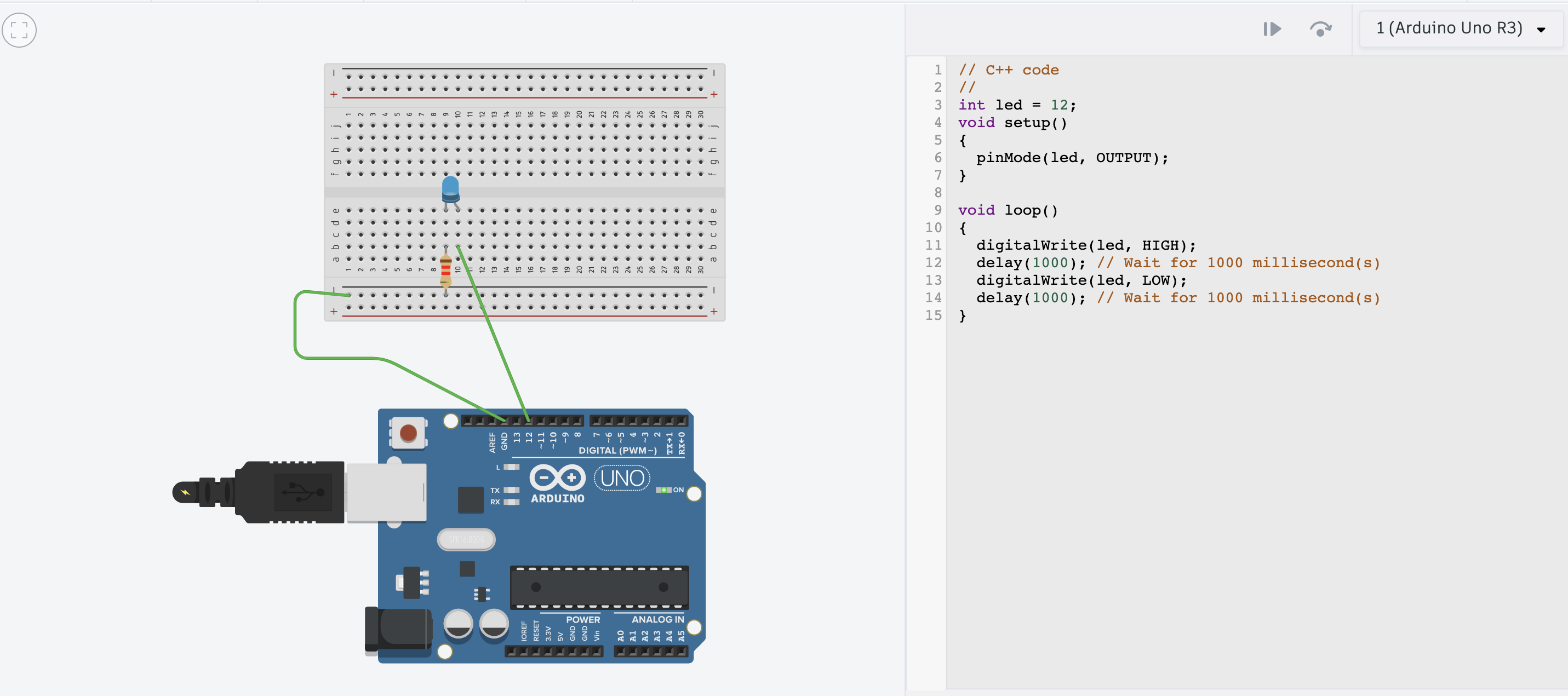
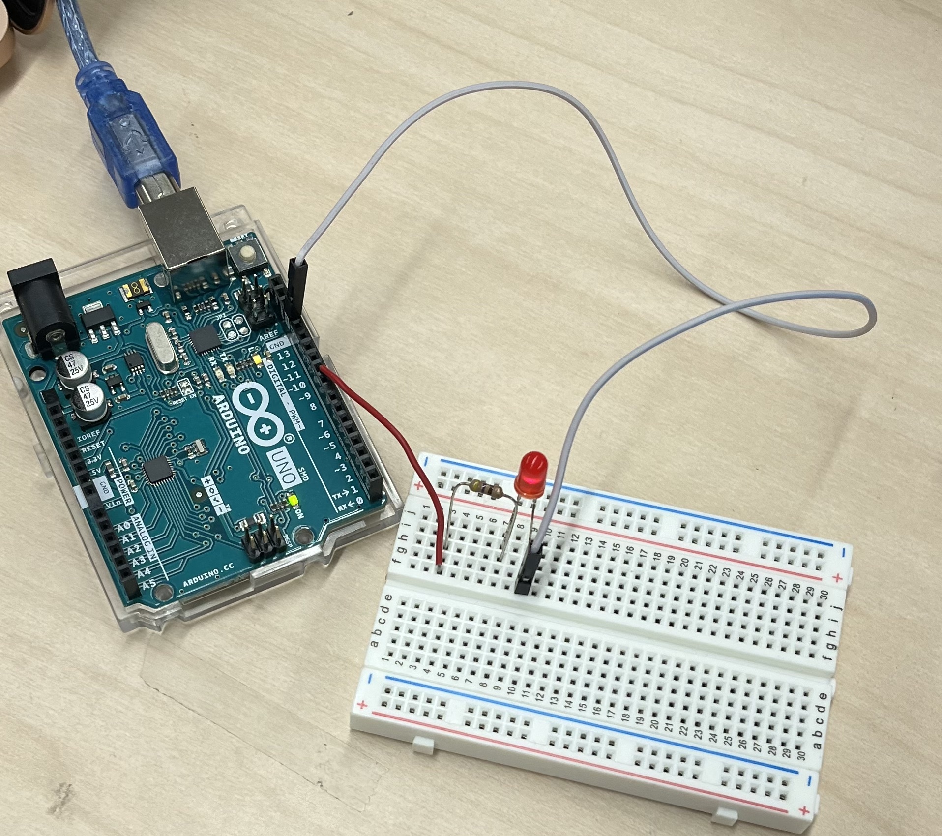
Today I read some papers regarding some testing rigs for the gecko grippers. After I read up on that, I started playing around with Arduinos, since I have not used them before. First I went on Tinkercad to play around with circuits and follow some tutorials. Afterward, I played around with the hardware. My first Arduino project was making a light blink.
- Huh, T. M., Liu, C., Hashizume, J., Chen, T. G., Suresh, S. A., Chang, F. K., & Cutkosky, M. R. (2018). Active sensing for measuring contact of thin film gecko-inspired adhesives. IEEE Robotics and Automation Letters, 3(4), 3263-3270.
- Chu, Z., Wang, C., Hai, X., Deng, J., Cui, J., & Sun, L. (2019). Analysis and measurement of adhesive behavior for gecko‐inspired synthetic microwedge structure. Advanced Materials Interfaces, 6(12), 1900283.
- Eason, E. V., Hawkes, E. W., Windheim, M., Christensen, D. L., Libby, T., & Cutkosky, M. R. (2015). Stress distribution and contact area measurements of a gecko toe using a high-resolution tactile sensor. Bioinspiration & biomimetics, 10(1), 016013.
10. WEEK 1 (June 24-28)
June 28
Today I attended my first entire lab meeting. During this meeting all the undergrads briefly presented on what they learned this week. Then after we presented, Jun En presented what he was researching. It was cool to see the drones flying around and the video using gaussian splatting. Then I worked on a previous ME 1 Pset that involved the gecko gripper for flat panels. After that EmJ went over the Pset and went over a starter project and some other papers. The starter project consists of making a way to quantitatively test the gecko gripper tiles. On Monday I plan to start brainstorming on some ideas in how to build this testing rig.
- Gecko Gripper ME1 Pset
- Parness, A., Heverly, M., Hilgemann, E., Copel, D., Wettels, N., Hilgendorf, T., ... & Kennedy, B. (2013). On-off adhesive grippers for earth-orbit. In AIAA SPACE 2013 Conference and Exposition (p. 5533).
- Parness, A., Hilgendorf, T., Daniel, P., Frost, M., White, V., & Kennedy, B. (2013, March). Controllable on-off adhesion for earth orbit grappling applications. In 2013 IEEE Aerospace Conference (pp. 1-11). IEEE.
June 27
Today the lab went on a retreat to Butano State Park. There I wrote down my goals for the summer and presented them to the lab. Afterwards, we all went on a hike and then to Pigeon Point Light Station State Historic Park. I enjoyed hanging out with the lab and getting to know everyone.
June 26
Today I reviewed some of the papers that EmJ linked. EmJ also showed me, Abi and Saad how to use the Form Lab 3D printer. After that, the three of us were brainstorming design ideas for the tiles used for the gecko gripper project. After lunch, I sat in on the adhesives meeting. After the meeting me and some other people organized two other bins in the lab that contained foams, meshes, and other materials. Afterwards, EmJ met with me, Abi, and Saad to further discuss the gecko gripper project and some more details regarding the design and the next steps and goals.
June 25
This morning I helped clean the lab. After most of the cleaning was complete I was then introduced to the gecko gripper and what the project goals were for that specific project. Additionally, EmJ linked some papers for me and the other undergrads to read to get some background knowledge of the project. Afterwards at around 3:30 pm the Da Vinci Summer Camp, which is a middle school group, toured the lab. It was nice seeing their reactions and their enthusiasm for the projects that were being worked on in the lab.
- Hawkes, E. W., Jiang, H., & Cutkosky, M. R. (2016). Three-dimensional dynamic surface grasping with dry adhesion. The International Journal of Robotics Research, 35(8), 943-958.
June 24
Today I had a brief meeting to go over the BDML website and how to add my profile page. Then I went into the lab and was introduced to some of the projects. Then I had a meeting for SURI to meet the other SURI students and to go over some logistics. After lunch, I went to the biology building to see frogs that are used to test TadBot. Finally, EmJ demonstrated on the CNC, how the molds are made for the gecko adhesive.