SuperSCAMP is the second generation multimodal robot, after SCAMP. The focus of SuperSCAMP is robustness in repetitive performance through more agile controller, well-defined mechanism design, and optimized electronics.
On this page, I will be documenting the different iterations of design considerations, starting from beginning of 2018. I hope this page will explain why certain designs were made and how they performed.
StephanieMoon May 15, 2018
Overview: Past, Present, Future
SCAMP
Before I arrived, SuperSCAMP had been worked on by Alessandro, Drew, and Andrew ( AndrewsLogBook ) from Summer 2017. We wanted to scale up SCAMP, which was light and small, with a climbing mechanism approximately 2x the quad length. However, this would mean more thrust and battery life would be required. Additionally, scaling introduces issues in strength, stiffness, and weight.
When I picked up, the robot could perch pretty reliably using bidirectional motor and position PID controls. Detaching was yet unreliable because the motors' direction switching speed was too slow.
In terms of the physical mechanism, the fast design and build cycles had led to higher mass, particularly in frame and wiring, and due to many experimental tests, the robot was left with only one foot with scarcity of spines. The foot could rotate axially because the carbon fiber bow-spring was a rod attached to the body with superglue and strings. This behavior is undesirable because the feet should be parallel to the wall for controlled gait. Some room for improvement included:
- design a takeoff tail to help the robot "push off" from the wall
- design center of mass closer to wall so that the spines need to endure smaller loads
- optimize spine design for load sharing
- improve climbing mechanism with reduced axial rotation
- reduce weight by careful component selection
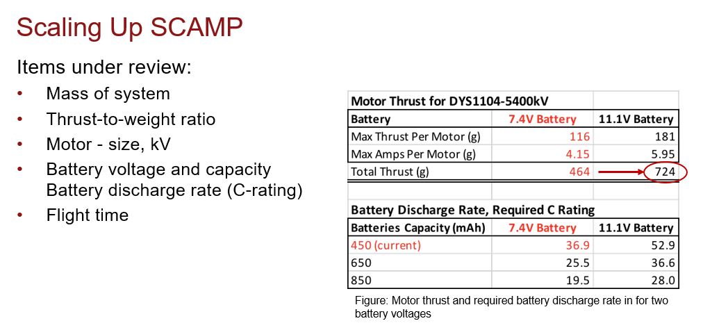
- review motor, battery, electronics choices to increase thrust to weight ratio
- ensure propeller doesn't hit wall
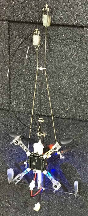
The state of SuperSCAMP in January 2018. As seen on right, the three levels of the robot is quite bulky and leads to center of mass relatively far from the wall when climbing.
Left: The spines were damaged from extensive testing. Right: The foot could rotate axially
Drew has been focusing on the electronics
Controller Inputs
(... state diagram, software documentation...)
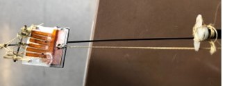
Take-off tail (Feb 2018)
A previous idea for detaching from the wall was to rotate the rotors to push away from the wall and switch the rotors' direction to fly away. However, Alessandro discovered that the speed of direction change was too slow for effective implementation. Thus, our new idea was to have the robot disengage its feet from the wall (by wiggling), create a pivot against the wall, and rotate about the pivot as the robot passively falls. Then the rotors can turn on for flying. After some considerations for a purely mechanical mechanism for deploying the pivot, we decided that a simple servomotor-controlled pivot tail would work most reliably. Quick experimental testing against a wall showed that the design was promising.
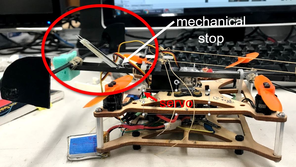
The takeoff tail has two small nails as pivot points against the wall for the robot to rotate about. The mechanical stop ensures that the pivot is in the desired location. The picture shows the tail in its deloyed state.
Respect the Spineology!
Climbing with spines is a topic that has been studied for many years in BDML. "Designing Compliant Spine Mechanisms for Climbing" by Asbeck, Cutkosky (2012) presents a stalk model for designing spine mechanisms. The big picture is that we should design spines so that the probability of spine engagement with asperities on the wall is maximized and the forces applied on the spines do not exceed the force limits of failure.
Some key takeaway messages include:
- Probability of spine engagement with wall depends on spine tip radius, shapes of asperities, coefficient of friction, loading path
- A "foot" of parallel spines need some suspension system that
- distributes overall tangential and normal forces evenly (load sharing)
- allows independence between adjacent spines
- maintains orientation (e.g. doesn't rotate axially)
- For spine load sharing the spring constants should be designed s.t.
- kxx (normal dir) is small s.t. all spines can initially make contact with and drag along the wall
- kyy (tangential dir) is moderate s.t. the earlier engaged spine doesn't run out of travel before its neighbors engage. Softening spring also allows the neighboring spines to catch up.
- kxy is moderate and negative s.t. normal force decreases and becomes negative as we stretch down tangentially
- 30 deg initial contact angle with wall works well
Attach:Asbeck.jpg Δ This figure in the paper shows the loading paths of spines and the force limit envelope.
As we move forward in spine design, I should respect the Spineology!
Compact Body
From Spineology and drawing a moment diagram (seen below), we learn that we can increase the probability of staying within the safe region if we minimize the normal and tangential forces experienced by each spine. We can achieve this by
- decreasing the robot mass
- bringing the robot's center of mass closer to the wall (r1)
- moving the point of contact (Ao) farther from the spines (r2)
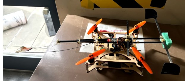
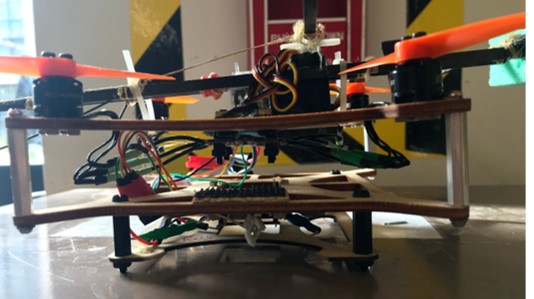
The previous design had three layers - top layer for the actuators, second layer for the battery, and the third for the Crazyflie microcontroller. Because the robot's mass is heavily contributed by the four rotors and the battery, I decided to re-design the frame to have one layer. On the top side can lie the actuators, battery, and robors while on the bottom side can lie the microcontroller.
(... battery near wall, one floor, ...)
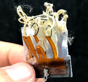
Spine Design (April 2018)
(.... modeling, optimization, crimp method, fabrication difficulties,etc. ...)
Climber
(.... hinges, shorter legs, DC motor, cam, cyclic&loading paths, etc....)
Updated Modules + Software (June 4, 2018)
Now that the climbing mechanism should work (theoretically), I am now moving onto software. There's a lot of updates to be made since there are new hardware modules and the dynamics of the robot has changed. The modules on board are:
- 4 brushless DC rotors for flying
- 1 brushed DC metal gearmotor for up/down climbing
- 1 servo motor for in/out climbing
- 1 servo motor for takeoff tail
- 1 electronic speed control (ESC) [1]
- 1 Crazyflie 2.0+ z-ranger (expansion deck) [2]
- 1 battery
- voltage regulators, bypass caps, resistors, switches
- frame, bumper, mounts
[1] An ESC is basically a microcontroller that regulates and controls the brushless motors. It allows bidirectional control and dynamic braking. It also allows a higher PWM frequency, resulting in lower latency and better flight stability. Useful link on Crazyflie+ESC: https://www.bitcraze.io/2015/06/interfacing-crazyflie-2-0-with-external-motor-controllers-part-2-firmware/
[2] https://wiki.bitcraze.io/projects:crazyflie2:expansionboards:index With the considerable amount of electrical components, I may have to design a PCB later.
Some of the major changes to be made are:
- There was a separate 3.7V battery for the Crazyflie and one for the rest of the robot. Drew suggested that we use one battery to power everything to prevent the spurious event where the Crazyflie battery dies while all other modules still powered. I just have to ensure the power to the Crazyflie has a fast discharge rate of 25C (≥ 80%). The hardware specs: https://wiki.bitcraze.io/projects:crazyflie:hardware:explained