Category: TactileSensing
Tactile Sensor Demonstrator
On this page... (hide)
1. Overview
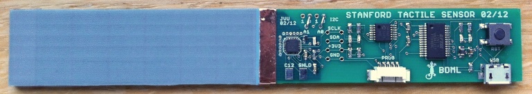
The 'Stanford Tactile Sensor' board is a tabletop demonstrator meant to familiarize users with the performance of capacitive tactile sensors designed in the BDML. An array of 12 taxels arranged in a 6 wide by 2 tall pattern sits on the left side of the board. Each taxel is approximately 1 cm x 1cm in size. Data are returned at a rate of 100 Hz via USB/serial connection; the rate can be significantly higher for custom solutions. For information on the sensor design and construction see: CapacitiveSensorDesign.
2. Required Software
- FTDI USB to serial converter virtual com port driver (common, may be installed already): FTDI Driver Page
- MATLAB *.m file to run sensor or Windows executable if MATLAB is not available (MATLAB recommended if available): MATLAB *.m file (zipped) or Windows executable. Alternatively, you can write your own program that communicates with the board using a serial port (see Direct Serial below).
3. Demonstrator Viewer Instructions
- Download and install the appropriate FTDI USB to serial converter virtual com port driver if it is not already installed on your system. This will allow the sensor board to communicate over a serial connection with your computer.
- Download either the MATLAB *.m file or the Windows executable file to run the sensor. Note that the live display feature of this program operates most smoothly on Windows and Linux MATLAB installs.
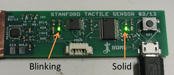
- Plug the sensor into your computer and verify that there is one blinking green LED and one solid green LED as shown below. If the lights are not functioning as shown, unplug the board from your computer and plug it in again.
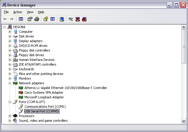
- Determine which serial port your computer has assigned to the tactile sensor board. In Windows, you can see this in the device manager. On a Windows machine, just type "devmgmt.msc" in the run dialog to open device manager quickly. You will see a COM section with an associated COM number next to the FTDI device. You will need this number when you run the display program. The image below shows a typical device manager window with the com port associated with the tactile sensor highlighted.
- If MATLAB is available, open it and run the *.m file. If MATLAB prompts you to, change the working directory to the directory where the file is located. Follow the prompts in the command window to enter the COM number and the time you would like the display program to run.
- If MATLAB is not available, run the executable file. This file is an exported version of the *.m file from the MATLAB environment. It may take a few seconds to start up. Follow the prompts to enter the COM number and the time you would like the program to run the display.
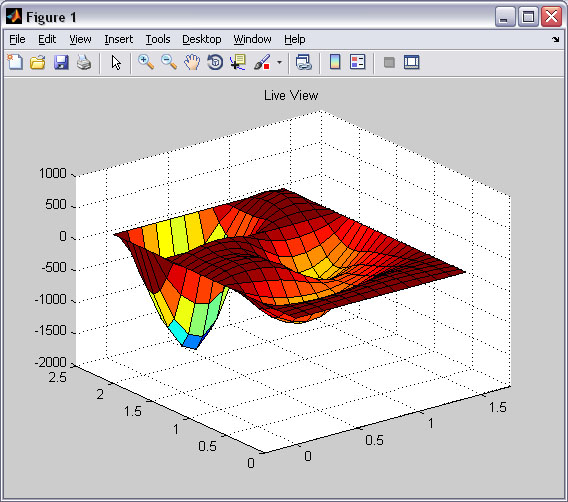
- The sensor display program should be running and you will have a live display of sensor data. Press on the active areas of the sensor. When the running time that you selected has passed, the program will stop and display a record of the data from the sensors over the run. You may access raw data in the MATLAB environment through the 'sensor_data_history' array (not available from executable). An example of the live display is shown below. Data is interpolated to create a 3D image to highlight the ability of the sensor to locate the center of pressure of a contact with subtaxel resolution.
4. Direct Serial Communication
The Stanford Tactile Sensor demonstration board communicates to a host computer through a standard serial port via an onboard FTDI USB to serial converter IC. It is possible for a user to communicate with the board directly rather than through the supplied viewer program. To communicate with the board, first install the FTDI drivers above and then use these settings to establish a com connection with the serial program of your choice:
- Baud rate: 115200 kbs
- Data bits: 8
- Stop bits: 1
- Parity: none
- Flow control: none
The board accepts a few commands to begin or end data transmission. The command structure is outlined here.
Commands consist of three bytes. The first and last bytes are framing bytes and are always 0x02 and 0x03 respectively. The middle byte is the command. There are 4 possible commands:
- Stream: 0x80
- Sample: 0x81
- Idle: 0x82
- Status Request: 0x83
For example, to request a single sample of tactile data (one full set of 12 readings, one from each taxel), you would send this sequence over the serial port:
[START_BYTE SAMPLE_COMMAND END_BYTE]
or
[0x02 0x81 0x03]
The board will then take a sample and send its result in a data packet described below.
Data returned from the board comes as a framed packet with header information. Again, 0x02 and 0x03 are used as start and end bytes to frame the data. The bytes in the middle of the framing bytes contain information about the amount of data being returned, the type of data, and the data itself. If the user has requested sensor data, it will be returned as a stream of 16 bit values broken into their least significant byte (LSB) and most significant byte (MSB) with the LSB returned first in the sequence. A typical returned sensor data packet takes this form:
[START_BYTE DATA_LENGTH DATA_TYPE DATA1_LSB DATA1_MSB DATA2_LSB DATA2_MSB... DATA12_LSB DATA12_MSB END_BYTE]
or
[0x02 0x19 0x10 0x## 0x## 0x## 0x##... 0x## 0x## 0x03]
The data length byte, 'DATA_LENGTH' or 0x19, tells the user how many bytes to expect before the end framing byte arrives (does not include the end framing byte in count). This length includes the data type byte, 'DATA_TYPE', which will have a value of 0x10 for sensor data. A typical returned packet will have a data length of 0x19 or decimal 25 bytes. This accounts for the data type byte and the 24 sensor data bytes for the 12 sensors with LSB then MSB data returned for each.
If the user requests streaming data rather than a single sample, data packets of the same form as shown above for a single sample will be returned at 100 Hz. To stop the streaming of data, the user can send the idle command. Note that streaming data is returned with higher regularity and at a faster rate than is possible with sequential single sample requests.
Alternatively, the user may send a status request. In this case, the returned packet will be similar to a sensor data packet, except that the 'DATA_TYPE' byte will take the value 0x11 to indicate a status message. The status message is a single byte and follows the 'DATA_TYPE' byte. An example returned status packet takes the form below:
[START_BYTE DATA_LENGTH DATA_TYPE STATUS_BYTE END_BYTE]
or
[0x02 0x02 0x11 0x0# 0x03]
Where the status byte, 'STATUS_BYTE' may take on the following values:
- Initializing: 0x00
- Idling: 0x01
- Streaming: 0x02
- Error: 0x03
4.1 Running under Unix
A loadable kernel module (ftdi_sio) is included in Linux kernels 2.6.31 and later. When you plug in the device it will automatically show up as /dev/ttyUSBx, where x is the next available number starting with 0. This can then be used as a standard serial interface via C, python, etc.
If you experience problems, unplug the tactile sensor board from the computer and plug it in again. Please email John Ulmen (ulmenj at stanford.edu) if you need additional support.