category: SummerBlogs
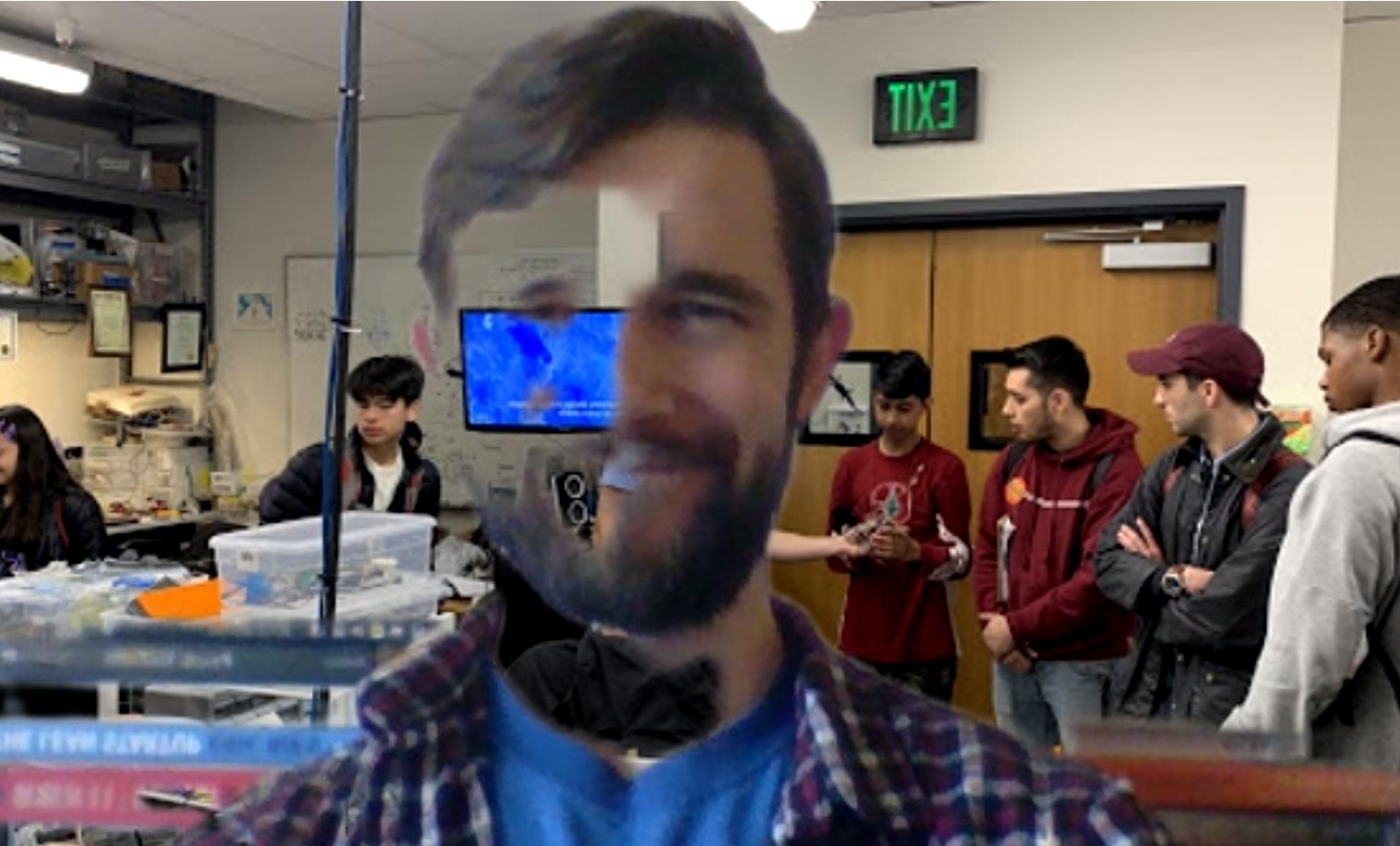
Simon (not) in BDML for spring and summer 2020
Spring/Summer blog - update every few days with new findings.
Week 1
Just getting settled into the lab. It has been great getting to meet people and to learn about their respective projects. I have started to review previous FlyCroTug designs and results, and to evaluate them against future goals for the project.
On the side, I also got the chance to work with Capella to help with the post processing of some Gecko Adhesive. It was great to get a better feel the manufacturing process and how the Gecko adhesive works!
The rest of the week was spent getting trained for the different spaces and looking into the manufacturing of microspine grippers. Microspine grippers allow the FlyCroTug drones to passively adhere to rough surfaces, such as roof tiles, bricks, or concrete, allowing them to exert much larger forces on the environment. BDML has experimented with several different manufacturing methods to make these grippers. One method uses a combination of resins (one stiff, one elastic) to allow the stiffness of the spines to be tuned in the normal and tangential directions independently. An alternate method sacrifices the tune-ability in favor of weight reduction and manufacturing simplicity, by simply adhering the spines to Kapton film fingers. The latter method seems promising for aerial vehicles, but needs to be recreated and optimized for the future FlyCroTug platforms. I have also been toying with the idea of directly machining microspines and bow-spring style elastic elements from thin sheets of spring steel or Nitinol. This would drastically reduce the manufacturing complexity, but would come at an added weight cost. More tests to come next week!
Week 2
My second week was full of testing and rapid prototyping! After fixing the lab's Ultimaker 3D printer, it was off to the races, creating new jigs and test assemblies.
Continuing with the Kapton film finger design, I investigated different manufacturing methods to facilitate quickly making new microspine arrays. I tested different adhesives, surface treatments, and jig designs to quickly and accurately align spines prior to bonding them to the adhesion.
The most reliable method I found was as follows:
- Laser cut fingers with the desired size and pitch out of Kapton, fiberglass, or a thin sheet material of choice.
- Rough the ends of each finger with sandpaper and subsequently clean it with isopropyl alcohol.
- Use a 3D printed jig to align the selected fish hooks to the ends of the fingers.
- Apply a generous band of JB weld quick cure epoxy to the fingers and place the jig on top.
- Using a toothpick or similar, brush excess epoxy over the tops of the fishhooks to ensure the center of the hook is fully encapsulated.
- Allow sufficient time for the epoxy to cure to full mechanical strength.
- Carefully remove the 3D printed jig.
- Use side-cutters or similar to cut the shangs from the fish hooks.
- Use an exacto knife or similar to carefully cut through any epoxy bridges between the fingers.
- Enjoy your new microspine array!
Following this testing, I came up with an idea to use ribbons of thin film (such as Kapton or thin fiberglass sheet) to create a cassette of coil springs on which microspines could be attached. This method of manufacturing greatly reduces the complexity, compared to the previous SDM methods, and can be quickly prototyped and tested. This method also allows the normal and tangential stiffness, and the spine travel distance to be easily tuned by changing the width and thickness of each individual "finger". For thin films, "thickness" can be changed by simply layering multiple strips together. Tony helped me further develop the idea and started working on a collapse-able truss design to actuate the gripper. Prototyping hit a bit of a snag due to precautions taken to limit the spread of COVID-19. The labs transitioned to remote work only, and my work on microspines will be put on hold.
Week 3
Stanford has now officially shut down all "non-essential" on-campus research operations. Students are being asked to leave the campus as a precautionary measure. In response, I have returned home and will work remotely until the social-distancing measures are reduced. It took some adjustment to remote work and to shift the focus of my research away from hardware and towards software. One of the key aspects of the FlyCroTug project where there is the potential for some development is on the automation of the perching procedure. Prior investigations by BDML in perching utilized human pilots with constant line-of-sight on the vehicle. Even under these conditions, not all perch attempts are successful. This is in part due to the complexity of the maneuver and in part due to the stochastic nature of the surface asperities which micro-spine grippers attach themselves to.
Previous work has identified optimal flight trajectories (target normal and tangential velocities) for a perched landing. Additionally, some characterization of perching failures was conducted. This included the identification of failed vs. successful perching attempts using the quadrotor's sensory information. Acceleration data was found to be the most useful and previous experiments showed 90-95% identification accuracy. I have started investigating the state-of-the-art for non-linear quadcopter control. A nonlinear controller will likely be required in order to maximize the change of success on a vertical perching attempt, which requires a 90 degree pitch turn. Automating perching will be necessary when the drone is being flown autonomously, but could still be beneficial when manually flying with limited line of sight or a high-latency video stream. Additionally, automated perching maneuvers could improve perch location precision, allowing for specific vantage points to be used, and reducing the minimum landing site size requirement.
Week 4
This marks the end of my first week in isolation - fortunately my room has plenty of natural light and I have no shortage of reading. This week has been spent continuing to learn about non-linear control techniques for quadcopters, including methods developed by ETH Zurich's Flying Machine Arena and UPenn's GRASP Lab. In preparation for future simulation work, I have also been brushing up on ROS and Gazebo.
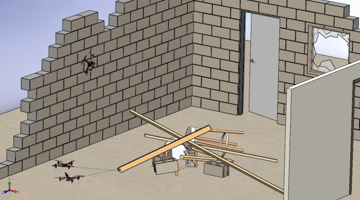
A perspective view of the cluttered simulation environment
Week 5
Continuing on my quest to better understand ROS and geometric control, this week I worked on using an open-source geometric controller to control a simulated quadcopter in Gazebo. The controller is based on Lee's geometric controller on SE(3) and is implemented for the PX4 flight controller, which means it will port easily to hardware when the time comes. I finished going through tutorials for ROS this week as well, which will make future projects much simpler to develop.
This figure shows the geometric controller in action, controlling a simulated drone around a circular trajectory. Of course, the controller is more important when more extreme maneuvers are required.
For the FlyCroTug project, I felt it would be good to create a function diagram for the overall system. This was a useful exercise to determine the inter-dependencies of different aspects of the project, to note relative priorities of tasks, and to more efficiently assign work to the project team. Generally speaking, the project can be split into quite separate sub-modules without impacting overall progress significantly. For instance, while the drone perching system is in development, camera fusion and object segmentation can still be developed by simply manually placing cameras. Similarly, the FlyCroTugs and their grippers could be simulated using a simple pull string with a human operator.
Week 6
I had the chance to connect with BDML alum Matt Estrada (who is currently in a post-doctoral position at my home university, EPFL) this week to discuss his (potentially unpublished) findings and takeaways from working on the original FlyCroTug project and a host of other interesting projects! Matt provided some excellent feedback regarding the strengths and limitations of the original work. As the new FlyCroTug project will have many more moving parts and critical dependencies, Matt's general suggestions were to keep things simple and try to boil down the problem to its minimum requirements. In particular, he suggested investigating alternate perching methods.
Week 7
This week represented a bit of a shift in focus for my work. Given Matt Estrada's advice about simplifying the perching maneuver, there is more uncertainty over what level of control and planning will actually be necessary to instantiate perching for the camera drones. An aspect of the project that has yet to be addressed and that will be necessary regardless of perching method is perch location selection. With that in mind, this week, I have focused on decomposing the "Where to Perch" (WTP) problem. Presuming a map of the environment is known or has been constructed by a previous robot, the WTP problem can be broken into the following aspects:
- Segmentation of the map into contiguous planar (or pseudo-planar) surfaces
- Identification of semantic information for the segmented regions, such as surface roughness or material type
- Identification of the subset of map surfaces which represent feasible perching locations, based on patch size, location, environmental constraints, and semantic information
- Selection of N perch points to optimize the motion capture quality of the resultant camera network
Many of these individual aspects have been developed extensively in their respective fields. However, to my knowledge no group has demonstrated a system capable of automatically determining optimal perch locations on inclined or inverted surfaces. That is where I hope to make a novel contribution to the project. The image below shows a potential workflow using sample images acquired online.
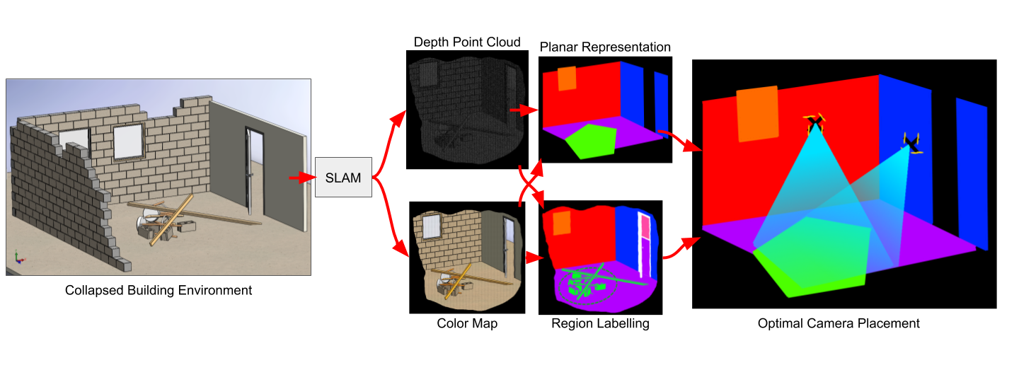
The prospective workflow for the WTP problem. An environment map is input to the system, and optimal perching locations are determined
Continuing in this direction, this week consisted of quite a bit of literature review, as well as some experimentation with various open source models for material identification. Installation of many of the required dependencies was more of a challenge than expected.. More on this to come in the near future!
Week 8
This week was spent continuing my literature review on different solutions for material identification, plane segmentation, and location optimization. From what I have found, 3D camera placement for object reconstruction and motion tracking is a well discussed problem in computer vision. The most common, practical solution for this problem involves a heuristic based optimization method, such as using evolutionary algorithms or simulated annealing. Having some recent experience with Particle Swarm Optimization (PSO), this facet of the problem seemed like a good place to start!
I developed a 2D camera placement optimization program which can take in an arbitrary environment with designated obstructions, a heterogeneous group of cameras to be placed, and a target region where optimal coverage is desired. With these inputs, a PSO routine is used to return local optimum positions for each camera. The image below shows the placement search in progress, along with the resultant optimal result.
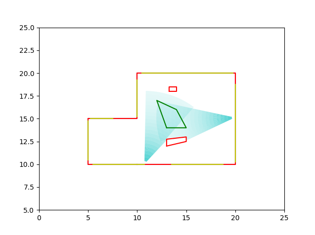
A preview of how PSO samples and evaluates different potential camera placements. Note that the optimization routine runs much faster without visualizing the camera placements. Better placements could be found with different random initializations or increased search time.
Next week will be spent augmenting the program to handle 3D placement, with added variables including camera pan, tilt, and zoom, as well as ceiling placement. As the dimensionality of the problem increases, the settling time will likely decrease. To combat this, I will implement different algorithms, such as greedy assignment of positions and iterative optimization of reduced problems. I'll also continue to review options for plane segmentation and semantic material extraction to feed into the optimizer.
Week 9
This week, I had the opportunity to connect with Roberto Martin-Martin, a post-doc in Stanford's Vision and Learning Lab who had worked on the most recent FlyCroTugs proposal. He was able to offer some key insights regarding my proposed WTP pipeline. In particular, he suggested a few recent neural network architectures, like Mask RCNN and ResNet, that could act as reliable starting points for material classification. He also suggested a change to my proposed pipeline: paralleling plane segmentation and material classification. Most material classifiers offer pixel-wise labelling, which can often result in "noisy" or pixellated segmentation maps. By also including the assumption that discrete surfaces likely have a uniform material composition, it is possible to unify the labels using a simple voting system. This should improve the reliability of the algorithms overall.
On the camera placement side of things, Roberto, and my EPFL supervisor, Fabrizio Schiano, have expressed some concerns over the validity of PSO for camera placement optimization. In particular, because PSO relies on local gradients to traverse the search space, its behavior might be unpredictable or ill-behaved when the search space is discontinuous (e.g. the environment map has holes or missing patches). While in practice, I have found that PSO still converges relatively quickly on robust solutions, I will have to take some time later on to compare between PSO and other methods like grid-search, random-search, and genetic algorithms. Fortunately, the camera placement evaluation framework I have developed should be usable with any of the listed methods.
Speaking of which, here is the camera placement algorithm - now in 3D!
Week 10
This week, I was back to being nose-deep in a literature review of state of the art Simultaneous Localization and Mapping (SLAM) and Visual and Inertial Odometry (VIO). While I won't be developing new mapping and tracking algorithms myself, it is important to make sure that the algorithms I end up integrating into the WTP pipeline are best suited for the projects needs, in terms of sensing and computational hardware requirements, environment representation, map adaptability, and accuracy of the representation.
In the FlyCroTug project proposal, we suggest that the environment mapping and reconstruction can be done offline. With that in mind, the bulk of the computation isn't very time-critical and doesn't require real-time processing. However, once the camera network is established and the FlyCroTugs are interacting with the environment, it could be beneficial if the map is in a form that allows lightweight manipulation of the map as objects are manipulated. Sparse SLAM algorithms typically only track key features in an image and result in relatively lightweight maps. An alternative approach is to use an object-based representation where objects are recognized (e.g. using a Convolution Neural Net). Afterwards, the object can be represented simply be a classifier and a pose. A third option would be to use a hybrid representation, using a dense point cloud or mesh for the environment, and object representations for objects in the environment which can be manipulated.
This week, I was experimenting with different SLAM and VIO algorithms, to get a better idea of their limitations and which would be best suited for our application. The first on the list, ORB SLAM 2, is one of the current gold standards for visual SLAM. The base (and coincidentally the open-source, ROS supported) version of the algorithm doesn't account for inertial information or other odometric information that is available to the robot. This means it relies purely on features it can extract from the video feed.
ORB SLAM tracks ORB (Oriented FAST and Rotated BRIEF) features - which won't mean much to those who haven't studied computer vision (like myself).
FAST refers to Features from an Accelerated Segment Test - a simple keypoint detection algorithm. The FAST keypoint detector (described well here). FAST is essentially a corner detector, which can quickly extract key points by comparing select pixel intensities within a given radius. A drawback to FAST is that it does not extract orientation of keypoints. To solve this issue, the authors of ORB SLAM added an intensity weighted centroid calculation of the corner patches. The relative position of this centroid to the identified corner is used to define the orientation of the corner. This method proves to be remarkably effective and efficient - both ideal for a SLAM algorithm. However, identifying keypoints in a frame is only half the battle. The second half is tracking them between frames. That's where BRIEF comes in.
BRIEF (Binary Robust Independent Elementary Features) is essentially a method of quickly creating a fingerprint for a given region of interest. BRIEF achieves this using a vector of binary features, where each binary feature represents an intensity comparison between two pixels in the region. The number of binary features depends on the patch size and the desired complexity of the fingerprint. ORB SLAM uses these BRIEF fingerprints to track keypoints between frames. Simultaneously, to help compare fingerprints, ORB uses the orientation of keypoints to "steer" the BRIEF feature comparisons - essentially rotating the pixel indices within a target patch to match the respective orientation of the corner. Rotations are kept fast by discretizing the angles and using a lookup table.
The result is a sparse localization and mapping method. When paired with a depth camera, such as RGB-D or stereo, distances can be assigned to each feature, and the resultant map can be made to true scale. In practice, this method works quite well, and can run in real-time on a CPU with relatively high accuracy.
Week 12
Week 13
Week 14
Week 15
Week 16