8/22
I think the interface with the hand is needlessly slow, so I'm considering communicating with it directly without ROS. This might help to remove some delay so that the hand reacts faster to changes in force. However, this would remove the benefits of the actionserver being interruptable and and sending receipt of its action. On balance though I'll keep ROS because it would be a huge pain.
Another problem right now is in relation to more gentle forces. The hand will squeeze too far and then jerk back. But then the force is very low so it will again jerk forward. That is a big impulse which causes the cycle to repeat. The only solution I can think of is to widen the deadband.
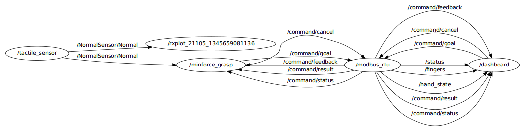
This is the workflow of messages passed through ROS:
8/21
Ideas to prevent queuing on the ROS side: I need to make sure that the action was received and is executing before sending another one. Well really I need to override that action if I receive another one while the current action is being sent. So there would be a global current action field, and I could have a constant rate of that action being sent to the hand. Also the next action is only sent if the last one was received properly. If the action is nothing, do nothing. Also if the action is the same as the last one, do nothing. That might reduce some jerkiness and it will greatly reduce the number of commands sent.
As an aside it's not that bad that Barrett wrote the Robotiq Node using an actionserver, which is a bit more complicated than needed, but this way I can definitely interrupt actions.
Success! I added my own short queue and another thread that tries to run each action at a constant rate, also implementing the ideas above. With an ample deadzone and a reasonable amount of force, I was able to have the hand maintain a force when gripping the sensor. The next things to try is more gentle forces, how low I can make the deadzone, and the P-control. Right now I have a feeling that the P-control is not going to be a significant help.
Sending a command to the hand and getting a receipt of that command takes an average of 0.027s, which means that practically the hand runs at ~37 Hz.
8/20
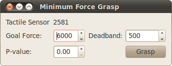
Today I wrote a small GUI for setting the control parameters for the minimum power grasp. Then it uses ROS to interface with the Robotiq hand and the tactile sensor. I've started with just the simple on/off algorithm (P=0) where the hand stops within the deadband of the goal force. This produces a somewhat jerky stepped motion as the hand starts and stops quickly.
The problem I'm having now is that there is a long delay between commanded action and result from the hand when I'm controlling it in this step-wise manner. There seems to be a very long queue of actions for the hand somewhere, either in ROS, the serial connection, or the hand itself. I think there is a queue because there is a clear delay in opening and closing, and even after stopping my program the hand continues to move in the step-wise manner, indicating that it is receiving open and stop commands in succession.
8/17
So it turns out that all of the problems I had with the sensor were from my end. The data received from the sensor was a 16bit unsigned integer for each taxel. When I read the data, I mistakenly read the first byte as most significant and the next as least significant. In reality the values were flipped. So what was happening was that I was magnifying every small change in the sensor value. This also explains the overflowing, because it was happening on my end. This is a plot showing the actual real data received from the sensors, with no offsets.
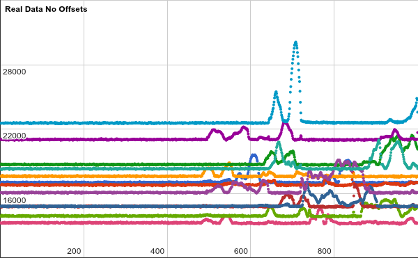
The error is much less, and matches what Matlab shows.
The next things to do are for running the actual demo. To do that I'm going to put everything that I've written back into the world of ROS so that A) there are more visualization tools B) everything is in the same system so even the Adept can play along.
Then for the force control loop there are a few methods. First is a simple check for whether or not the hand has reached the desired force. If it has gone past, it will step-open, or if it hasn't reached it it will step-close. I might need a deadband to prevent a lot of vibrations. Also without a deadband the hand will slowly want to open because it moves faster that way. The other way is to do a simple P control where there is a delay that is directly proportional to the error in the sensor value.
8/16
To eliminate any effects from the Robotiq, I connected the sensor to my own laptop while the hand was far away and unpowered. This plot shows the effect of pressing on the center of the sensor.
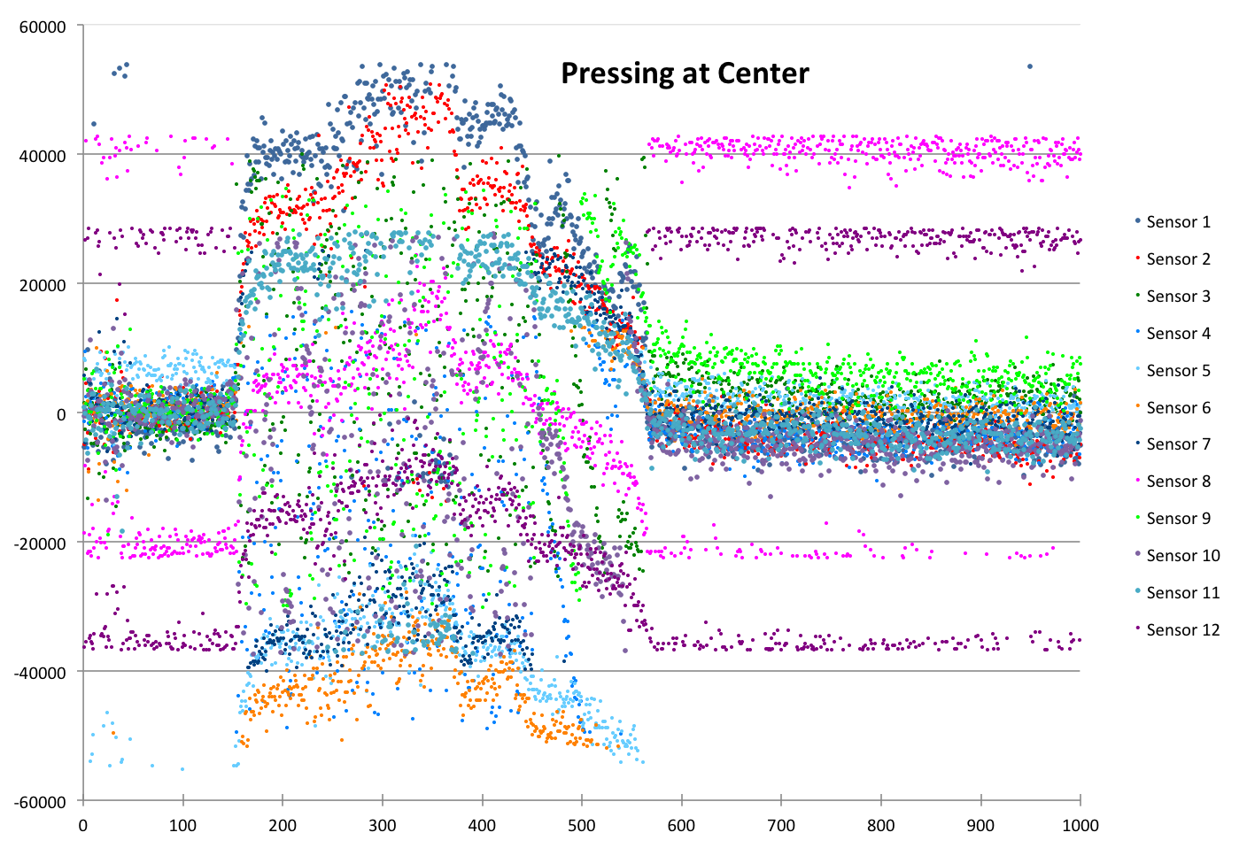
Here I'm plotting the steady state of all 12 sensors without any offset, just reading the data directly from the board.
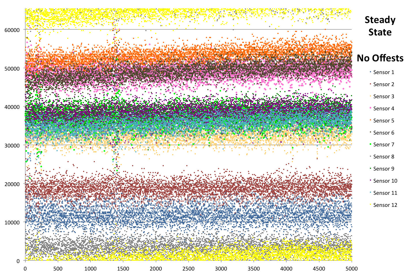
The width of each band looks to be about the same, so one reason for yellow and gray sensors having so much variation is an overflowing integer. As the value of a 16-bit unsigned integer reaches 65,535 it will roll over and become 0. That seems to match what is happening to those sensors.
8/15
I tried different foams covering the sensor, but could not differentiate between the force applied as the hand stepped open and close. Here are plots of the data that I am using for force detection. I took the absolute value of the reading of each sensor on the board, and then summed those values. Next I sampled 50 points, and averaged all of their values to use as a constant offset for each of the subsequent samples.
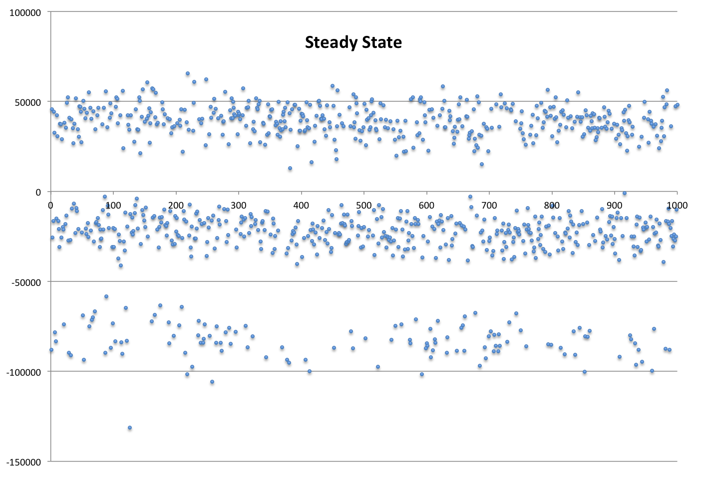
After sampling 1000 times, there are clearly 3 different groups. I don't know any reason why that is the case.
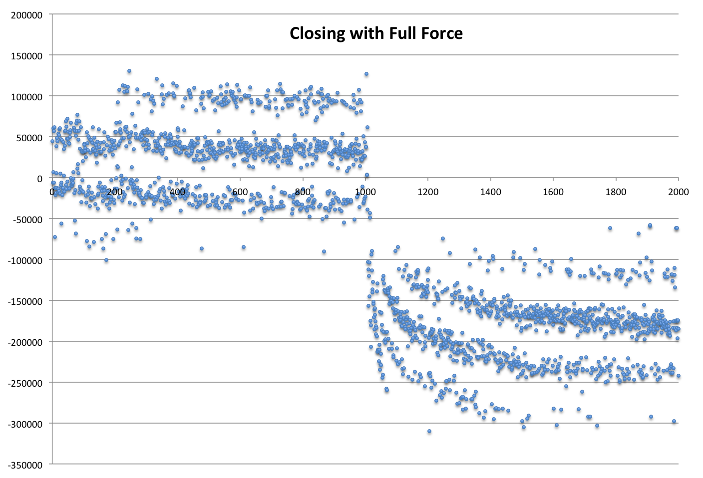
In this plot, I first held the sensor (with sorbothane covering) as it calibrated and for the first 200 or so points. Then I let the Robotiq lightly hold the sensor. At point 1000, the Robotiq closed as much as possible, with minimum force and speed settings. All of the groups of data moved together, until settling on the final force value. It's also interesting that there are seemingly 4 groups now.
I think I need to find a way to reconcile the groups, and not just base the reading on individual samples. I could average some number of points, or actually distinguish between the groups by some threshold. It looks like the groups maintain the distance between each other.
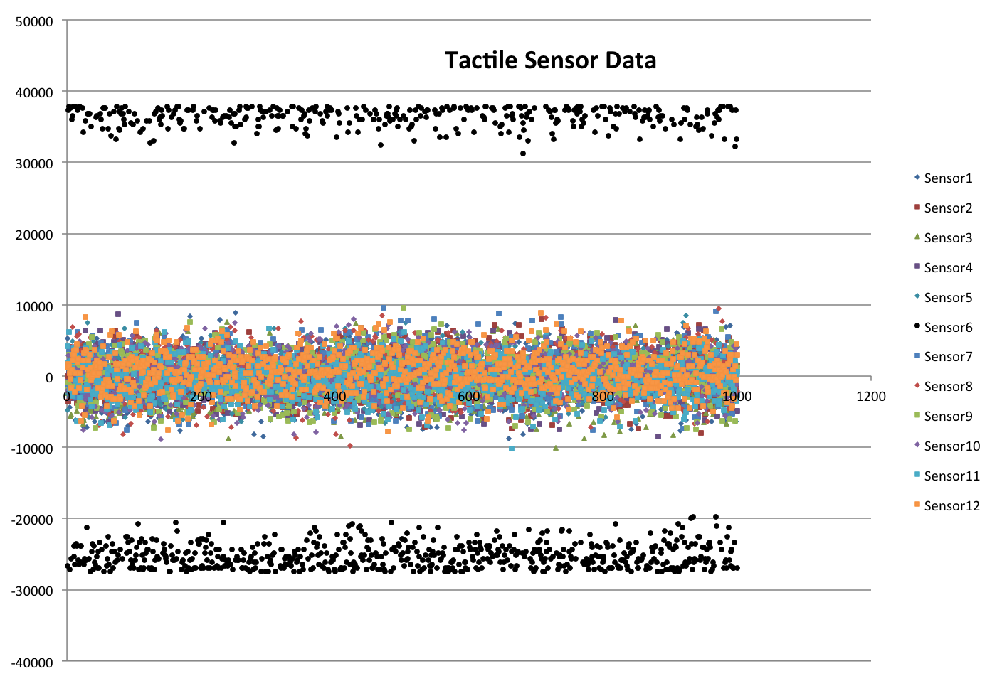
It looks like Sensor #6 is causing the problems:
8/14
Yesterday I wrote a script that can receive data from John's Tactile Sensors. The goal will be to demonstrate this sensor using the Robotiq hand to hold on to something and minimize the necessary grasp force. I'll try some preliminary experiments first where the hand will grab the sensor.
8/9
This is a plot that shows a little bit about how precisely the Robotiq hand can move. It shows the difference between encoder readings before and after sending an open/close command (task). It also shows the same over sending a stop command.
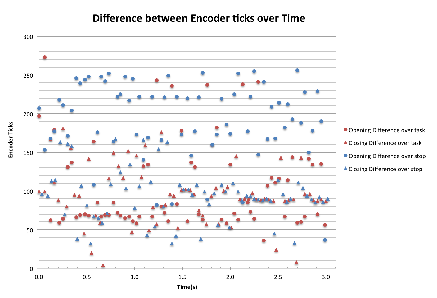
The vertical scatter shows the consistency of the timing. It looks like opening & closing are more consistent than stopping, and that opening commands are more consistent than closing. It is also worth noting that after sending a stop command while with hand is opening moves the encoder by the most. That is, the hand opens faster than closes, so it travels over more encoder ticks.
I haven't found information on the gearing of the hand so I don't know exactly how much motion corresponds with 1 encoder tick.
The next thing to do is to see how accurately I can tell the hand to stop when it reaches a certain value, and make fine adjustments. I'm doing this by successively opening, stopping, wait 0.5s, closing, stopping, wait 0.5s etc. That way the hand will settle from it's motion after each step. The goal is to find out if the position will drift with time, and how much will a springy object help to reduce backlash.
 |  |
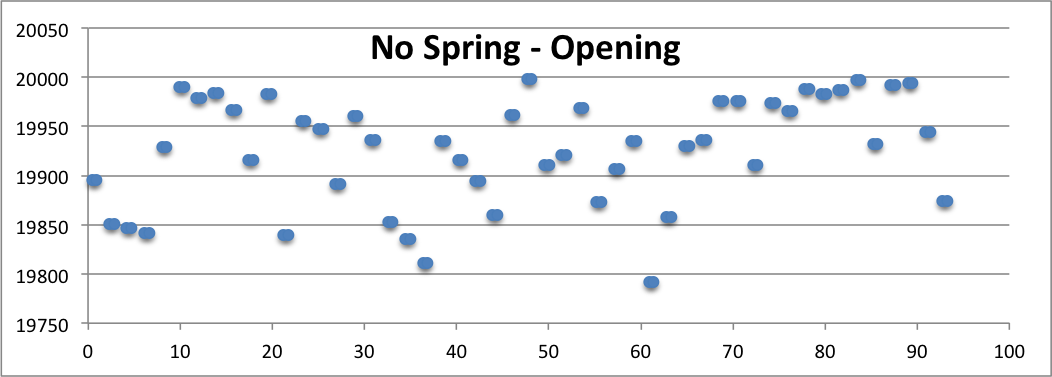 |  |
The vertical axis represents the encoder ticks. The hand was commanded to close after reaching 24000, so all values are over that value. Similarly, opening would stop after reaching 20000. These show that the rubber bands that I added did not have much of an impact on the accuracy of the motion. That means that the error must be coming from the communication.
8/8
I wrote a script to move the Robotiq by small amounts to test how precisely it can move. I've implemented it by sending an open/close command, followed by a certain delay, then a stop command. Using the lowest speed and force values, a delay of 1ms is the smallest recognizable step. Any steps smaller than that move by the same amount. Now I'm going to use the encoder data to find out more precisely how far is the minimum move.
8/7
Over the last few days I've been working more on the active filtering. The plan is to use a charge amplifier design because of the inherent capacitance of the sensor.
Separately, we want to demonstrate the abilities of the shear and normal sensors in performing a minimum power grasp. That is, the system will use the shear and normal components to estimate a coefficient of friction, so that the gripper does not grasp too tightly. We can either use the Robotiq hand, possibly ARM-H, or make a new simple opposing gripper.
- ARM-H is the least likely because of physical access to the hand as well as needing to re-setup that workflow. There could also be noise from the electrolaminate brakes that the existing sensors have trouble with.
- I'll try Robotiq first, to see if we can grasp gently and switch directions quickly. This will be a little trickier because there are only open, close, and stop commands for the fingers (as well as the grasp mode). I'll set the speed and force very low and see how sensitive it can be. THen we would need to interface the sensors into ROS probably, rather than rewrite Robotiq code.
- A custom hand would be a simple design but we would still have to make it. That could be controlled in a number of ways, either Arduino or the PICs that have been used for the sensors. In this case, the sensor pipeline could be the same, and then just extended to control the gripper.
8/1
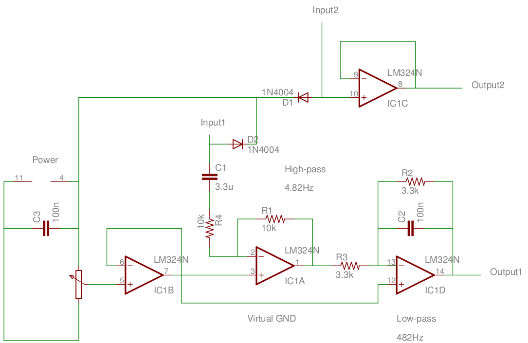
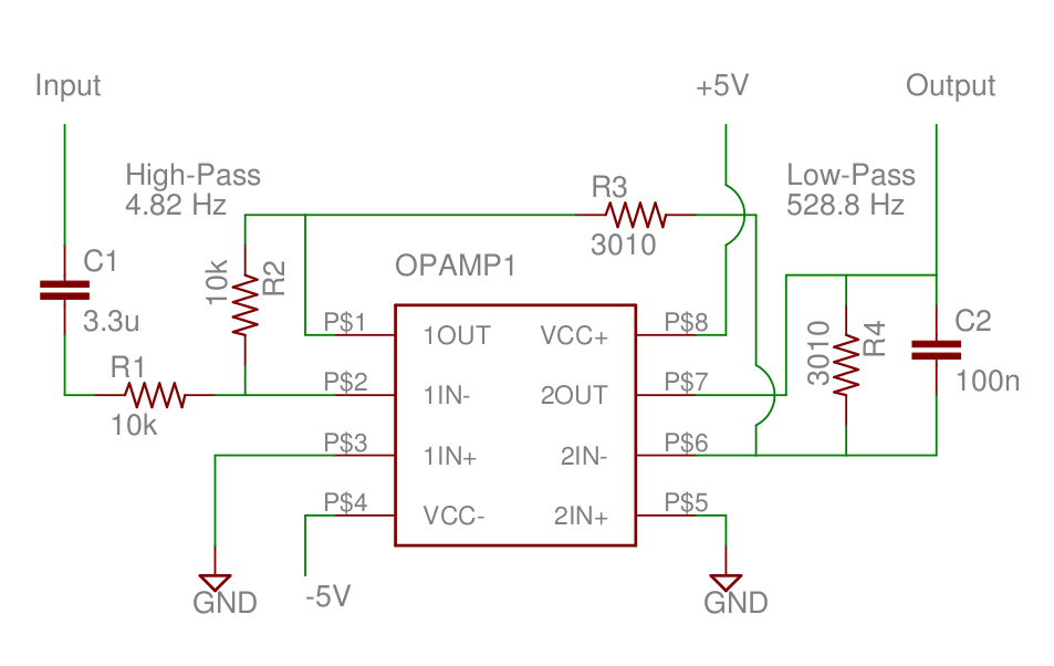
Working with Barrett, we tested the active filtering. I first tested the buffer, high-pass, and low-pass stages to confirm that they work. We noticed that the output signal was attenuated between the high- and low-pass filters, because the cutoff frequencies were so close to each other. Then to try with the PVDF we made a small buffer circuit to match the op-amps but without any gain or filtering. However, when we compared it to the band-pass filter, we didn't really get much signal at all. So far, it looks like it is because the PVDF has a low internal capacitance and high internal resistance. The internal capacitance is very small compared to the high-pass capacitor, so there is a very small gain.
 |  |
7/31
After talking to Barrett, I added the "Brake" command to the Adept serial program. It tells the arm to decelerate and come to a stop. I added that functionality into the Adept ROS package, as well as a small demo using the PVDF sensor connected to the Arduino. On a touch event, the Arm comes to a stop.
⚠ <iframe src="https://docs.google.com/a/stanford.edu/file/d/0B2QnaE33VpUhUUp3TDFaT1JUbFE/preview" width="640" height="385">⚠ </iframe>
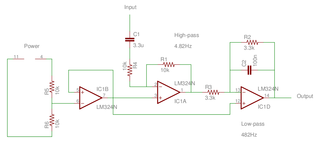
The next thing is to redo the active filter using Hannah's Op Amp. I also added a buffer to the front that will provide a 2.5V virtual ground.
7/30
I found an Op Amp and built a band pass filter for the PVDF sensors. The idea is to cut off low frequencies that could be from the table vibrating or the sensor itself moving. Next we will cut off high frequencies according to the Nyquist frequency for anti-aliasing.
Trying it out with the Arduino, I didn't find much appreciable difference. However, Hannah and I weren't able to get a signal on an oscilloscope either. Next time I'll try a different Op Amp that Hannah used in her classes that we know exactly how to use.
7/27
Today we hosted the barbecue! And then I learned more about passive and active filters from Alice. The plan is to have a filter for the PVDF sensors and also have better shielding to eliminate that 60Hz noise. Then I'll see the efficacy of the simple difference window calculations, and maybe how to improve that. Also back on the hardware side, it could be better to use a commercial ADC with a higher sampling rate than just the arduino's ADC, and then plug that into the arduino. Finally the demo idea for this is to have the Adept stop when a touch signal is received. However, it looks like I will have to add more code for the Adept itself, not just ROS, to accept this kind of "Brake" command. I'm not 100% sure though, because I might be able to just send a tool-offset command instead that sets the new coordinates equal to the original goal.
7/24
Now that I have the Arduino set up using Kessel, I can visualize the data better using ROS tools that didn't work in OS X. raw_data is the 10bit analog data from the sensor (0-1024), average is the moving average of the data over the last 100 points, and diff is the sum of the differences between raw_data and average over the last 10 points. I'm normalizing all of them to 0-1024, by subtracting 1024 from raw_data and average because they float high, and dividing diff by the window size, 10. In the first experiments I'm pressing with my finger, and in the next I use a piece of rubber attached to a stiff back.
 |  |
| Finger | Rubber |
In the above tests I press and then release. One reason for the variation from the rubber tests could be from difficulty in maintaining a constant pressure on the sensor. With my finger I have complete control, but I don't know exactly how much I am pressing with the rubber. The rubber is also much stickier so it caused the sensor to pull up a bit on release. The oscillation that I saw earlier is present in both, so it's not likely to be just from my heart beat.You can see that they have the same frequency, so they are likely from the same source.
 |  |
| Finger | Rubber |
In these tests, I pressed 4 times about 2 seconds apart and then had a sustained press followed by 3 presses about 1 second apart. You can see that with the rubber it is still possible to distinguish the different presses, but there is less control over the end so there is more noise as different parts of the rubber come into contact and release. In this case the stickiness also played a large role, as you can see by the noise at the end.
7/23
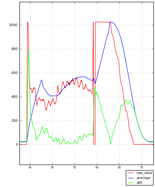
I have a better understanding of the purpose of the moving average now as a baseline to compare to. Setting it to 100 points is much smoother. I also implemented the difference window, which sums the absolute value of the difference between the signal and the average over a window. It produces sharp spikes on events. That window size will be dependent on the sampling frequency, the rubbery material used, and other factors. Maybe I can find a method on how to best tune all of the different parameters to produce a clear signal. Another idea for this window is to see if we can differentiate contact from release events, and also if absolute value or RMS is better.
 |  |
In the 1st plot of the difference window values you can notice how after pressing on the sensor, the value falls eventually because the PVDF settles and also the average value catches up with the sensor data. Then on release there is another spike because of the absolute value. In the 3 short presses you an see how even when using this difference window the value steadily rises, to the point where the drop from the 3rd touch is not much lower than the initial peak. This means that the parameters need to be tuned better to catch these smaller signals.
The 2nd plot shows a strange periodic nature to the signal, when no one is touching the sensor. This also happens sometimes after a sustained press. I'm not sure what is the cause at all, and I'm not sure about the best way to deal with it. Something else that may happen is the value doesn't always fall to 0, it sticks to 427. I'll see if these have to do with my math.
I found a ROS package that lets the Arduino publish ROS messages directly over a serial connection. This could be useful if the Arduino needs to do more complicated tasks like respond directly to information from the hand, but I don't think it's worthwhile to add extra features that probably aren't necessary. Anyways in that case the bridge node with the Arduino could easily pass along the message over the Serial connection. I also set up the arduino environment on Kessel so that it can receive the Serial data.
7/22
Today I changed the Arduino code to run on timer interrupts. That way I can get data from the sensors at a precise rate. I'm using 1kHz for now. The other idea is continuing the signal processing on the arduino. I have a fading memory average, where the last n points are averaged to reduce the differences between points close to each other. Here are some visualizations of the data from touching the sensor repeatedly (approximately 1Hz):
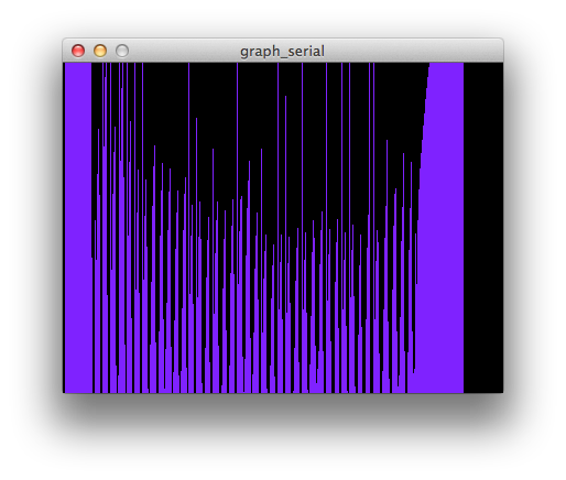 | 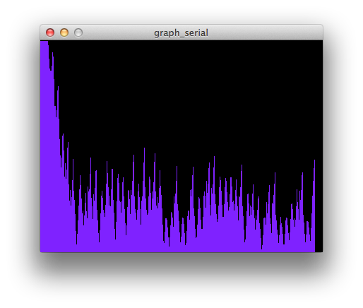 |  |
| No filters | 5-pt Average | 10-pt Average |
The average is successful in flattening the output. However, 10 points seems to be the limit of usefullness because beyond that pointthe peaks may be too small.
7/21
PVDF Sensors
I started with reading directly into the ADC of the arduino, and I can visualize that using Processing to create a graph. I'm using the 2.5" sensors.
- floats high but it is very noisy so it drops and rises
- Touching drops the value, but it takes longer than expected to rise back up.
- Because of that you wouldn't be able to use it for many touches in a row because they would all be low.
- One mystery is that i can greatly reduce the values by covering the sensor with my hands (not touching)
- Solved! PVDF is also a temperature sensor, so the heat from my hand is causing a change
- Different reference voltages:
- 1.1V (INTERNAL) drops sharply from any input, and also rises quickly again
- 5V (DEFAULT) floats in the bottom-middle, but rises to the top after being touched and then sinks again
- 0V (EXTERNAL) doesn't change with touch
- 3.3V (EXTERNAL) floats in the top-middle, acts like 5V but at a higher rest rate
- so 1.1V is the best option
Unfortunately I couldn't get the Arduino software to run on Kessel, but I was able to do everything from my mac. Other than those experiments I wrote a ROS stack to publish the serial information out for other tasks.
Next steps:
- Compensate for ambient temperature using another sensor (it would run faster directly on the Arduino)
- Publish a bool for a touch based on a threshold difference instead of an absolute value.
- Try out other sensors
7/20
7/19
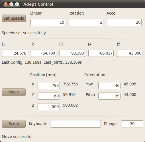
Today I made the Adept Dashboard run on my own laptop in OS X. But I haven't gotten the ROS networking set up done, so it isn't perfect yet. The main reason I wanted to do this is that I really prefer my own laptop for writing code because Kessel's screen is stretched and the good editor doesn't run on the older version of linux.
Instead of spending more time on this I'm going to work on getting the Robotiq hand working on Kessel, and then I will try some maneuvers with the Adept and Robotiq. I want to know what kinds of control are useful for performing experiments with the sensors, so I need to try out my keyboard interface first. Also I will keep seeing if I can make it more continuous and less jerky. Perhaps joint commands?
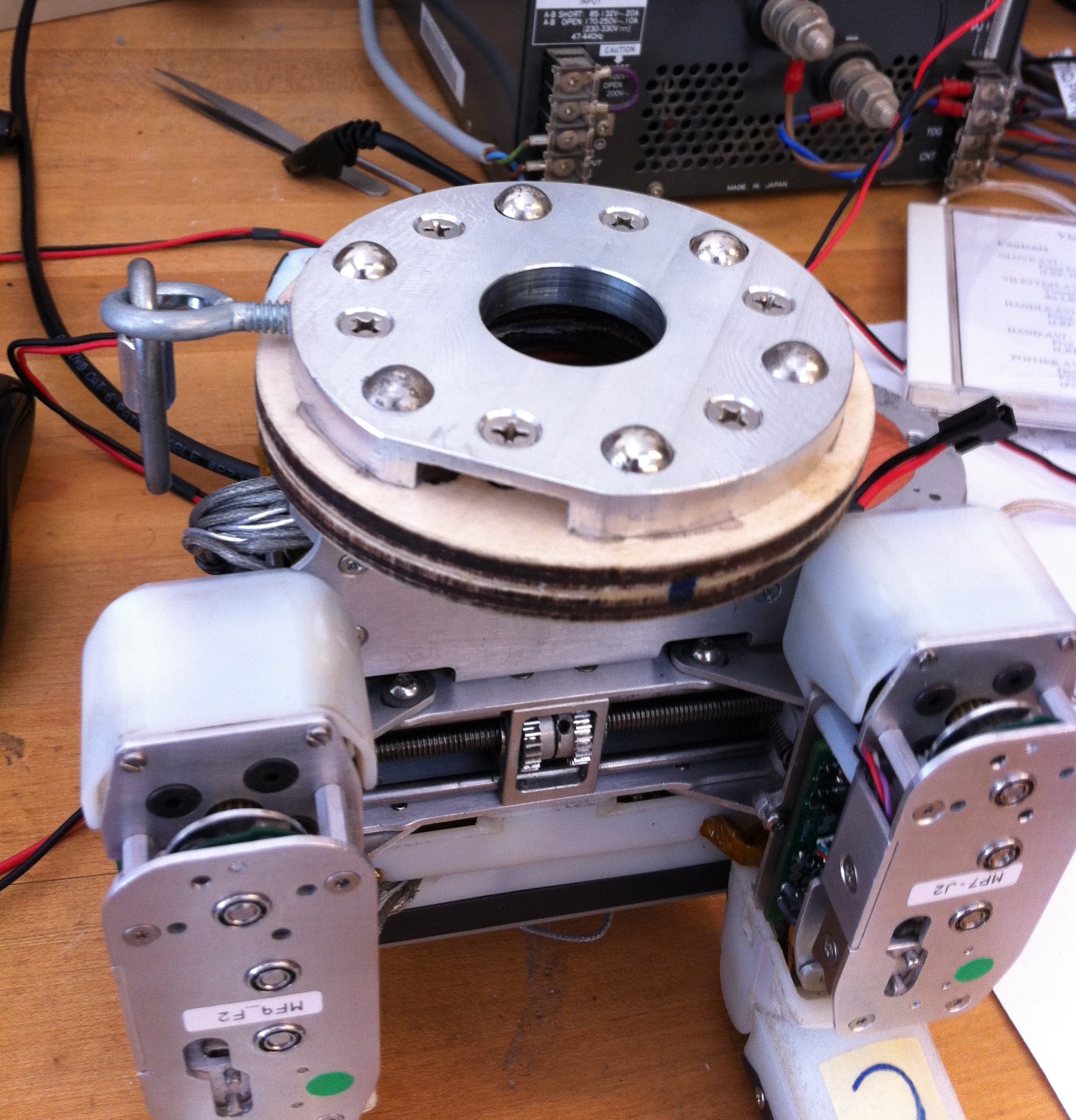
I made the Robotiq hand work by fixing some errors that come with python versions, but then the USB to Serial dongle repeatedly lost the signal. We threw away that one and by using a new one I could connect it to the Adept and run it properly. The Adept cannot rotate a hand at the wrist so to speak (there is no roll, only yaw and pitch) so the placement of the magnets on the hand in the indentations on the arm is important to set the roll to a constant. There are 6 magnets arranged in a circle, so the roll can be set at increments of 60 degrees.
The keyboard control wasn't ideal, for the same reasons I saw earlier. It's slow because of the limit on communication speed with the adept over serial. Also because I am just sending commands to move to a new position each time, the arm cannot accelerate because each command is distinct. Maybe I can use joint commands, or just have a longer distance step mode. I will also update the numbers displayed in the original move command area to reflect the keyboard commands.
7/18
Setting up the Kessel computer to run the Adept, Robotiq, and ARM_H using ROS because the small Cappuccino machine we were using before actually belongs to meka. So far I have set up Ubuntu 10.04 and installed ROS C-Turtle, which are both the same versions that were installed on Cappuccino. The next step is to make sure that we can run the Adept, Robotiq, and ARM_H. The M3 bridge software for ARM_H might be tough to set up, and we don't have that hand at the moment anyways, so I'll begin with the others.
Today I implemented the Plunge feature, so that the Adept can grasp from any angle. We know the position and orientation of the hand, and so by providing a distance to plunge we can make a vector for the Adept to follow. We do not need to calculate the inverse kinematics because the Adept will do that if we give it the goal coordinates.
To run the adept I had to change a bit of python syntax because it runs 2.6 not 2.7.
Implement gamepad/KORG control? joint move control in keyboard?
7/17
How does underactuation and the sensor suite affect what can be grasped? What can we grasp better because of those things? I think the difference will come in grasping very delicate things that move: the sensing allows us to not push too hard on the object, and it can move to adapt to a moving object. So then either all of the sensor data is communicated back to the controller in an intelligent way, or the hand itself can change its behavior on the fly. But the challenge with that is that the operator can feel like they are losing control over the hand, or it may feel extremely loose and passive.
So what tests need to be done to verify this and find out more? I think holding on to soft materials delicately and varying the amount of sensor-based compliance could tell us how important that feature is. Perhaps performing a task like moving delicate objects around or carefully screwing in something?
7/16
Last week and today I have been working on the Adept Arm. I am adding some features to the original dashboard, such as workspace boundaries, scripted motions, and keyboard control. Keyboard control is not as smooth as jogging a CNC machine because of the slow serial interface speed. In fact, if you send commands too fast, it "overloads" the connection and the Adept halts.
7/10
Today I assembled the adapter for the ARM-H and Adpet Arm. It consists of 2 pieces of 3/8" plywood, with 6 holes for the Adept side and 4 for the ARM-H side that go all the way through both pieces. However, the Adept side has 6 hexagonal holes to hold nuts, and the ARM-H side has wider holes for the head of screws. That way after gluing the pieces together, the nuts for the Adept are trapped as well as the heads of the screws for the ARM-H.
7/9
ARM-H to Adept mount
Currently, there is a way to mount the blue Robotiq hand onto the Adept using two special plates which hold the hand on by magnets. Earlier I drew an adapter for the ARM-H hand to that mount system. Today I lasercut the 2 pieces of the adapter from plywood, and I will assemble it tomorrow.
Some potential things to work on for the Adept:
- define a workspace (probably on the ROS side) that is a safe area to work in
- create a roslaunch file so that it is easier to start everything
- configure the tool zero for the arm-h hand. Probably the center of the palm, or even somewhere within its grasp
AR.Drone
It looks like the switch to sdk 2.0 within the ROS package is complete, it compiles without errors. However, it segfaults because of the video thread. Commenting those areas out, the program runs but does not communicate with the drone still. There could be differences in the implementation of the video thread between versions of the sdk (USING_SDK_1_7), so I should read sdk 2.0 documentation. I also could have commented out more than I should have: the video thread could be necessary for all communication. There is also an initialization of the IP address of the Drone as "NULL" on the ROS side but it might automatically become set to 192.168.1.1.
A completely different approach is to just use the SDK, because what we really want is good teleoperation and the ability to change system variables like euler_angle_max. While trying that out I got video feed to work from both cameras by downgrading the firmware of the drone to 1.4.6 and using SDK 2.0.
7/3
Compiling my results from playing with the AR.Drone, which has the newest firmware:
In VM - Ubuntu 10.10:
- I don't think there are any issues with using the VM, because I have communicated with the drone
- I have ROS installed here so I can test ardrone_brown
"Navigation" example in SDK version 1.7:
- Builds with no errors
- Navdata timeout on port 5554, and the whole process gets stuck
"Navigation" example in SDK version 2.0:
- errors building a part of the video code, but I have fixed those now
- No errors anymore but still no video
- Also no gyro data, it stays at 0
- Navdata timeout on port 5554, but the whole process doesn't halt
- Sending some data works, the drone acknowledges pressing some control buttons
- Not sure about teleop - I will bring my USB gamepad to try it out
ardrone_brown
- need to find out what version of sdk this uses
- builds correctly
- Has errors enabling multicast, which allows multiple devices to connect to the Drone.
- Navdata timeout on port 5554, and the whole process gets stuck, like SDK 1.7
mkoval-ardrone_brown
- updated version from the original to SDK 1.5
- not building correctly yet
nlele-ardrone_brown
- I will try to update it to SDK 2.0
On Mynock - Ubuntu 11.10
- This is a slow computer but it is not a VM, so any issues from virtualization won't be present
"Navigation" example in SDK version 2.0
- stuck "Getting AR.Drone version"
- same error for all of the test programs
7/2
AR.Drone
It's hard to tell if there is still a networking problem, because using the SDK version 2.0 for AR.Drone I was able to run a sample program that displays all of the information from the drone. However there is no video yet for that program. A few things online suggested that the problem may be from multicasting, which allows multiple devices to connect to a drone. I still have the same errors from the ROS package, ardrone_brown, so one way to fix it may be to switch it over to the SDK 2.0.
Hands
Right now for the hand projects we want to try picking up many different objects. So I think I'll start looking up how to control the adept arm and a hand in conjunction to do some simple tasks. Also something else for farther in the future is to have a hand controller that can adapt its grip to the data received from its sensors, so that it can be more delicate or secure as needed.
6/29
Well it took a lot of time and multiple VMs but I finally got a version of ROS running properly in my Ubuntu Virtual Machine. But I think I've learned more about the structure of ROS and its build system when I saw the problems. So the next step is to actually interface with the AR.Drone. What you need to do is to connect to the WiFI network that it creates and then listen and send on certain ports. So I have scripts to connect and disconnect from OS X, but the problem is that Ubuntu VM can't listen properly on the specified ports. I have tried Port Forwarding the NAT connection but it hasn't worked yet. One option is to move everything into Linux by exposing the AirPort directly. The other option is that there is a problem with the program that I am running, which I will also check.
6/28
More on the Parrot AR.Drone. I've found a document (ARDrone_SDK_1_7_Developer_Guide.pdf) that gives great details about the UAVs features. Potentially promising is the ability to change "altitude limit, yaw speed limit, vertical speed limit, AR.Drone tilit angle limit, host tilt angle limit." I don't know about host tilt angle, (maybe iPhone tilt?) but the other tilt will be useful if we want to pitch up sharply without an error. I don't think these are exposed in ardrone_brown, however, so I will see how to add them.
6/27
Today a representative from SIMPACK came to the lab and gave us a bunch of documentation and training tools. Interesting features will be .subvar files, which is almost exactly what I was looking for earlier. In this file you can edit the values of SubVars easily, and import them into a model. I haven't seen an API yet for the scripting interface in the model view, but my new understanding is that it is meant to automate running time-integration jobs. So we could have it run several jobs using different SubVar files. Flexible bodies are currently disabled but we will get another license to use that has that capability. It might not be exactly what we want, though, because it is meant for high stiffness and low deformation materials like steel, and our rubbery materials might not be emulated as well.
6/26
Parrot AR.Drone
I started looking into controlling the Parrot AR.Drone which might be easier to perch than an airplane. One great thing about it is that it balances itself automatically, so we don't have to worry about that at all. There are SDKs available for programming the actions of the drone directly from either Linux or Windows, but I think for our purposes we can easily use this ROS repository from Brown University: http://code.google.com/p/brown-ros-pkg/wiki/ardrone_brown It basically takes out the step of interfacing with the SDK, so we can just publish Twist messages on some simple topics to get it to move around nicely. There is also a keyboard teleop script (drone_teleop) so we should be able to start playing with it pretty quickly.
One potential issue is that the drone gives a big error and halts if the drone flips over, which might happen while perching. (http://ardrone.parrot.com/parrot-ar-drone/usa/support/faq see "TOO MUCH ANGLE EMERGENCY")
SIMPACK
We can get a better friction model in SIMPACK, but we can at least use springs and dampers as a rough estimation. To use the software as a tool we need to be able to change parameters and see how the results change. There are a few ways to do this:
- python to generate the .spck file used to describe the entire SIMPACK model, and change key values - This is the same thing that Dan is doing now using his other simulator.
- QSA (basically javascript) scripting during the Pre-Processor - The big problem here is that there is no API or help that I can find at all. If I can find a way to change SubVars within the program using a script then we would be set.
- QSA scripting during the Post-Processor - This is a little bit more described, but my understanding so far is that you cannot change SubVars or anything in the model from the Post-Processor. I think this scripting is for creating GUIs mostly.
- MATLAB + SIMULINK - there is a way to communicate between SIMULINK and SIMPACK, but the documentation I have seen only refers to control systems and high-level interfaces. I haven't seen any exposure of SubVars here either.
- User Routines - Unfortunately these are in Fortran and very dense. I don't think there is an interactive way to edit them, I think you would have to edit it like the .spck file.
6/25
I've started looking at the codebase for the ARM-H hand. There is code for communicating back and forth with the hand through ROS, but there are still some aspects to work on so that testing for fingertips is easier:
- auto-homing/auto-calibration, so that startup is easier, especially for fingers.
- motion-planner that coordinates braking to move to any position, despite underactuation
- using touch-sensor data, eg. close until pressing lightly
Some Motion Planning ideas:
I like the idea of using a sequence of pre-described maneuvers to approach the target configuration because it lets us use our mechanical understanding of the hand. It's very easy to imagine the motions required by our own hands, so we can describe some good maneuvers easily.
finger maneuvers:
- brake 2 joints, move cable until the remaining joint moves to position.
- brake 1 joints, move cable until the other 2 joints move to position.
- brake 0 joints, move cable until all 3 joints move to position.
Then we can use these maneuvers to build some simple planners:
distal-priority finger motion planner:
difference-priority finger motion planner:
specific grasp planner - move 2 distal joints first, then approach with the first one
We know the kinematics of the hand so one approach to a planner could use this knowledge to make joints move together in a faster way. I'll look into this aspect next. I also will look more into specifics of implementation.
6/20-6/22
I've continued to work on SIMPACK as well as an older piece of software called Working Model 2D. Now in order to understand the frictin modelling in these programs I first need to learn a bit more about friction, largely because these programs use several parameters and several different ways of modelling friction. So I'm going to read more and play around with the software to understand friction, but I'll also make a little prototype to test with a simple sliding block or simple rotation. The main thing is that I don't have a sense of what numbers are reasonable for all of the different parameters.
Things to find out: Is SIMPACK using the penalty method for collision detection? Use simple damping for joints, and check if it's the same as a large eps in the viscous joint.
Arm-H geometry: phalanx lengths: 1:57mm, 2: 40mm, 3: 28mm. pulley radii: 12.5mm, 12.5 * 0.7 = 8.75mm, then 12.5 * 0.7 * 0.42 = 3.67500 0.1 Nm/rad spring stiffness. damping is some fraction of it. motor can give 30-50N. 25mm diameter, tapered a little bit.
6/19
Still working on SIMPACK, which can simulate forces and torques on different bodies connected by joints. I've been going through a tutorial showing a triple pendulum, which is pretty relevant to simulating fingers, which is what motivated learning about simulation software in the first place. I learned about the post-processor as well, which can make some nice looking plots and animations from a completed simulation. SIMPACK organizes everything by having each joint possessed by exactly one body. I'll have to see how more complicated joints work. Also damping and using more complicated models is necessary in order to model the real things.
I also started learning about Arm-H and how to control it. There is a whole lot of ROS python already written for it so the next steps are for integrating touch sensor data and joint data into a good motion planner. There is also a project for improving the teleoperation of the hand.
6/18
Got set up in the lab first. We went to a meeting with the CS department people on the Red Sea Robot Project, and another one about biomimetics work in Seoul. I started learning the simulation software SIMPACK, more on that later.