category: SummerBlogs
Research progress updates
Final updates
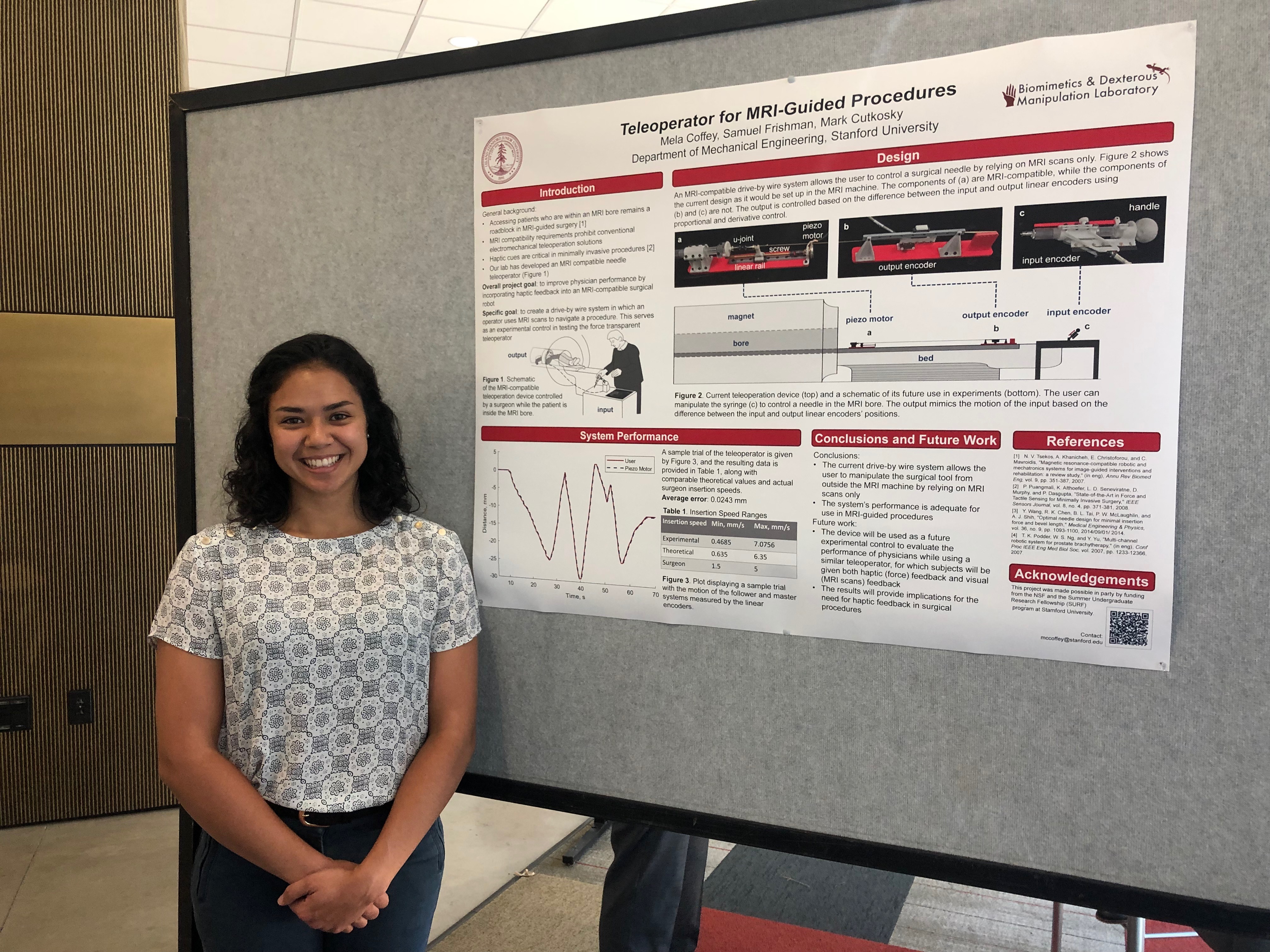
Mela at the SURF poster session
I finished up the SURF program and my time in the lab last Thursday, August 15 with a final poster session. I'm very happy with all I accomplished throughout the past eight weeks in the BDML. I finished the experimental control, the teleoperative surgical device without haptic/force feedback, which will be used in future experiments to compare against a similar device with force feedback. I also finished the phantom box the experiments and circuitry for the control system. I wish I could be there to help with experiments and to see the results of the force feedback system, but Sam agreed to keep me updated.
I'm so grateful for such a valuable experience in the lab, and I would like to thank Mark, Sam, and the entire BDML crew for opening their lab doors for me this summer! I'll definitely be applying to the Stanford Mechanical Engineering graduate program this fall, and I hope to see everyone again soon.
August 6-7
Within the past couple days, I've reprinted some parts that needed some slight editing and replaced those in the assembly. Then I collected some position data from the linear encoders so I could see how much the motion of the two sides vary, such as how much the follower side lags behind the user. Aside from that, I've been working on my poster, and I'll have a draft of that tomorrow.
August 5
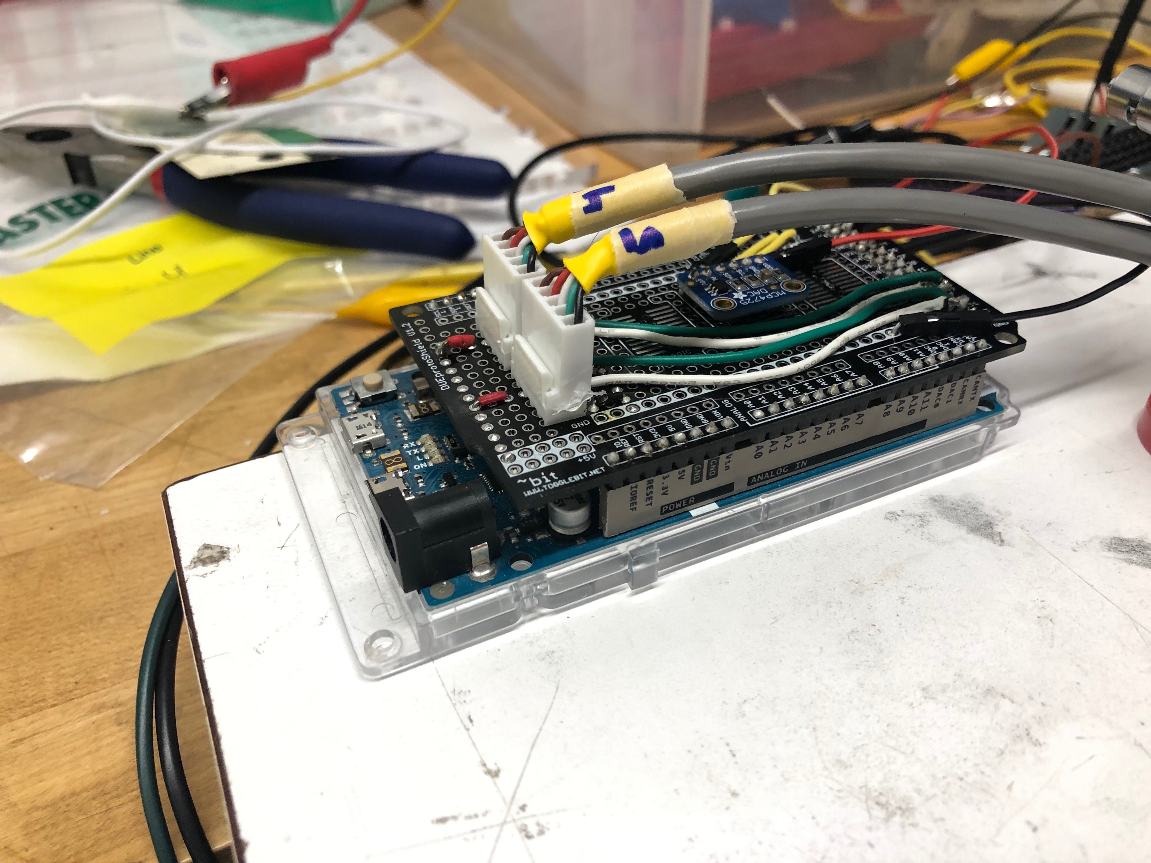
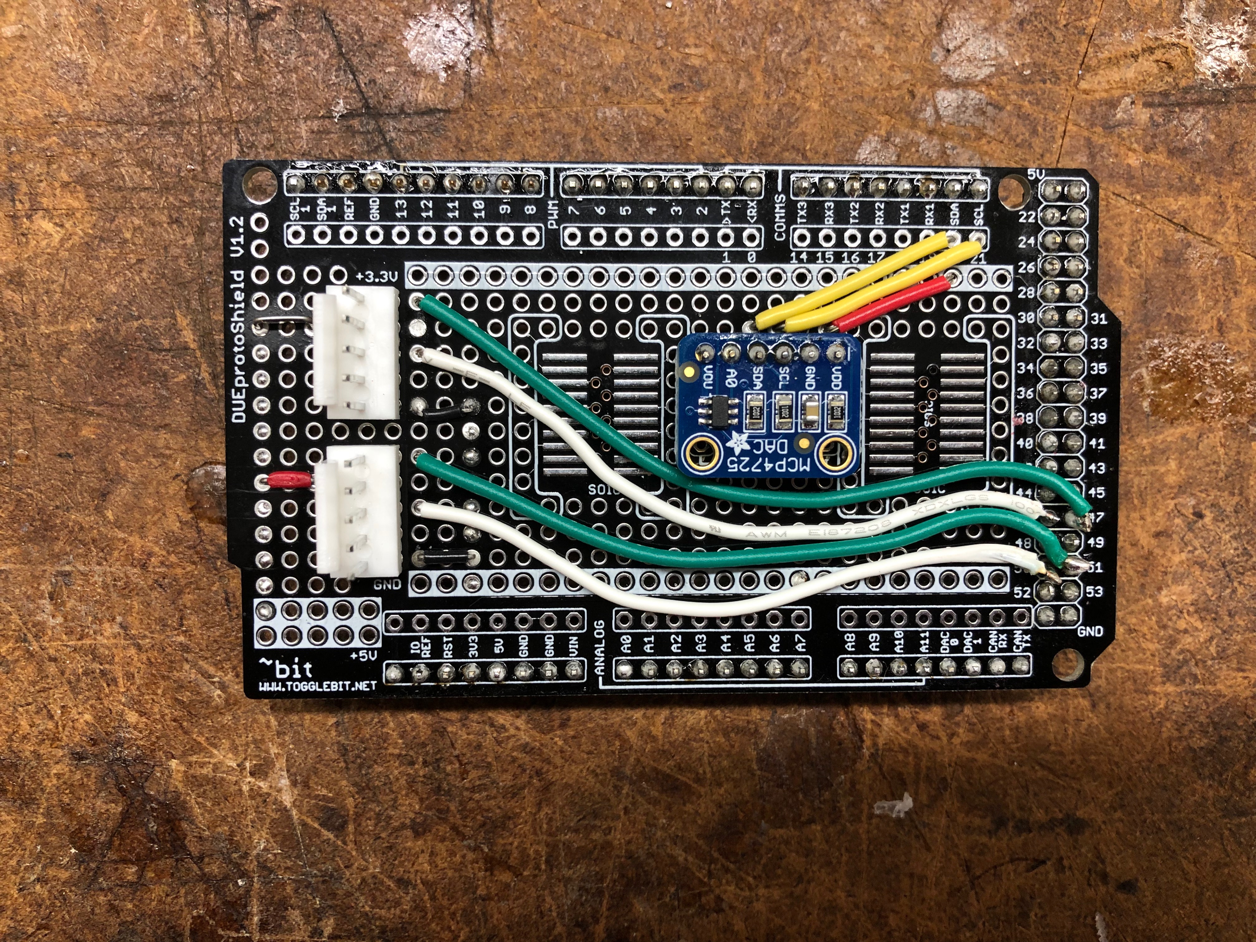
Today, after SURF activities, I began planning out my poster for the poster session next Thursday. I have an idea of what I'll have on it and the general layout. I also worked the wiring of the piezo system a bit more. We want to adjust the lengths of the wires accordingly for the experiment, since the power supply and motor driver have to be far from the rest of the system because of its MR-incompatibility. I soldered some wires to an audio cable, which will connect to the DC power supplies, and we ordered some molex connectors to connect the motor driver and Arduino Due. Doing this will allow for simple quick-release mechanisms.
August 2
I mostly worked on my portion of the Medical Robotics Corner presentation we gave in the lab meeting today. We took some last minute data for the piezo system, and the computers were having some issues with Excel - we ended up using MATLAB - so this took some time. After the lab meeting, we (the lab) all went to Rob's poster presentation for the Ignite program.
August 1
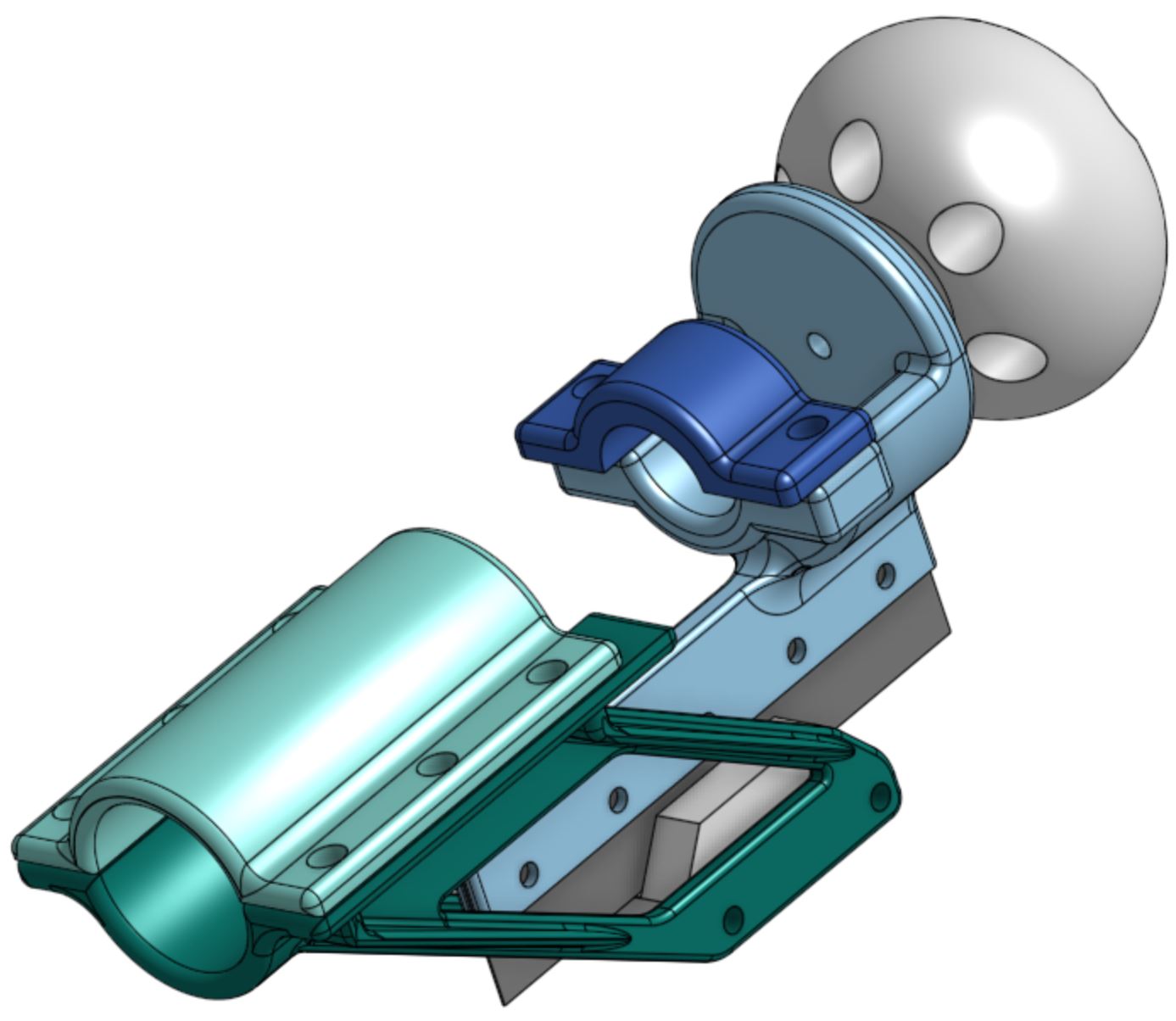
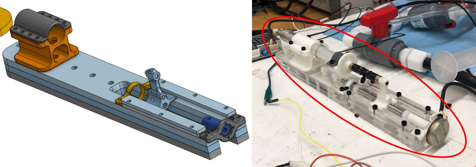
This morning I went with Sam to the Richard M. Lucas Center for Imaging to test out the phantoms in the MRI machine, and also familiarize ourselves with the system. I was excited to see the various images of the phantom and see how the experiments for the device I've been working on will play out! In addition, the challenges of adding multiple degrees of freedom to an MR-compatible surgical robot became more clear. Because the machine images in planes of three different axes, and at a slow rate of 4 images per second (the fastest rate), capturing images of a needle in a multi degree-of-freedom (DOF) system would mean that the orientation of the axes would have to change in order for the image to follow the needle. Adding more DOFs will be the next step of this project, but for now we are analyzing one DOF to determine whether haptic/force feedback will improve user performance for MR procedures.
After we got back to the lab, we (the medical devices corner) had our weekly meeting with Mark to discuss weekly updates - I'll be helping to write the NSF annual report, which should be a good experience.
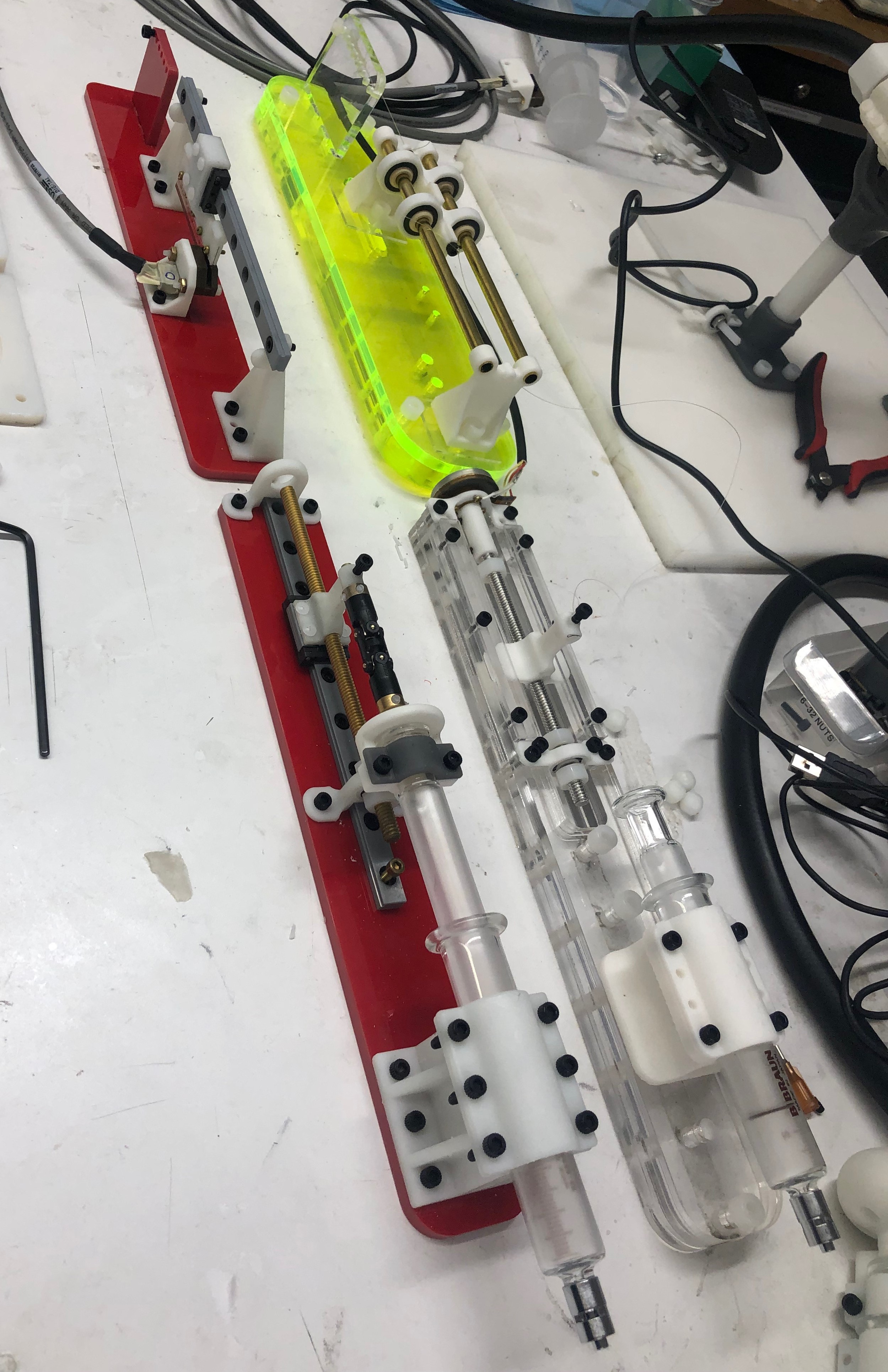
Then Sam and I tested out the new system I've been working on all summer, including the new hardware and cleaned-up circuitry. The system worked great! It runs much more smoothly now that we've incorporated the linear rail. There are of course a few small things we want to improve before using this in the experiment, but overall the testing was a success! Here is a video of the updated control system. In the video, I'm controlling the user side, which, for experiments, will be mounted at an angle to be more comfortable for the user. Directly to the right of my hand is the piezo side, which will be in the MRI bore controlling the needle. The string attached to it is pulling the encoder to measure the motion of the follower side.
July 31
Finished piezo motor circuit
Today I finished the circuit for the piezo motor. I also finished assembling the follower system, which included preparing and attaching the linear encoder strip, attaching the motor, and tying the string between the two ends of the follower system. The piezo side will be in the MRI bore pulling the encoder side, which will be outside the MRI bore because this side contains parts that are not MR-compatible.
July 30
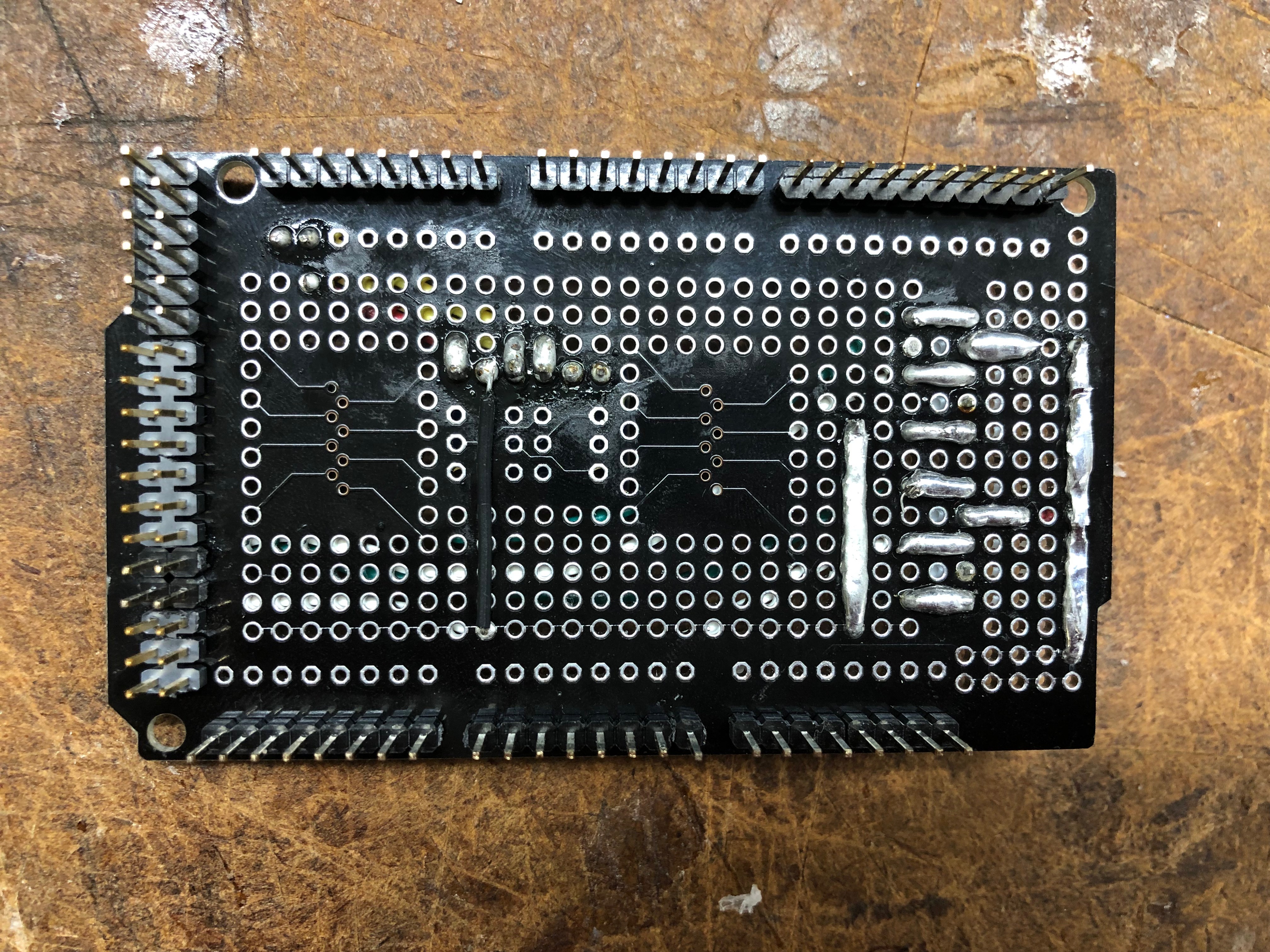
Underside of protoshield showing solder lines
Piezo motor circuit
I spent my time in the lab today soldering the piezo circuit, although I had to leave for the majority of the day for an SAP tour with the SURF program. I still finished almost the entire circuit, which took me some time, since this was my first time soldering on a protoshield. I soldered some things in an incorrect order, so I had to desolder and try again. I've attached a picture of the soldering lines technique I mentioned in my last blog post, and those can be seen by the thick silver lines. I still have to solder the male header jumper wires to the board, which will be connected to the power supply. After I finish the circuit, though, I can start testing out the entire follower/control system!
July 29
After my SURF activities today, I met Sam and Ali at the Falk Cardiovascular Research Center in the med school. I watched them collect data on their mitral annulus device in the lab's heart simulator, which was really cool to see! They were collecting video data to measure the deformation of the annulus.
When we got back to the lab, we had to do a bit of searching through the mail room to find the protoshields that were delivered over the weekend, but we eventually found them. Then I practiced a new soldering technique which I'll be using for the official circuit. Rather than using jumper wires for connections, I'll be soldering lines along the protoshield to create some of the connections in the circuit, since the holes of the protoshield aren't interconnected like a breadboard. I'm hoping that this technique will help keep the circuit tidy without the overlapping of jumper wires. I'll finish soldering the circuit tomorrow, now that I have the technique down, and I'll be sure to include pictures.
July 26
Fully assembled user syringe, excluding the encoder strip
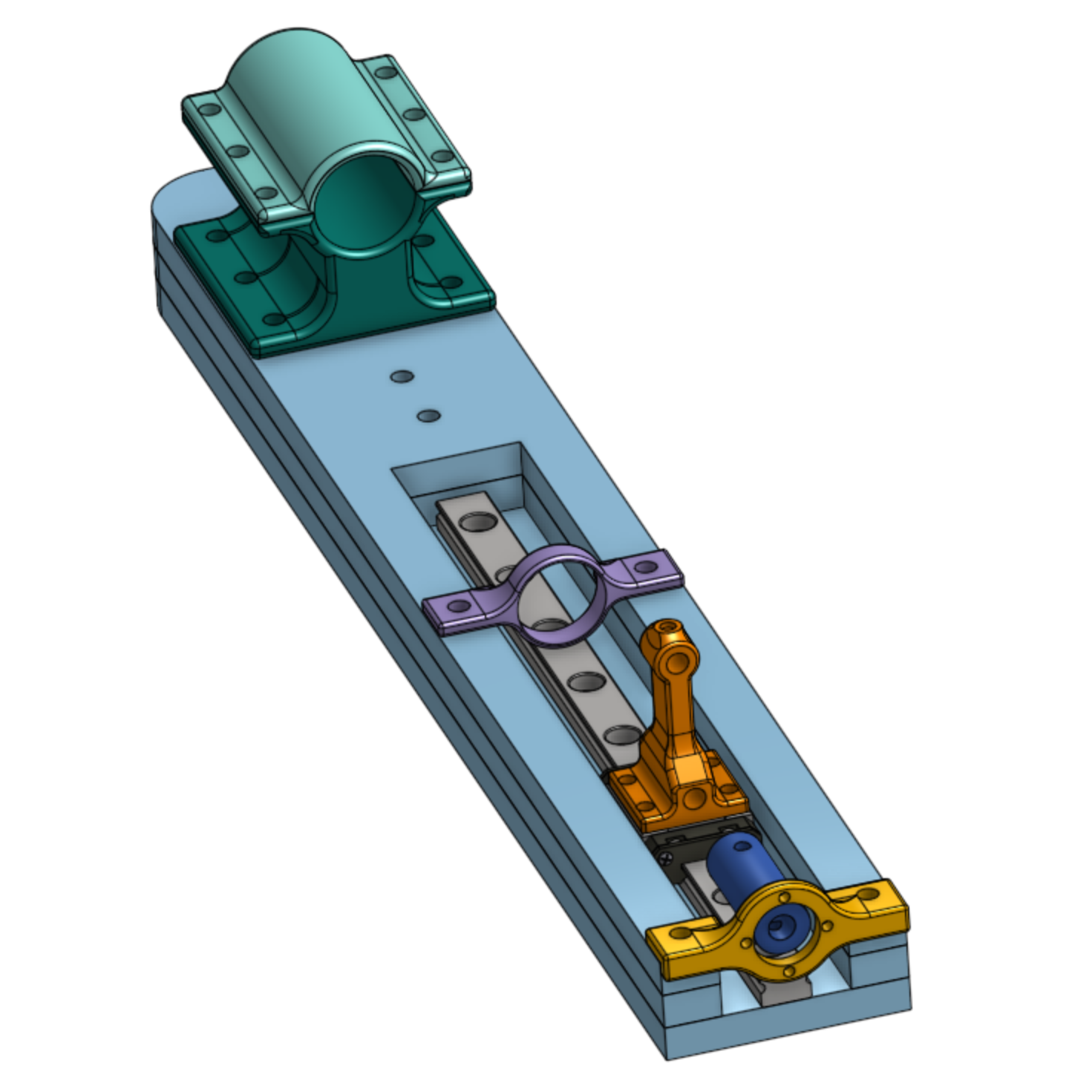
I didn't get too much done in the lab today since I was at a Google tour until 2:00 with the SURF program. When I got back to the lab, though, I pulled the user parts from the 3D printer, attended the weekly lab meeting, and finished assembling the user side of the system, minus the encoder strip. The user side is designed such that the parts can be attached to the user syringe only, while the encoder still measures the movement of the syringe. The thin red strip of acrylic is pinned to the syringe end and slides between two ball bearings on the other end to prevent the rotation of the syringe end, and the encoder strip can move smoothly through the encoder housing.
July 25
The new follower system (red) next to the previous system (clear)
Today I finished assembling both the phantom boxes and the follower side. After I clean up the circuitry using the protoshields, I'll test out how the new system works. I did some planning today for how I'll manage the wires so that once the protoshields are delivered, I'll be ready to solder right away.
I also edited the user side of the system today. It took a while to finish this because OnShape crashed when I was working in one of my part studios, so I had to contact support. Once it was working again, though, I was able to make edits and start the 3D printing of those parts. We're going to increase the length of the encoder strip to increase the range of distance that can be read by the encoder. In addition, I added a simple beam mechanism which prevents the user from rotating the handle of the syringe and potentially damaging the encoder.
July 24
This morning I pulled the rest of the 3D printed parts I needed from the printer and cured those. Then I went to Room 36 to laser cut a couple pieces I mis-cut yesterday. From there, I could tap the remaining parts and get to finishing the assembly of the follower side. We ran out of the screws we're using for assembly, so we had to order more of those, but aside from those screws we still need, the follower side is done!
The user side is also close to being done. I attempted to assemble the user side for the first time today and noticed that the encoder, given its position, may not be able to read the full range of position of the syringe. So I'll have to edit that tomorrow and reprint the part that holds the encoder.
July 23
I got the parts from the 3D printer this morning and put those through the wash and the oven to fully cure. However, one of the thinner, weaker parts warped in the oven, and so we're going to reprint that with an added rib for support. It took a while to completely clean off the build plate of the 3D printer, so that took up most of my morning. Once I finished, though, I tapped those new parts and could start assembling the follower side of the system.
I also went to Room 36 today to laser cut some more phantom boxes, since the current design works perfectly! Then I came back to the lab and started assembling those as well.
July 22
I came to the lab this morning after some SURF activities and worked on making the parts of the user syringe even lighter by shaving off some of the 3D printed parts that didn't need to be so large.
I then went to Room 36 to laser cut the updated version of the acrylic plates on the follower side of the system. When I came back, I tapped the acrylic and assembled what I could of the follower side - we hadn't printed the rest of the follower parts, but we started those prints today so we can add those to the assembly tomorrow.
Finally, I thought about how we might clean up the circuitry of the whole system, since there are currently a lot of wires, and the circuit is pretty confusing. I ended up ordering a couple protoshields designed for the Arduino Due. This way, we can stack the protoshield on top of the Arduino board, and all of the components of the circuit can be soldered to the protoshield without having to use an external breadboard, and the circuit will be much cleaner. These boards should be in by Friday.
July 18
Updated version of the follower system
Updated version of the phantom box
Today I worked on and finished up the follower side of the system, and those parts will be ready for 3D printing and laser cutting tomorrow.
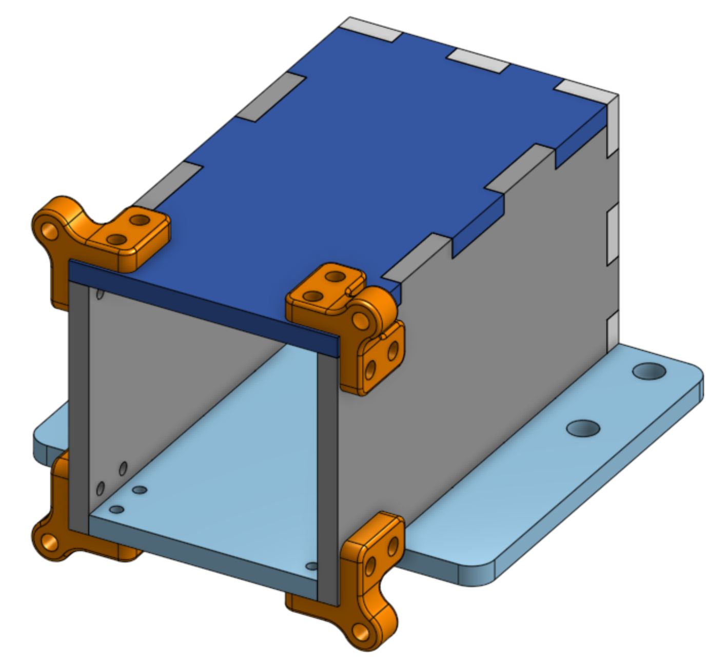
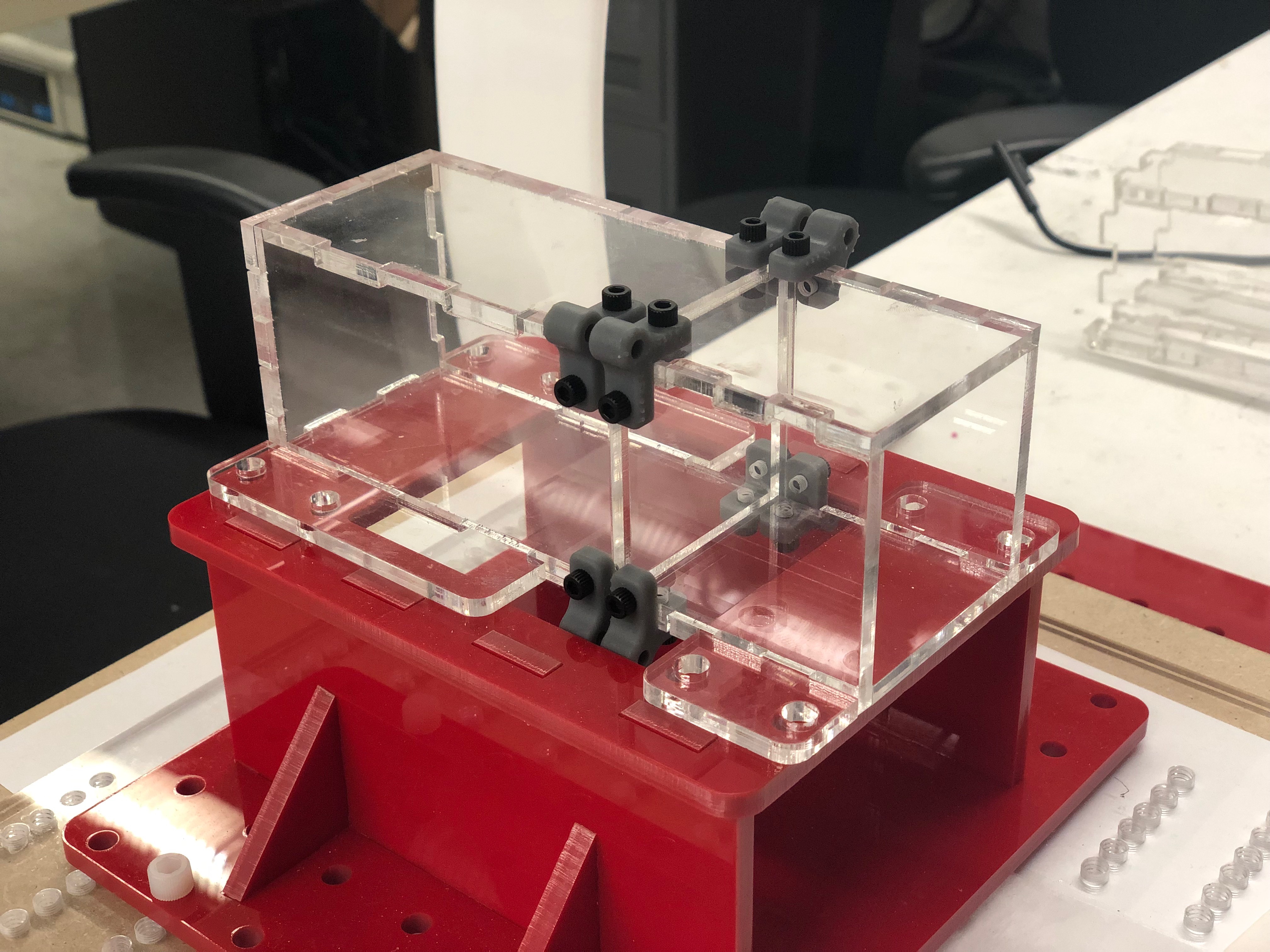
I also finished laser cutting and assembling the updated phantom boxes and their corner pieces. When we assembled the initial phantom boxes and clamped the membrane between the two boxes, we noticed that the corner pieces were pulled/angled toward each other and didn't look secure. We've updated the design so that each corner piece will have two extra screws through them for reinforcement.
July 17
This morning, a group of high school and undergrad students from the med school came to the lab for a tour, so I got to see some of the other things going on in the lab. I could also try out the needle system for myself (the one with force feedback) since the whole thing was set up, so that was pretty cool!
We also got the parts for the user side from the 3D printer, and those turned out well. I'll have to redesign and print the handle, since it's fairly heavy, and we don't want its weight to influence user performance. I've edited the CAD model already so that the center is hollowed out, so it will have the same shape but a lower density/weight.
I also started to assemble the follower side of the system, but then I noticed that the height of the acrylic plates varied, and the other parts depend on the height being a uniform 1/4" each, so not everything was fitting or lining up properly. Sam and I concluded that we'll have to redesign it with one plate and modified parts, and print and laser cut again.
July 16
CAD model of the user side
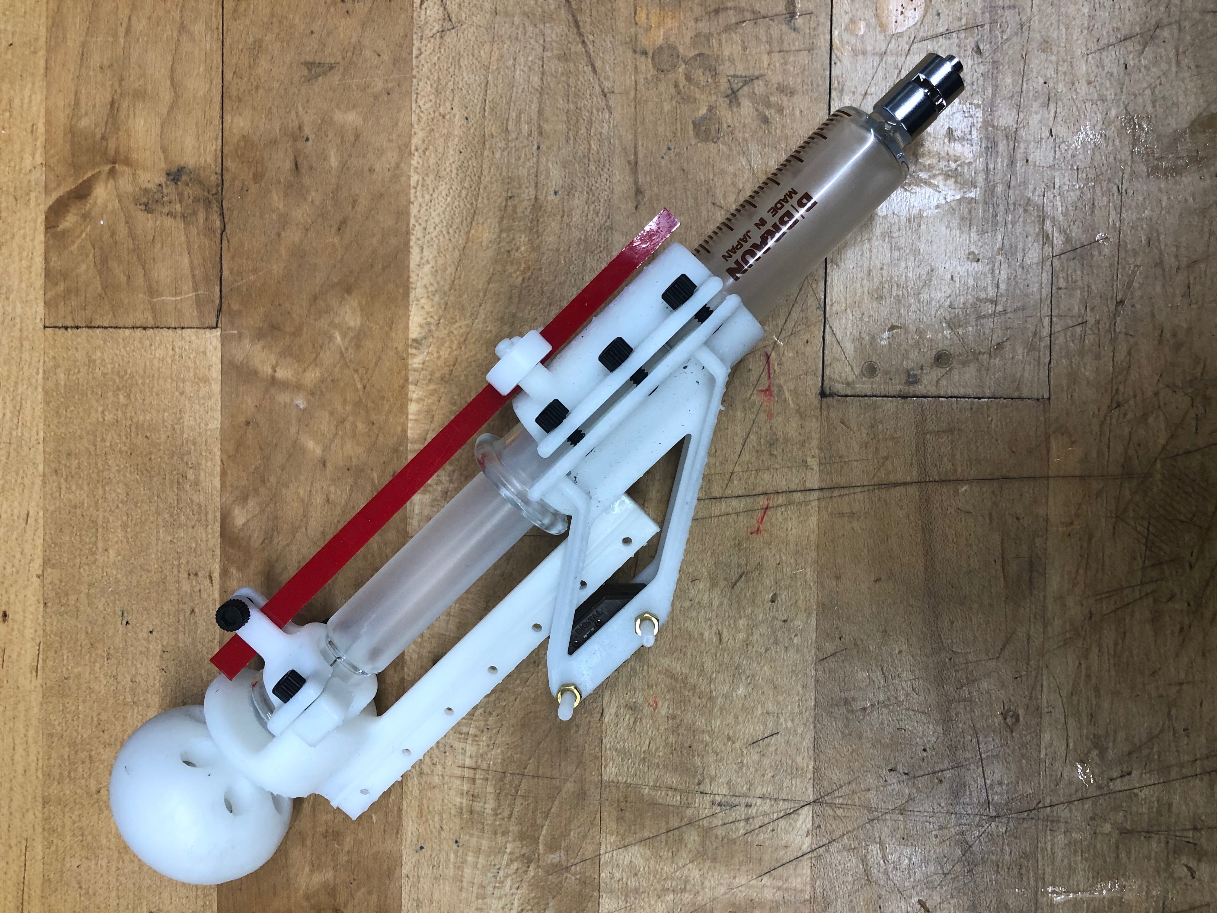
This morning, I finished the user side of the system. It's designed to be attached to the syringe by clamping the two green parts together around the cylinder, and the dark green part on the bottom holds the encoder. The blue parts attach to the end of the syringe, and the handle (light gray) is fastened to the light blue part. This way, the user moves the encoder strip through the encoder directly in a simplified system.
After I finished the CAD model, we 3D printed these parts, as well as some that needed editing. I then went to Room 36 to laser cut some acrylic for the follower side, another edited phantom box, and a couple edited urethane molds. Then I went back to the lab to tap the acrylic and start assembling the follower side.
July 15
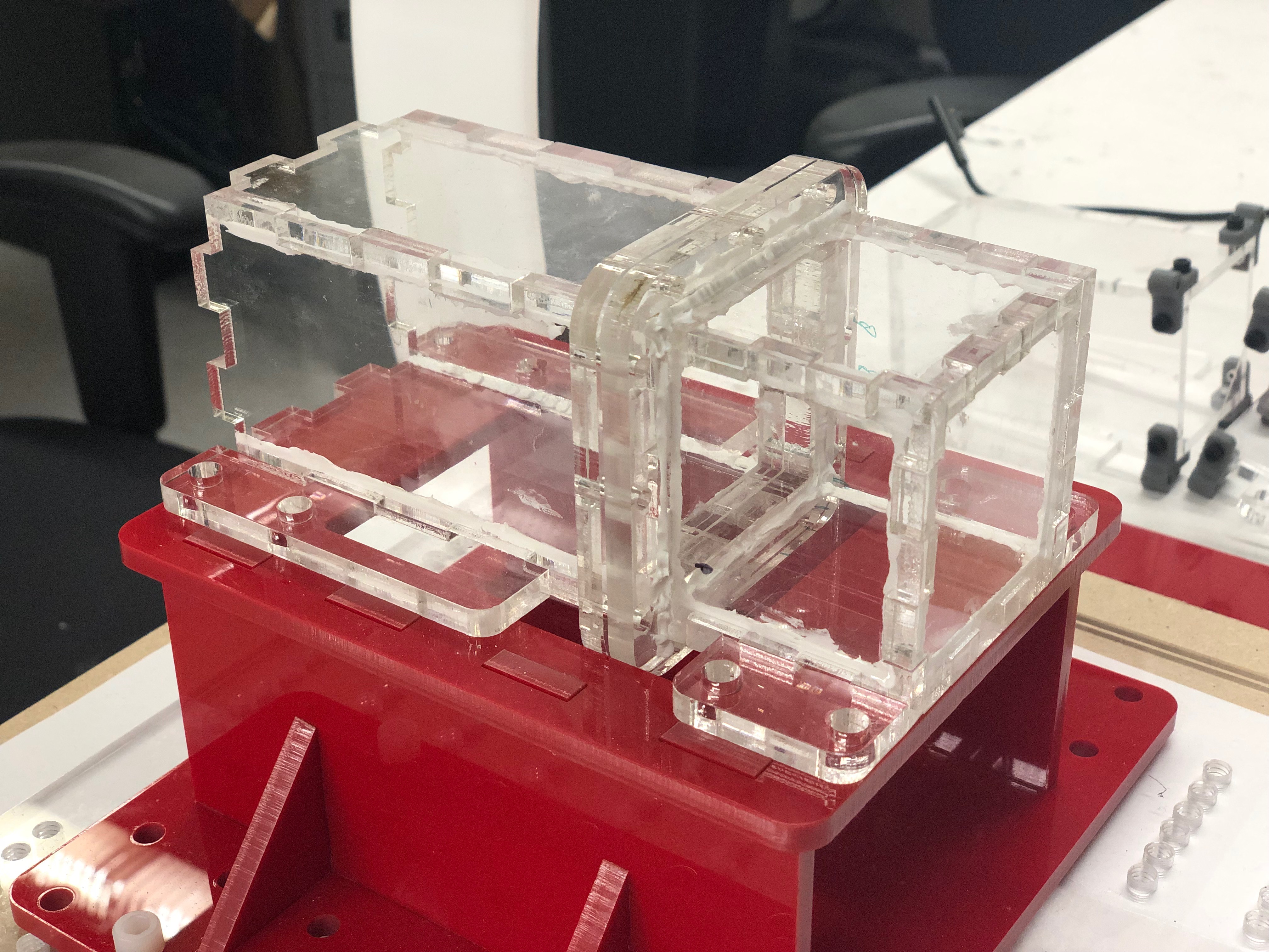
I spent most of today getting ready to assemble the follower side of the system by preparing the 3D printed parts and tapping the acrylic parts. Sam also showed me how to prepare the agar, as well as the process for molding the agar in the phantom box. Since the urethane membrane has to be in the middle of the agar, the molding process is a little more complicated than simply pouring the agar into a mold. We first have to pour the agar into the bottom half of the phantom box, then place the membrane on top of that, then place the top half of the phantom box on top of the membrane so that the membrane is sandwiched between the top and bottom boxes, then clamping the three pieces together. We designed the urethane membranes with small holes in them so that when pouring the agar into the top half of the phantom box, the agar can seep into the bottom box to fill in the gaps. This makes the phantom as uniform and homogeneous as possible.
For the rest of the day, I focused on CADing the user side of the system, with which I'm just about finished. I'm planning to 3D print and laser cut some final parts tomorrow, so the construction is close to being finished!
July 11
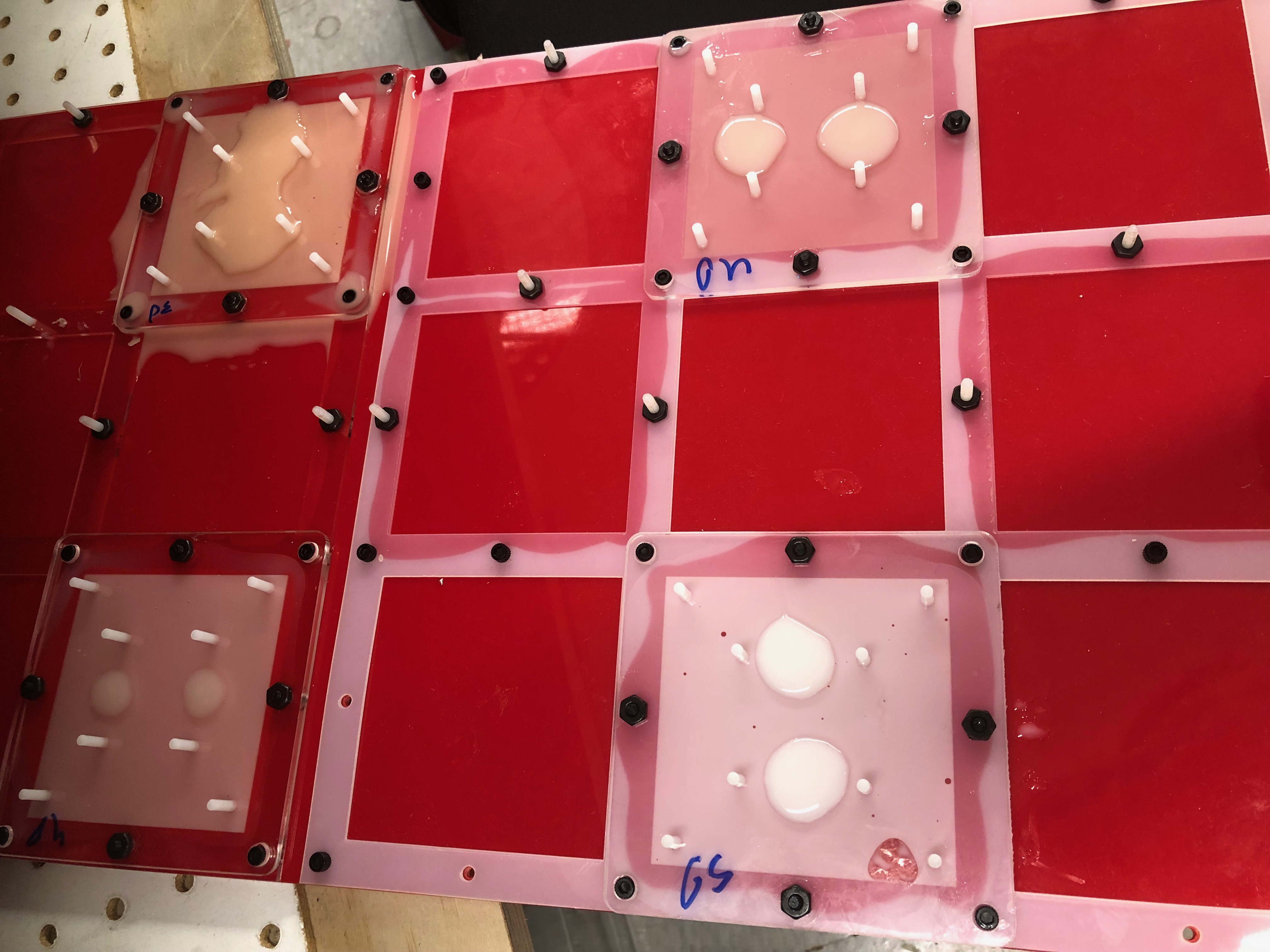
We checked out the molds this morning, and it seemed like we hadn't quite applied enough mold release - they took us some time for us to pull them out. There were also some bubbles that had made their way into the molds despite the degassing, so we'll try to avoid that for next time. However, the thicknesses and stiffnesses did seem to be appropriate. After we mold the agar (the material we'll use for the phantom), we'll be able to test the urethane membranes. Sam and I went to Room 36 today to laser cut and 3D print the parts for more phantom boxes so we can have those for testing the membranes.
Cured urethane molds for testing
I also had my first small group meeting with Mark and the "medical devices corner," which consists of just Ali, Ileana, Sam, and me. After the meeting, Sam and I showed Mark how we've improved the response of the follower side. Shortly after, Sam and I were trying out the transistors, and the motor stopped working completely. We were trying to debug it for quite a while, and it wouldn't even work with only the external power supply (minus the Arduino). After I went home for the day, Sam messaged me that he finally got it to work by setting the minimum rotational speed to 30 rpm by timing the rotations.
July 10
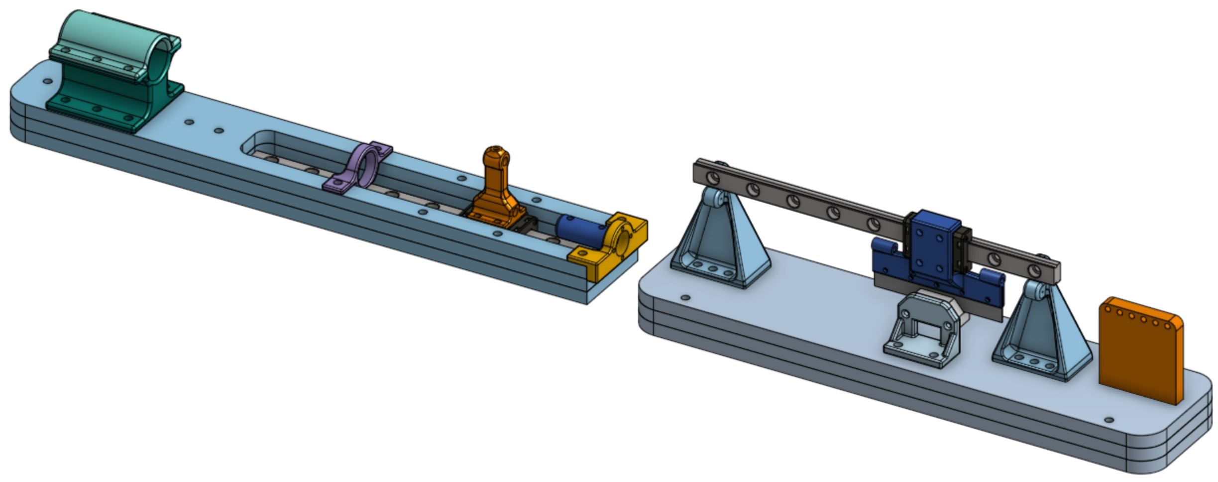
Today I finished up the follower end of the system, and then I got started on the user end of the system. The user's side will consist of a syringe that will mimic a needle used for surgical biopsies. The syringe will act as a piston to pump a viscous fluid, in our case oil, to another syringe such that they will have the same motion, but the second syringe won't actually be doing anything of use. This makes the user feel as though they are controlling the needle of the surgical robot, when in reality they won't be puncturing through a membrane. The follower end, however, will puncture through a membrane. The experiment is set up this way so that the user won't feel any force feedback on their end because they won't feel the needle puncturing through the membrane. The two ends, however, have the same motion, and the follower end just mimics the user end.
Final CAD model of the follower system
Urethane molds after casting
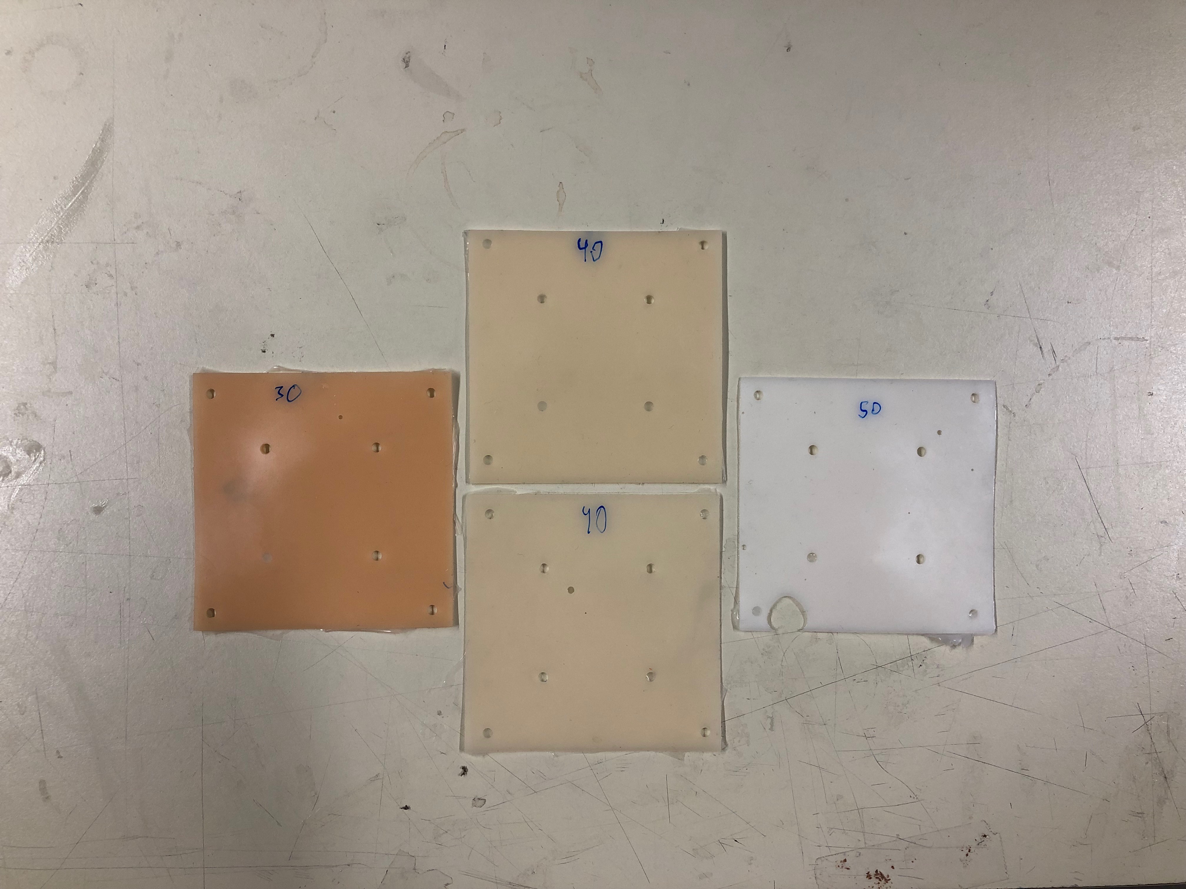
Sam also showed me how to cast the molds for the membranes. We're not sure exactly what the thickness and hardness of the membranes should be, so we cast a few different materials (VytaFlex 30, 40, and 50) of different thicknesses today, and we're hoping to test those out tomorrow.
July 8-9
For the past couple of days, I've mostly been CADing. I finished a draft of the follower end of the robot yesterday, which includes both the encoder system and the syringe/needle system. Sam looked it over and made some suggestions for improvement, and I'd been working on those for most of today. I only have a few quick edits to make, and then I should be done with the follower side. I've been learning a lot about CAD design through this project that I haven't really gotten the chance to learn before, like using Tap & Drill Charts for specific dimensions on screws and their respective tap sizes, and also thinking more critically about how a part I'm designing will behave under stress.
I've also been trying to understand transistors, and electronic parts in general, more for the sake of improving the electronics side of things. We think that by having a built-in on/off switch that can be controlled by the Arduino, the motor will have a quicker response to rapid changes in position. Currently, it seems like the Arduino has some sort of safety feature such that when there is too much current, it'll stop supplying current completely. We're hoping that by integrating a transistor into the circuit, we can have the current flow directly to the piezo motor from an external power supply, rather than from the Arduino, and the Arduino will just control the switch of the transistor. This will theoretically be our way around that safety feature. A lot of the electronics stuff, including transistors, are new to me, so I've been trying to understand the current circuit more. I'm definitely learning a lot!
July 5
I spent my morning CADing some more, and finished most of the encoder side. Then Sam and I spent the rest of the day trying to debug the entire needle system. All of the DACs have come in, and we've tried out one so far. However, the issue with the needle system doesn't seem to be entirely due to the DAC. The motor runs properly with pure logic, but once we try to control the needle with the encoder on the user end, the motor doesn't respond to rapid changes in position. We figured out a quick fix to sort of cheat the electronics, and also played with the gains of the position control and derivative control, which all helped improve performance so that the needle end moves (roughly) the same as the user end. We're hoping to get more insight as to why the system is still not responding to quick changes soon, but for now we have a quick fix.
July 3
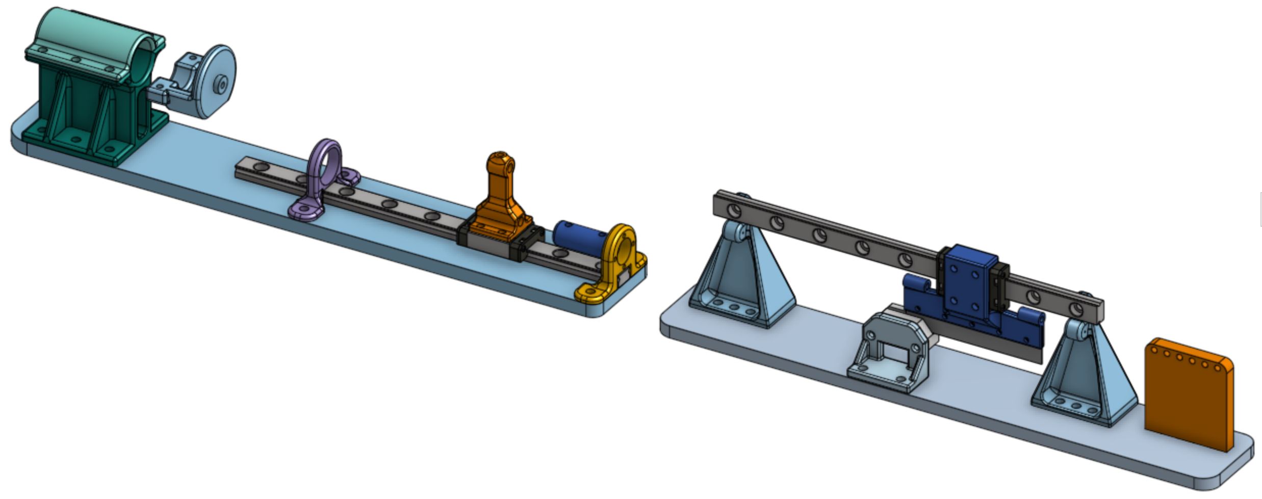
Today, I spent the entire day CADing again, and I finished half of the system, which pulls the syringe. The picture below shows the previous system I'm improving upon. Note that the part that moves the syringe, which is connected to both the screw and the universal joints (black), slides between two small plates, but has no definitive track, which causes it to wobble and jerk when moving.
CAD model (left) and assembled design (right) of the syringe system
New design of the syringe system
On the right is the design I just finished CADing today. Rather than having two plates act as tracks, I incorporated a linear rail with a carriage, pictured in gray, to guide the syringe. This will hopefully allow smoother motion of both the 3D printed part and the pump of the syringe.
I also started on the other half of the system, which includes the encoder, which basically tells the needle how much to move. I'll be finishing that on Friday, then I'll hopefully have time to go to Room 36 to laser cut and print the CAD model. Two of the DACs also came in today, and the third should come in on Friday, so Sam and I want to test those out on Friday as well.
July 2
I pretty much spent the entire day CADing today. Since I'm trying to improve on the system that Sam has already designed, I'm incorporating some new parts and need to redesign almost all of the custom parts he's made. It's taking me a while, but I got a fair amount of work done today, and I'll hopefully have the design finished by tomorrow so I can 3D print and laser cut on Friday.
July 1
I came to lab a little later this morning, as I will on most Mondays, after GRE Prep and a diversity workshop through the SURF program. Despite a late start, I still had a pretty productive day!
Previous design of the phantom box
Current design of the phantom box
I went to Room 36 to pick up the 3D-printed parts, then came back to the lab to let them cure in the UV oven. Then I could finally finish the phantom box, and I think it turned out pretty well! I've included some pictures of the previous design and the current design for reference. The previous design doesn't provide clear visibility of the needle as it passes through the membrane, which would be between the two plates at the end of each box. This is because the laser cutter doesn't quite provide a smooth cut. The current design, however, eliminates the need for the two plates, allowing for greater, clearer visibility. We still have to seal the corners of the box with silicon to prevent the gelatin (for the phantom) from seeping through the cracks when molding, but other than that, the phantom box is done!
Sam and I also ordered a few different digital-to-analog converters (DAC) today. One problem with the current system is that the piezoelectric (piezo) motor, which is used to move the needle forward and backward, either stops working or doesn't move quick enough when we try to move it at faster speeds. Sam and I believe that the current microcontroller we're using, which has two built-in DACs, is not converting the digital signals properly, which affects the ability of the motor driver to change the speed of the piezo motor. So we want to try some different external DACs with greater voltage ranges, and hopefully this will fix the problem. Sam took me through the whole ordering-parts process, and at least some of the chips should arrive by Wednesday.
June 28
I attended my first lab meeting today and got to know some of the other undergrads in the lab during the lab cleanup. Simone and I cleaned up and organized the soldering station for most of the day. Then Sam and I went to Room 36 for some more 3D printing and laser cutting. The laser-cut parts came out great, and we'll pick up the 3D printed parts on Monday. Then the phantom block should be finished!
June 27
We went to Room 36 today for some 3D printing and laser cutting for the phantom block, but only got to the 3D printing, so we'll laser cut tomorrow as long as we have time outside of the lab meeting and cleanup. Then we can (hopefully) finish assembling the phantom block. Sam also showed/explained the robotics system to me in more detail, and we identified things that need improvement so that I can take over the project in a few days.
June 26
Today, I got a better idea of what my project for the summer will be after Sam showed me what he's done so far. The goal of the project is to design an MR-compatible device to assist with needle procedures by providing both visual feedback and force feedback to the user. I'm helping with the control of the experiment, which will consist of visual feedback only. Most of the system is already built, but I will be helping to improve it. One of our first priorities is designing a phantom box such that a picture can be taken from the outside of the box that will clearly show the position of the needle with respect to the membrane.
So today we went to the Room 36 in the PRL to do some laser cutting for a new phantom box. However, the first cut didn't go as planned, and so we had to print a second time. After going back to the lab, we realized that the current design would result in a distorted image of the needle, so we did some more brainstorming and came up with a new solution. I started CADing this new design in OnShape until I had to leave for a SURF workshop, but we should be able to go back to Room 36 tomorrow for laser cutting and 3D printing!
June 24-25
My first couple days in the lab were fun and quite productive already! Sam has been helping me get acquainted with the lab and its projects. I'll be working on the project involving medical robotics designed to assist with needle procedures (more details to come).
During my first two days, I received training for the Product Realization Lab (PRL) as well as Magnetic Resonance (MR) Safety Training at the Lucas Center for Imaging. These will allow me to 3D print, laser cut, etc. in the PRL, and also conduct experiments using MRIs in the Lucas Center. I also helped Sam with some CAD work on OnShape, a cloud-based CAD program that's new to me, which we'll use as a mold and holder for the phantom used in experiments.