-- MattEstrada - 21 Jun 2011
Summer Research
June 20
- Introduction to the lab took all day. Listened to a lot of people talk about their research, all of which seemed pretty cool.
- Introduction to my past projects:
- Learned to fabricate gecko adhesive (Directional Polymeric Stalks variety) using a mold Sangbae had brought over with him
- Worked on process of fabricating a composite leg (foam core with 2mm plastic shell). Learned more about casting materials and creating toolpaths/running the CNC mill.
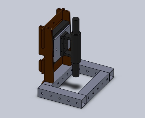
- Designed and built a test gantry to simulate running for a single leg. More practical building/ordering from Mc Master/designing for minimal assembly.
- Vague goals for this summer
- Learn tons of useful skills for robotics
- Come out with some solid progress in at least one project that helps out the lab
- Get a tan after spending the past 3 years in New England
- Thoughts on cool projects I'd like to work on
- Gecko Adhesive seems super relevant to my past experience and a good way to dive into something quick.
- I think it would be cool to pick up something in addition so that I can have a distraction from banging my head against the desk when gecko adhesives aren't coming out right
- It would be useful to build my background in practical electronics, an area which I am inexperienced in
- Mechanical design and building is always a fun job
June 21
- Noe gave me the details on the state of the indenting process
- Useful to think of adhesion in a 2D state-space (Normal Pressure vs. Shear Pressure). Failure points at different configurations encircle an area of safe operation for adhesion.
- Process of indenting is done on the mill. The z-axis is zeroed by shining a light behind the stock and the tool is lowered until it blocks out all the light. The mill advances at an angle matching the razor to indent into the wax.
- The Levil mill cannot make things flat enough for our purposes. It has a >10 micron error over the workspace. The HAAS will hopefully be better.
- Used Image Pro Plus on the microscope to measure stalk height, interior angle, and backing thickness
- A discrepancy showed up between the stalk characteristics aimed for and what was actually measured. The stalks indented at 30 deg and 40 deg were both ~20 microns shorter than desired. The ridges also had a larger interior angle of 30 degrees rather than 20 degrees.
- Went with Eric to the machine shop while he measured some tool dimensions and tested commands. Maybe he will let me touch the mill by the end of the summer.
- Barrett gave a tutorial on how to use the Adept robotic arm and sent some tutorials.
June 22
- Signed up for a Mendeley account. Still a little unsure how to use it, but I'll ask around.
- Sat with Eric in the PRL while he did more prep on the HAAS, but I did some lit review and picking his brain about indenting this time.
- Played with the Adept arm, but only turned it on an controlled it manually.
- Read some of the manual on files and directories. It's a little unintuitive but doesn't seem too hard. Next on my list is to write a program.
- Spoke to Barrett about the desired key task for the Adept.
- Open loop control, seems like I just have to move the hand forward and rotate, unless I misunderstood.
- Doesn't seem to be much compliance in the system (Rigid robot arm/metal hand/rigid key/rigid lock), so if I'm off by a little bit, it's probably going to fail. Hopefully the key would just slip out of the hand instead of breaking something.
- Need to hack together a mount for the lock (and also buy the lock)
- Not sure how hard it is going to be to align the center of the key will the axis of rotation on the robot arm
- Noe went over how to use the inking platforms. The home-made micro-controller was cool. I took notes on the somewhat cryptic display, which only has a few, basic functions so it's not that bad.
- Still need to mount the camera at the correct height for the inking process.
- Need to figure out how we are going to mount the wafer to the underside of the glass in the new inking platform.
- Noe took Thea and I over to the LFL to show us the casting process, quartz wafers, microtome mount (but not version 2.0), and wax block. I think I've seen all the tools and materials used in the process now other than the Matlab script/Gcode toolpaths.
- I'm excited to get started indenting and inking, but I expect the pain to set in shortly thereafter. Blood, sweat and tears usually go into making things that are super tiny.
- Read some articles on adhesion, but still have more to go.
- "Microindenting for the Manufacture of directional dry adhesive" (2011)
- Paper submitted by the lab in May (?). Helped me understand the process a little more.
- "Surface energy and the contact of elastic solids" (1971)
- Pretty theoretical & mathy. Talked about surface forces and energies. I didn't understand most of it too well so I may go back and read it again if I think it will help understand adhesion.
- "Thin-film peeling: the elastic term" (1975)
- Short & concise theory on peeling
- "Microindenting for the Manufacture of directional dry adhesive" (2011)
June 23
- Lab Retreat
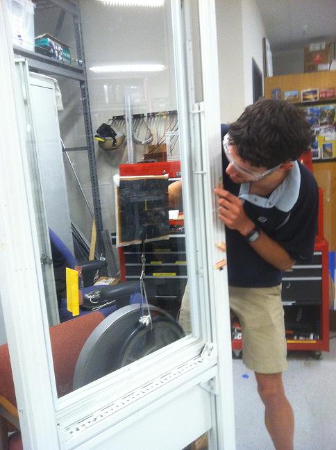
- 'First goal for this summer is getting somebody to climb a glass wall !!'
- Mark mentioned creating a wall with slots for pegs to practice two-point climbing. It would also probably be helpful to rig up a belay system and do some research on rock climbing, but I'm not sure when I'll find time for that.
- Would also like to pick up some mechatronics skills
- Personal goal: Make friends.
- 'First goal for this summer is getting somebody to climb a glass wall !!'
June 24
- Read some more papers
- "Effects of contact shape on the scaling of biological attachments" (2005)
- "Adhesion and friction in gecko toe attachment and detachment" (2006)
- "A microfabricated wedge-shaped adhesive array displaying gecko-like dynamic adhesion, directionality and long lifetime" (2009)
- Adhesion meeting
- Notes to self- software for creating toolpaths is on John's computer & on the laptop
- Make sure not to go past the machine's workspace, which is about 2" from the edge of the mounting block
- The directions for measuring tool dimensions is not correct on the twiki
- BDML Meeting - brainstormed ideas for perching then crawling around on the side of a wall
- Regrouped with adhesion team and discussed immediate plans for improving inking process
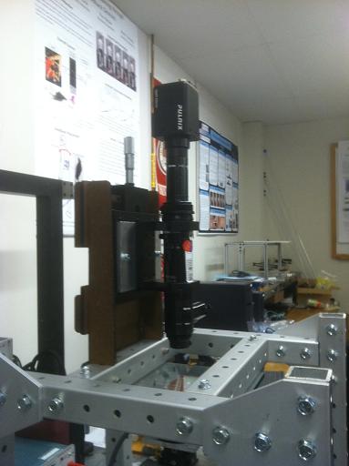
- Going to try to mount the camera for a birds-eye view of the inking process due to spatial constraints on the rig
- It would be ideal to do inking solely on pressure-guided feedback in the future
- Bringing in a heat lamp to speed up curing process. Heat the sample to 75-95 C and it should take ~30 min, which beats 36 hr.
- Going to try to mount the camera for a birds-eye view of the inking process due to spatial constraints on the rig
- Homework: design & build a mount to hold the camera
- Mount is going to be made out of masonite and cut out on the lasercutter. An adapter between the vertical slide and camera also needs to made out of aluminum. I'll ask someone to come with me to fabricate these on Monday to make sure I don't blow anything up the first time I use the particular machines we have here.
- Quick research on peg boards- used to build upper body strength for wrestlers, and potentially to practice climbing with gecko adhesion?
- Demonstrative video - http://www.youtube.com/watch?v=p1NwRfWeHIY
- Models that would probably be useful to us range from $185-$350 on this website. Each is 6' tall... not sure if they come with pegs
- Super basic instructions on how to make a climbing peg board
- http://www.ehow.com/how_6780712_make-climbing-peg-board.html
- Usually made out of 2" thick hardwood finished with 3 coats of clear varnish (optional). Perhaps two parallel 2x4's would do the trick? It would be cheaper.
June 27
- Spent the morning with Elliot in the LFL as he walked me through the specifics of the laser cutter. We did some quick math to compensate for the laser width and the pieces that fit together came out to a nice press fit.
- Went to the Thermo Sciences building with Noe as he walked me through the specifics of their Bridgeport mill to make an adapter to attach the camera's base to the one axis slide.
- Walked over to the Physics shop and Noe showed me how to buy bolts and other supplies.
June 28
- Bolted the camera to the three axis-slide
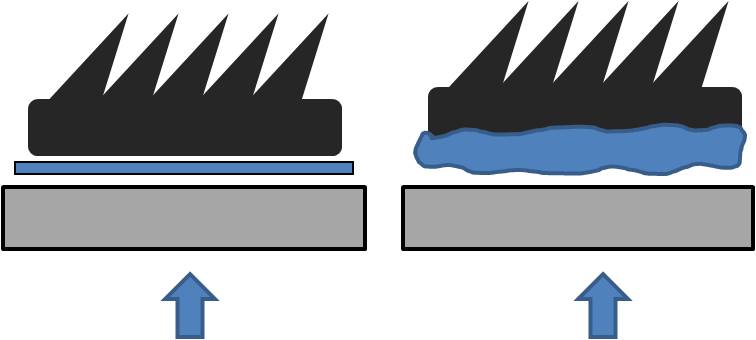
- Practiced inking a piece of indented adhesive with Noe using the top-down view only. There was difficulty interpreting which bands of light and dark areas represented the tips or bases of the stalks, but we reached a consensus. We loaded the patch of adhesive using the same pressure reading as a post-treated sample had recorded before.
- A heat lamp was used to accelerate the curing process. The target temperature was 80 C. Recommended curing conditions are listed below. Originally we mounted the lamp too far and it reached a steady state temperature of 50 C, then I moved it closer and the temperature rose to 100 C and caused a crack in the tempered glass to propagate. Fortunately we have extra, and the sample did cure.
- 30 min at 70C
- 11 min at 100 C
- 7 min at 150 C
- Upon inspection under the microscope there seemed to be uneven inking. Some patches were matted over, which others appears to have no post-treatment. We thought this was probably due to the sample being uneven.
June 29
- Change of plan for inking on the new rig: we probably need the side view in order to successfully post-treat samples. I Designed another camera mount to be able to fit the camera in the three-axis rig to do this. This took up the majority of the day since it was a little challenging to make everything fit spatially. The majority of the setup has to be lowered so the center of the camera lens can fit in the same plan as the sample.
June 30
- Built the mount and did most of the alterations to the rig. I had to iterate the design once more to fix some more sptaial problems I hadn't realized would come into play. Luckily this stuff is just made out of masonite.
July 1
- Camera is mounted on the side of the rig!
- Another attempt at post-treatment causes us to realize some more shortcomings in this setup. We need a smaller piece of glass to get the sample in focus.
July 5
- Went with Eric to the PRL to indent the new piece of wax.
- Fixed the glass to allow for the camera's plane of focus to reach the sample
- Cleaned wafers, but the rest of Sylgard was used to cast the newly indented wax so I couldn't try post-treating samples.
- Later found out we have more Sylgard in the cabinet
July 6
- Tried out using various methods to self-align the sample and the wafer during post-treatment. A piece of foam, double sided tape creeped too much over time. A rigid, universal joint, with light foam around the edges to hold the sample somewhat horizontal seemed the work the best.
- Compared top and side views of loaded ridges at varying forces. Care was taken to make sure we were looking at the same ridges.
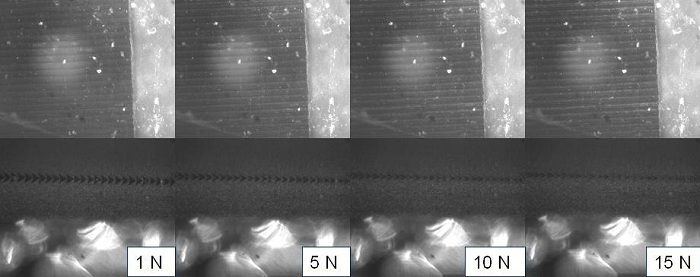
- Post treated a sample using the camera at a side view and the universal joint.
- Loaded it to a pressure of 6N
- Maybe I will speed up the curing process by heating it tomorrow
July 7
- Successfully heat treated the sampled pressed yesterday.
- Analyzed the sample under the microscope. The sample seemed to be pressed at one end more than the other. There were also some spots that were clearly mashed.
- The universal joint seemed to be misaligned with the center of the sample on one axis. This probably caused some problems.

- There seemed to be almost no drop in load from the force sensor when the sample was backed away.
- This could be due to creep in the joint I made, or from expansion of the materials while I heated it up to cure? I let the setup cool for maybe 10 or 15 min before I backed it off.
- Read some indentation theory
- Met Aaron Parness, I recognized him from the episode of "Prototype This!" where they attempted to climb a wall with gecko adhesive.
July 8
- Arduino tutorial in the morning. Got a quick intro but still have to make a paper bot.
- Weekly dhesion meeting with the team
- Cutting ridges into separate sections may be useful. We would do this after the ridges are molded, although I'm not sure whether we would want to do it before or after inking (probably before).
- Valuable lesson from Alexis: get to the MERL bbq's early every Friday to be first in line
- BDML weekly meeting. Talked about the new wiki home page and learned about the exhaustive fab that Berrett has been doing for the robot hand.
- Paul walked me through indenting on the Levil in the afternoon and I took tons of notes. Some things I can play may be using the carbide blade with a smaller interior angle to pack more ridges into a tighter space. Eric had mentioned indenting into a soft metal, but I don't know how far off that is. It would be nice to have a somewhat permanent mold so I think that may be something we want to explore.
July 11
- Post-treated a larger sample from the HAAS
- A big patch clumped in the middle, which could have been due to the point contact with the universal joint supporting the glass slide.
- Curing the sample under heat appeared to cause thermal expansion in the rig (ie in the 1" block of aluminum directly under it). This presumably caused the sample to compress, as indicated by the mashed patch in the middle and the rising force output from the sensor.
- Further investigated the possibility of thermal expansion. Shining the heat lamp on the force sensor alone did not cause a large enough variation and a back-of-the-envelope calculation for the aluminum expansion under these conditions comes out to the right order of magnitude. This is probably what is happening.
- Solution I'll make the backing to the universal joint more rigid by using metal to ensure there is no flexing. I'll also stay attentive to the force readout and adjust the position to keep a somewhat constant spacing while it heats up.
- Looked more into indenting with the thinner carbide blade and collected the pieces for the mount. I should be able to indent on the Levil within a couple days.
July 12
- Went to the PRL with Eric to clean the shell mill and do more indenting experiments. We may want to order some new carbide inserts for the tool in order to get a smoother, flatter finish on the wax
- Ran some tests indenting with the thinner carbide blade on the Levil. I tried a couple indenting angles and spacings, although only over a small range. This wasn't an exhaustive test; I just wanted to practice indenting with the blade and run into the initial errors I'll make inevitably make with the process. I cast the silicone as well, so hopefully I can demold tomorrow.
July 13
- Post-treated a salvaged piece from discarded HAAS indentations. The back had to be separated from the glass slide it was laid against since it cured onto it after being relocated? The uneven edge seemed to affect the quality of post-treatment
- Cut up the indented sample I poured yesterday, results to come
July 14
- Results from the carbide tool, only one of my samples yielded interesting results. This was with the carbide blade indenting at a center line of 57 degrees at depth of ~130 microns, spaced 50 microns apart.
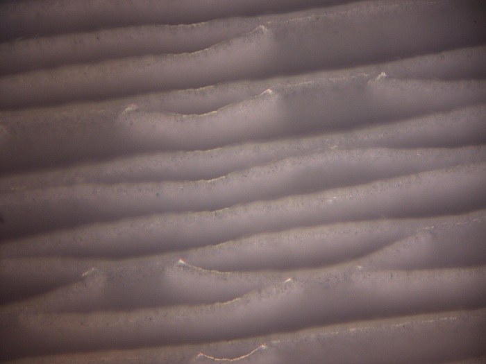
Clumping is apparent from the top
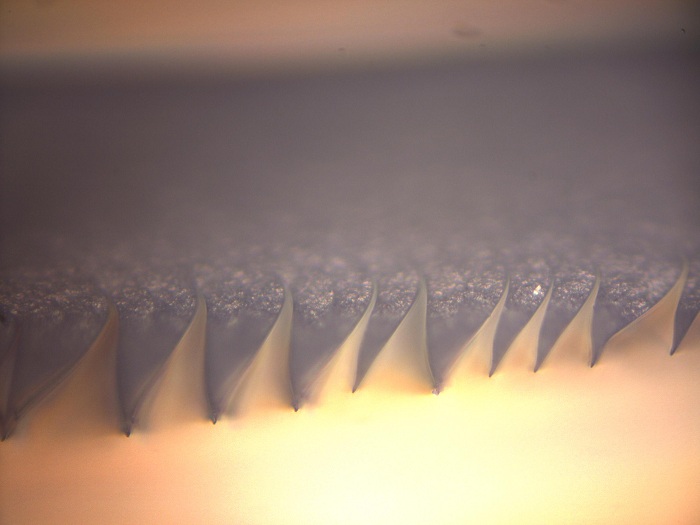
Clearly showing stalks clumping together in profile
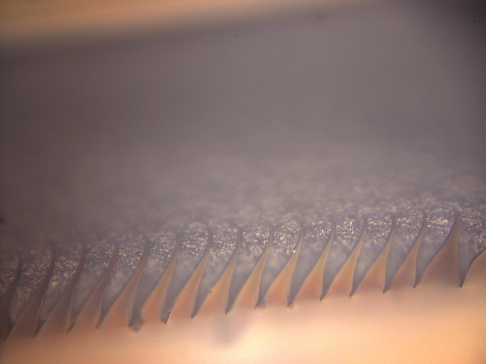
Better results from the same cross section
- Post-treated another indented adhesive
- Adjusted the position of the rig to maintain a constant force on the sample as I heat-cured it
- Less matting this time around since I tried to cure at a lower pressure on the ridges
- Better results--the 1.5"x1.5" sample held 15lbs up to 25 degrees and then 20lbs up to ~12 degrees, which is a better pull-off angle than anything recorded with E18 according to Elliot
July 15
- BDML meeting + Adhesion meeting + MERL BBQ
- Machined simple delrin molds and poured wax cylinders to be used for finding wax material parameters to model indenting.
- Ran the numbers with Elliot and the pull-off force for climbing with this adhesive is about 25lbs for his climbing paddle, which is probably too much. This was calculated by scaling up the post-treated sample I gave him yesterday. We should either use less adhesive or perhaps have the stalks less angled.
July 18
- Spent the day indenting at different angles on the Levil, there appeared to be mixed results from what I could tell from the wax so I may have to do it again. Lesson learned: indenting at three different angles is almost three times as much work. I'll demold and investigate tomorrow.
July 19
- Inspected samples that were indented yesterday, the results were disappointing. There are serious problems with close-up. I also didn't align the blade very well in subsequent tests--probably haven't mastered the art of it. I should snowplough the wax with the razor blade all the time, I had skipped this step on some of the different angles. This produced inconsistent results through the length of the blade.
- Indented again, the wax looked better this time. I did three batches
- 20 deg from vertical spaced 50 microns apart
- 20 deg from vertical spaced 60 microns apart
- 30 deg from vertical spaced 60 microns apart
July 20
- Talked to Noe and Eric about the problems I've been seeing with my indentations. There is probably slop in how the blade is being held. I took some extra precautions when I indented again.
- Sanded down the interface that holds the blade in order to remove gunk from the mount
- Made sure to tighten down all the bolts extra tight in the machine
- Made measurements on most of my previous indentations They are either too fat and too short, or they are suffering from close-up. Both do, indeed, point to rigidity being our problem.
July 21
- Met with Draper labs to show them our progress on indenting
- Looked at final row of the indentations I had made, which was particularly telling. The last row is taller and fatter. This points to close-up.
- The interior angle of the indentation was much more than the blade's interior angle, so much so that it made me double check the Gcode, however, this is correct.
July 22
- Indenting meeting
- We probably have strain softening in our wax, according to Paul's experiments
- Maybe FEM isn't the way to go go to computationally model indenting
- Try clamping something we know is rigid and inspect the indented trajectory on the Levil
- Did another set of indentations. I did a set varying spacings to see if I can back off enough to diminish the effect of close-up and doing a pattern of a single, double, then triple set of indentations to see what is happening from row-to-row.
July 23
- Single indentation looks super straight, others not so much. Clearly the way the blade is loaded changes from the initial to subsequent indentations and this affects the shape that we carve out.
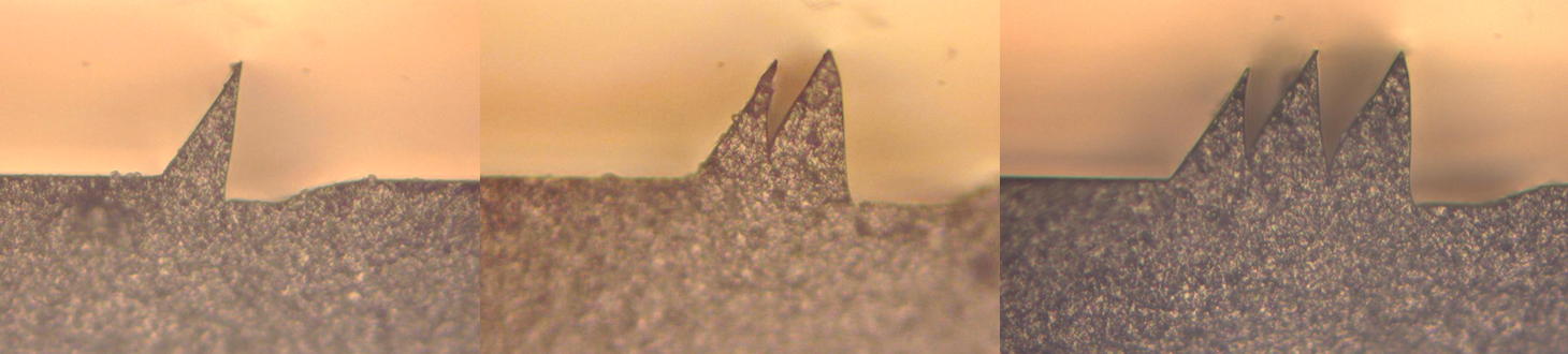
Single, double, and triple indentations show different shapes
July 25
- Talked to Elliot and others, at this point we might even want to consider setting up the camera next to the Levil and seeing if we can get a live picture of indenting. Paul and Noe wanted to avoid it, but we're pretty confused on what's going on right now.
- Spent the majority of the day in the PRL with Eric as he ran some indentation experiments that are trying to hone in on our problem. He walked me through running the machine.
July 26
- My day was eaten up my preparing for the lab tour Violeta and I were giving other students in our summer program, then tracking down the receipt in order to get the food purchase approved. I didn't get much done :(
- Spoke to John about our process right now and he gave some really good advice
- The goal right now is to eliminate variables in the system. I don't completely understand what is going on, so I need to take measurements, do experiments, and do some calculations to start crossing off possible culprits. I suppose this is common sense but it helped to hear someone say it.
- Stiffness of the Levil, stiffness of different points of the fixture, a rough idea of the flatness of our blade, etc, are all good things to have an order-of-magnitude approximation of.
July 27
- Eric thinks that our problem is the way we are clamping the blade in our fixture, his experiment showed a pretty clear correlation between the length that the blade was sticking out from the clamp and a loss of fidelity in our features. As a result we spent a large part of the day brainstorming a new design for the clamp that fixes two problems.
- The 2mm of tapered razor blade sticking out of the clamp is deflecting (it is a cantilever beam, after all). The goal here is to brace the beam as close to the tip as possible. We hope to do this by sticking the blade recessed farther into the clamp and filling the gap between the clamp wall an tapered blade edge with a malleable metal.
- The clamping force for the larger blade is not sufficient. We are adding more bolts to the new fixture design.
- Looked at the problem of a tapered beam bending--which is not as trivial as I had originally thought.
July 28
- After deriving the PDE for tapered beam deflection and looking through a couple textbooks, it became apparent this is just best done computationally. Noe already has the code for it, but I think it'd be a nice exercise to do in Matlab.
- Scuola Superiore Sant'Anna has a solid bio-robotics program according to Mark, remember this!
- Went to Costco with Morgan and Michela and bought everything for the MERL bbq (150 hamburgers and 50 hotdogs later).
July 29
- Adhesion meeting
- New task: get a picture of the indented wax. Mold a block of wax, cleave it in half then put it back together, indent along this center-line, take apart and inspect the profile of the indentation that we have gotten from the wax.
- This isn't very important to us so much as it is useful to the readers of the paper.
- It would be better if we could scribe lines on this wax, but it would be hard to get it at the resolution we need. Also, what type of ink works well on wax? Further investigation is needed.
- New task: get a picture of the indented wax. Mold a block of wax, cleave it in half then put it back together, indent along this center-line, take apart and inspect the profile of the indentation that we have gotten from the wax.
- MERL BBQ was successful. We were able to feed everyone and in a timely manner.
- BDML Meeting
- Kim and Violeta presented their work on Wet Adhesion
- Patio-behind-the-lab cleanup day, threw a bunch of stuff out
- Tried to help Violeta with drilling a bunch of tiny holes in a piece of shim stock for her device, but I got stuck on how to take the tool collet out. We'll pick this up on Monday so I don't risk damaging the Levil.
August 1
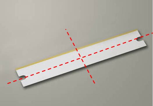
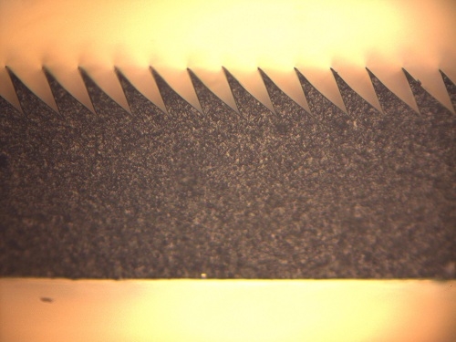
- Gauge block came in from McMaster, which is guaranteed flat to within less than half a micron. I laid the blade flat across it along each axis. These microtome blades are bowed to a maximum deflection of 40-50 microns away from being completely flat along two axes (shown in the picture below, the one I tested happened to be shaped like a saddle). The height of the blade (measured tip to back edge) was very consistent.
- Indented again, I had previously sanded the clamping fixture for the blade to a concave surface since I didn't use a flat backing while sanding. This was fixed--hopefully the indentations will improve.
August 2
- Mark suggested that once we have the experimental rig set up, we can vary cutting velocity to see how well our situation aligns with the Merchant model.
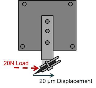
- Took a spring and loaded the fixture to 20N while measuring the deflection of the system at the tip of the blade. Under the loads we are seeing, we should only be getting about 2 microns of deflection seeing as we only see about 2N of horizontal load while indenting.
- Indentations show no sign of close-up but the stalks are still shorter and fatter than what Eric has been able to produce. Stiffness of the Levil doesn't seem to be a problem. The discrepancy between the first indentation and subsequent indentations seems to point towards the way that the blade--or possibly the wax--is being loaded? Frustrating.
August 5
- Adhesion meeting
- Fundamentals of Modern Manufacturing Ch 21 - well suited for senior/first year masters level explanation of Merchant Model.
- Rowe & Spick is a paper that we probably want to check out
- Suggestions for applying a grid pattern onto the profile of our wax are 1) Laser Printer 2) Imprint fine indentations then smear carbon over it
- Abridge outline of paths I can take
- Investigate easier way to post-treat
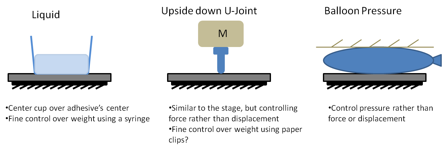
- Weigh down patches to post-treat instead of using the stage. It would help if I could have a more consistent patch size and stalk geometry in order to find the correct force that I need to apply to the patch.
- Look at different angles for the center-line of stalks to lie at
- This idea stemmed from the difficulty to detach a post-treated patch. Perhaps we would want to get the wedges to lie at a shallower angle (with respect to vertical) in order to trade off maximum adhesion for ease of removal.
- Further Thoughts to Indenting
- Can we compensate for our blade deflection/fixture compliance with a different trajectory? On second thought, we definitely need to understand what is happening with these simple trajectories before moving to more complicated ones.
- More Experiments on the 3-Axis Rig
- More zoom for a better view?
- Figure out how to get video capture on the color, higher resolution camera attached to the microscope. Will the Qcapture program do this for me?
- Etch lines on the wax!
- Investigate easier way to post-treat
- Noe helped me calculate the deflection of the tip of the blade. It turns out he had a script to do this for a tapered beam. If this numerical calculation is correct, the blade deflection probably isn't solely our problem (maybe it is if it's coupled with other compliances). Click on the link for a pdf image.
August 6
- Took video of indenting
- Flawed, I didn't realize that the script I was given both approached and retracted at the same angle. I will have to do this again.
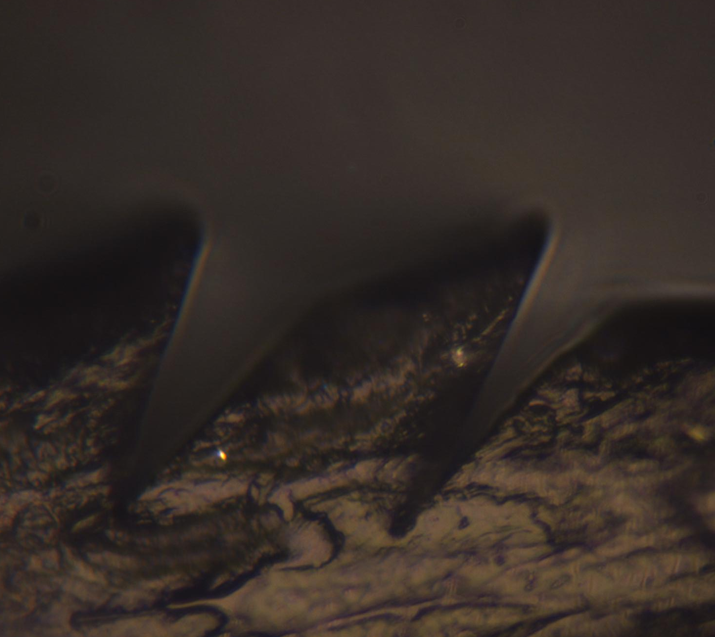
Current thoughts on Indenting : I am still getting stubby results! After looking at the video that I took, Elliot and I realized that the blade may be deflecting forward for the initial indentation, then backwards for the subsequent indentations. The video didn't yield many clues as to what was actually deflecting. It did provide some intuitive scale as to what was happening though. It is hard to believe that the blade is deflecting in the wax. Perhaps I still just can't see it? The problem is that I can't tell if it's the wax moving or the blade moving from the video that I have. The wax is only supported by double-sided tape, which makes me apprehensive. I also only see the tip of the blade, so I can only see the local deformation.
- Indented again at 30 and 20 degrees from horizontal. If my indentations are less-than-optimal but consistent, perhaps I can still compare the effect that varying the angle has on post-treated adhesion.
August 7
- Played with a couple of tweaks to the video capture setup
- Tried to install Q-Capture software to film on the higher resolution camera, but it looks like this is only designed to capture images. No luck.
- Adding a 20x zoom lens in addition to the magnification that I had before, but this proved much more difficult to focus. I may have to get Noe to help.
- Fixed approach/retract trajectory and captured better video
- Indentations yesterday still turned out poorly. The interior angles of each did not match up, so they are not two samples that would be good to compare.
August 8
- Status of Video : It appears that the wax is moving when I attempt to indent. I could tape down a larger patch so I can get more tape underneath it. It definitely appears that the whole block is moving rather than the blade.
- Status of Wedges : These wedges are still unsatisfactory. Not because of close-up any more, they are just fatter than what I should be seeing. I suppose this could be due to deflection of the blade still? It must be some compliance, we've already checked the trajectory. Maybe the close-up and fatter stalks are different modes of compliance in my system? Close-up seems to have gone away with a better clamping surface on the the fixture. Perhaps these fat wedges are compliance of the wax fixture? It seems to have degraded since I've began using it.
- Brainstorming simplified ways to post-treat
- After speaking with Elliot we may want to figure out a way to post-treat that is more streamlined than our current process using the three-axis stage. If we potentially want to treat 32 patches, we would like to streamline the process to take less than a week and a half of full-time labor.
August 9
- Spent time trying to get the higher-resolution camera to capture video with a free program VirtualDub, but no success with this either
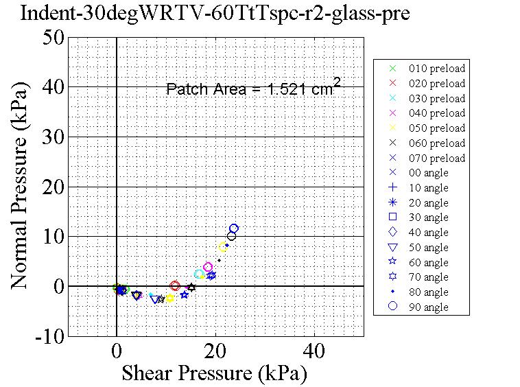
- Noe showed me how to test samples using the three-axis stage to generate a limit-surface. I would like to get a fairly accurate measure of adhesion before and after if I am going to test out different ways to post-treat.
- This particular patch had a less-than-optimal geometry which was very evident through the lackluster surface-limit that was generated in testing it.
Aug 10
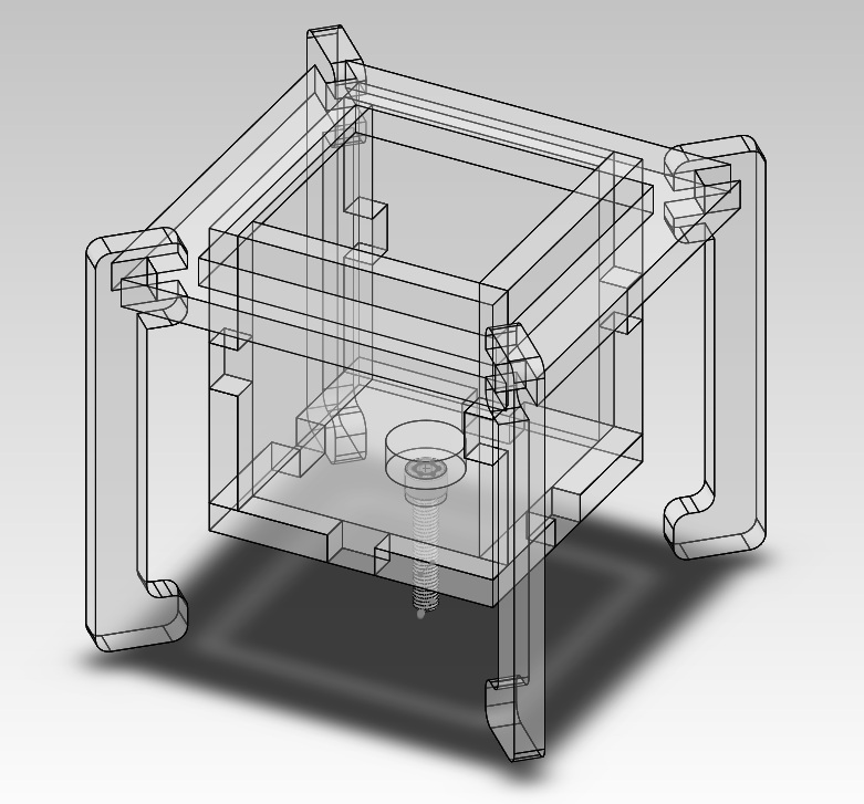
* Drew up a model, lasercut, and glued together the acryllic for a prototype of my "upside-down U-joint" to post-treat with
August 12
- Adhesion meeting
- Paul suggested the possibility of using a fine-pitched screw if I want to post-treat without the rig. This sounds like a good suggestion that would be fairly straight-forward to implement.
- Playing with the exposure time of the higher-resolution microscope camera will solve my problems with it being too dark--should have thought of this before.
- Paul also suggested that resetting the angle using the angle on our adjustable fixture is not always very accurate, I may want to vary the trajectories of the indentations by +/- 1 or 2 degrees since it can be sensitive to this.
- Took Paul's suggestion and tried to indent while varying trajectories by +/- 2 degrees of the values that I thought I should be running.
August 14
- New, quality indented patches from the HAAS! I took some measurements and pictures.
- Interior angle of 27 degrees
- Center-line angle of 56 degrees
- Height of 82 microns
- Tried to test these with the procedure on the three-axis stage but the program kept freezing on me, I'll wait until Noe comes in on Monday
August 15
- Spent the entire day trying to test the HAAS-indented patch cured onto the backing, however these tests do not seem to be performing well. The test is almost certainly failing somehow. This is intriguing since they seem to load well against the glass wall in lab.
- Thoughts: Could be this misalignment (between the stationary plane and the top of the patch) on the testing stage? Even Noe aligned the stage and was not able to get a great alignment--the patch mashes in the center before anywhere else, which is unusual. Usually it is a corner that is sticking up. This discrepancy is probably because we are not supporting the complete area of the backing. The aluminum block it is mounted on is smaller than the patch.
August 16
- Looked at the wedges that I had indented last week, trying to vary the angle and see if I could hit the correct trajectory did not seem to work. I've tried everything that Noe, Paul, and Eric have suggested to troubleshoot the Levil. At this point I think that the most-likely source of error is something I am doing in setting up the alignment, lubricant, or blade clamping. Human error. I would want to bring Eric into the LFL with me and watch my procedure closely. Another possibility is that the wax fixture could have degraded since Eric was able to produce his pristine wedges on the Levil a couple months ago. I have not gotten a quantitative measure on the deflection of the wax fixture and part of the yellow wax is separating from the blue wax on one side. I think this may be my last attempt at indenting; our efforts on the HAAS have proven to be more successful.
- Tested the un-treated patches via an Elliot-style hang test. I was able to coax the patch to hold 15 lbs and it exhibited somewhat of a pull-off angle, about 10 degrees (no guarantees on this being an accurate measurement since I was using a paper-scribed protractor).
- There is actually some creep to 15 lbs, so if it is left for awhile it tends to fall off.
Aug 17
- Attempted to post-treat a patch with the fiber-glass backing on it but it failed. The patch came out very mashed--but in a way I hadn't seen before. Comparing it to previous forces I recorded for smaller samples, this patch should have been able to be loaded to a higher force before mashing appeared. I loaded this one to 35 N. The mashing also appears in the middle and is not a uniform area--it looks like a big transition zone where areas are mixed in with unmashed areas.
- Maybe the aluminum plate needs to be flattened?
- Maybe I didn't center the point where the universal joint contacts the plate well enough?
- Loading these patches in shear against the vertical glass wall seems to be working fine, but aligning the two planes (wafer surface & top plane of adhesive) on the three-axis-stage is problematic. Interesting to think about.
Aug 18
- Spent the day collecting experimental data of the force readouts while varying indentation angles. This will allow us to see whether our process matches up with various theoretical models, even if it's only qualitatively. I indented at 60, 45, and 30 degrees from horizontal.
- I combined this with another experiment, clamping two planed pieces of wax together and indenting along this seam so that I can look at the profile of the wax without having to worry about edge effects.
- I was able to look a bit at the force data and the wax profile of the indentations I made. Imaging the wax does not come out as clearly as I had hoped that it would, the problem seems to be that it is not extremely planar so it is hard to focus under the microscope.
Aug 19
- Adhesion
- Paul is going to make a Matlab script to extract all the relevant force data and an Excel sheet to compare the predicted forces with our experimental forces.
- I need to check out to see if I can get Rowe & Spick's article photocopied at MIT and sent here
- I should look at John's fine mesh for etching gridlines onto the wax. It could be used as a stamp or a mask if it's the right size. Another option is to use a fabric that will absorb some type of particulate, then press it into the wax (in the hopes of the particulate sticking). I don't have a firm grasp on how I would successfully do this yet, but Paul threw it out there as a suggestion.
- Presented with Michela at the BDML group meeting.
- Spoke to Noe about the problems I've been having with post-treatment, we discovered that the back of the fiberglass backing was significantly warped; it would wobble on the table if closely inspected. This means that when I press on it with the rigid aluminum backing I am not getting an evenly distributed load across the face of the adhesive. Two options:
- Put the universal joint to contact directly on the face of the fiberglass backing
- Air bladder to conform to the asperities in the backing and provide and even load
Aug 20
- Failed at making a sealed cushion out of a plastic bag to use as an air bladder :(
- Looked into loading patches with the universal joint directly contacting the fiberglass backing (in other words, did away with the rigid aluminum plate it used to rest on). This just caused mashing in the middle. The fiberglass isn't stiff enough and this is a bad idea for post-treating.
Aug 21
- Sanded down the fiberglass backing in hopes of minimizing asperities/warping and was able to get it reasonably flat. This seemed to help, I loaded the patch until I saw the onset of mashing. This happened at 21N, which is lighter than last time. Something interesting happened. The post-treatment was uneven (as described below) and seemed to ruin the force distribution of the stalks when loaded against the wall.
Aug 22
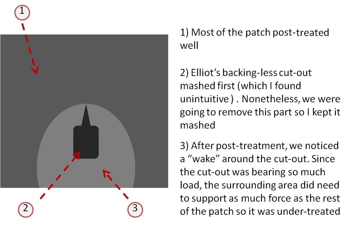
- Removed Elliot's cut-out and tried a "light" post-treat of 20N, where the onset of mashing first appeared. This sample came out under-treated. As this was our third failure to post-treat, Elliot decided to wire up the patches to his paddle un-treated.
- Current Theory on Post-Treatment: since the back of the the fiberglass is noticeably warped, this means that the front is most likely warped too. This is significantly different from what I've post-treated in the past. Even if we flatten the back of the fiberglass, the front of it may still cause the stalks to be loaded unevenly. This is the best explanation that the results thus far have lead me to.
- Tested the paddle with Elliot. It was able to hold 70 lbs. We did not want to go past this for fear of damaging the vertical glass demo wall in lab.
It is a good sign that the paddle can hold 70lbs
Aug 23
- Gave another presentation to my summer program that is funding me. It went well
- Finally updated my wiki using the notes I've been keeping in my lab notebook, long overdue :(
- Tested the paddle again with Elliot. We were able to load it to about 85 lbs, but stopped because the scale we were using kept turning off--the paddle didn't actually fail. I started with one foot on the scale to measure my weight (140 lbs) and gradually shifted weight to the foot strap attached to the paddle.
- Best idea I have to successfully post-treat with these uneven backings: utilize Elliot's tendon to load the stalks down to cure. Since loading with shear seems to evenly load the stalks, this may work. It would certainly load the stalks in a way that is more similar to what we see in climbing. The only flaw in this plan is that it relies on wetted stalks to adhere to a wafer. I should just spin a thin coat of PDMS and experiment with it.
- Status of my search for a way to imprint a gridline on wax
- John's mesh, the DPI of the laser cutter, and the DPI of inkjet printers are ruled out as options since they are not of high enough resolution (a dot or line every ~10 microns)
- Kim has transparencies that are the correct resolution. Noe suggested using a UV curable ink and selectively polymerizing it with this mask. I like this idea. I had actually done something similar at my internship at Xerox (I should have thought of this). Uncured UV ink is a pain to deal with, but I think that this could work.
Aug 24
- Took a tour of Gerdes' lab. I thought we would just sit in their room full of computers but we got a tour of the engine room and VAIL so I got to see a bunch of impressive cars (P1, X1, and Sebastian Thurn's Stanley)!
- Set up an experiment to see how well silicone rubber bonds to rastered fiberglass (rastered on the laser cutter). Silicone seems to stick pretty well to the side of Elliot's fiberglass backings so maybe this will work.
- Tried to see how well the adhesive would hold up under a shear load after dipped into a thin layer of PDMS. It felt iffy. It didn't slip, but I think I felt some creep as I loaded it with my hand. This gives me mixed feelings about post-treating under a shear load. I don't have a better alternative so I may just try to go with it.
- Tested the paddle again with Elliot. We hung! Awesome.
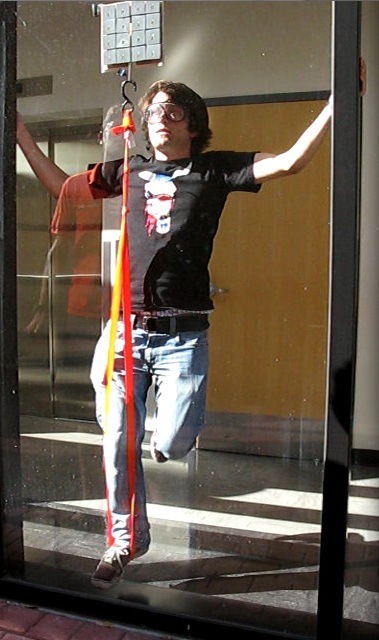
The paddle was able to hold all 140 lbs of me. I am using my hands (no thumbs in contact) to brace myself from falling backwards since it was awkward to stand in the strap (so no vertical force). It can look a little ambiguous if my foot is touching but notice the shadow of my foot on the ledge near the ground. I hung there for awhile, then tried to take my hands away and hold onto the orange webbing. I did one hand, then carefully brought my second hand over but the paddle came off and broke some acrylic in it. Either the pull-off angle caused it to detach, or the yellow "spider-wire" caught on the back of the paddle and made it peel, we're unsure. We have video of all this.
Aug 25
- Looked at the rastered-fiberglass experiment I did yesterday. No bueno. Rastering the surface of the fiberglass is not a replacement for primer, which is not surprising.
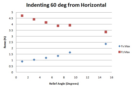
- Indented on Paul's rig and varied the relief angle (the difference between our trajectory and the face of the blade) I increased the relief angle in hopes of hitting a transition where we would switch from cutting with both sides of the blade (which may be why we are seeing forces qualitatively different than our models predict) to the tip. Unfortunately, no transition happened. Ft is still greater than Fc when it should be the opposite if we are machining like Merchant theoretically models. All the force profiles looked qualitatively the same but the magnitudes scaled consistently (see the Excel plot).
- I had videotaped one instance of indenting and it looked like the wax was still moving a bit, even though I had secured a sizable piece down to the glass with machinist's tape. This could be a source of error. Lubricant is also unable to really saturate the wax since it is oriented upside-down, although there is a consistent glob around the interface between the blade and the wax.
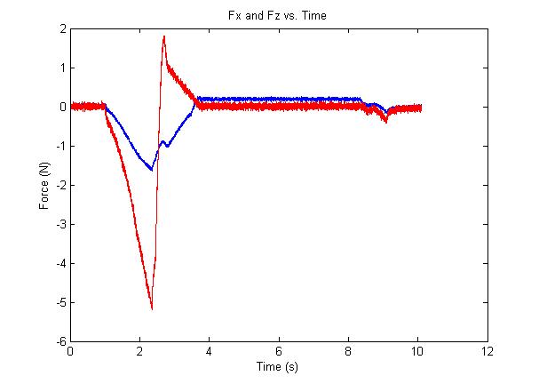
Forces at 60 degrees. Reposted from before, just to give a reminder of what the force profiles look like qualitatively. See below for the quantitative scaling as it varies with relief angle
Aug 26
- Going to Friday's meetings then driving down to L.A. before departing back to school. Thanks for the great summer!