Friday August 29
Last day of the SURI program, the summer sure seems to have gone by pretty quick. Today was mainly dedicated to tying up loose ends. I showed my dad around the lab this morning, then on to lab meeting and the SURI poster session. It was great seeing the immensely varied work that all the undergrads in different labs have been working on.
Thursday August 28
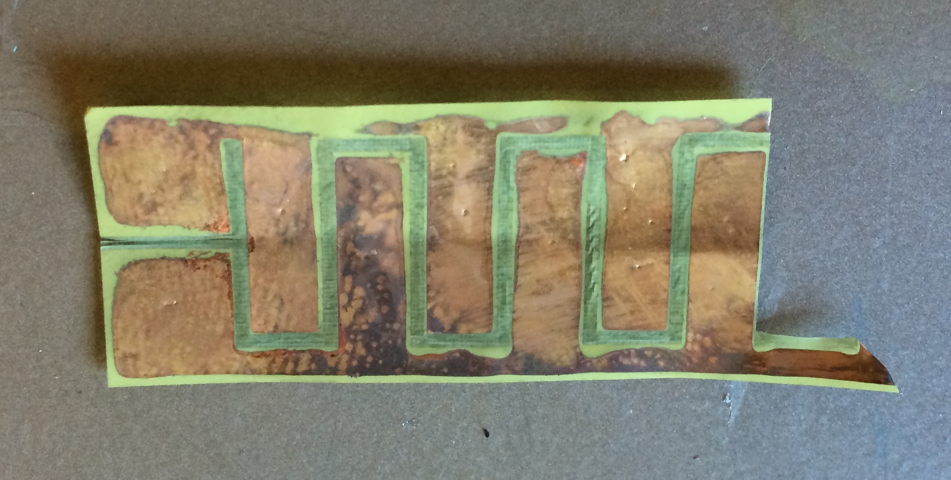
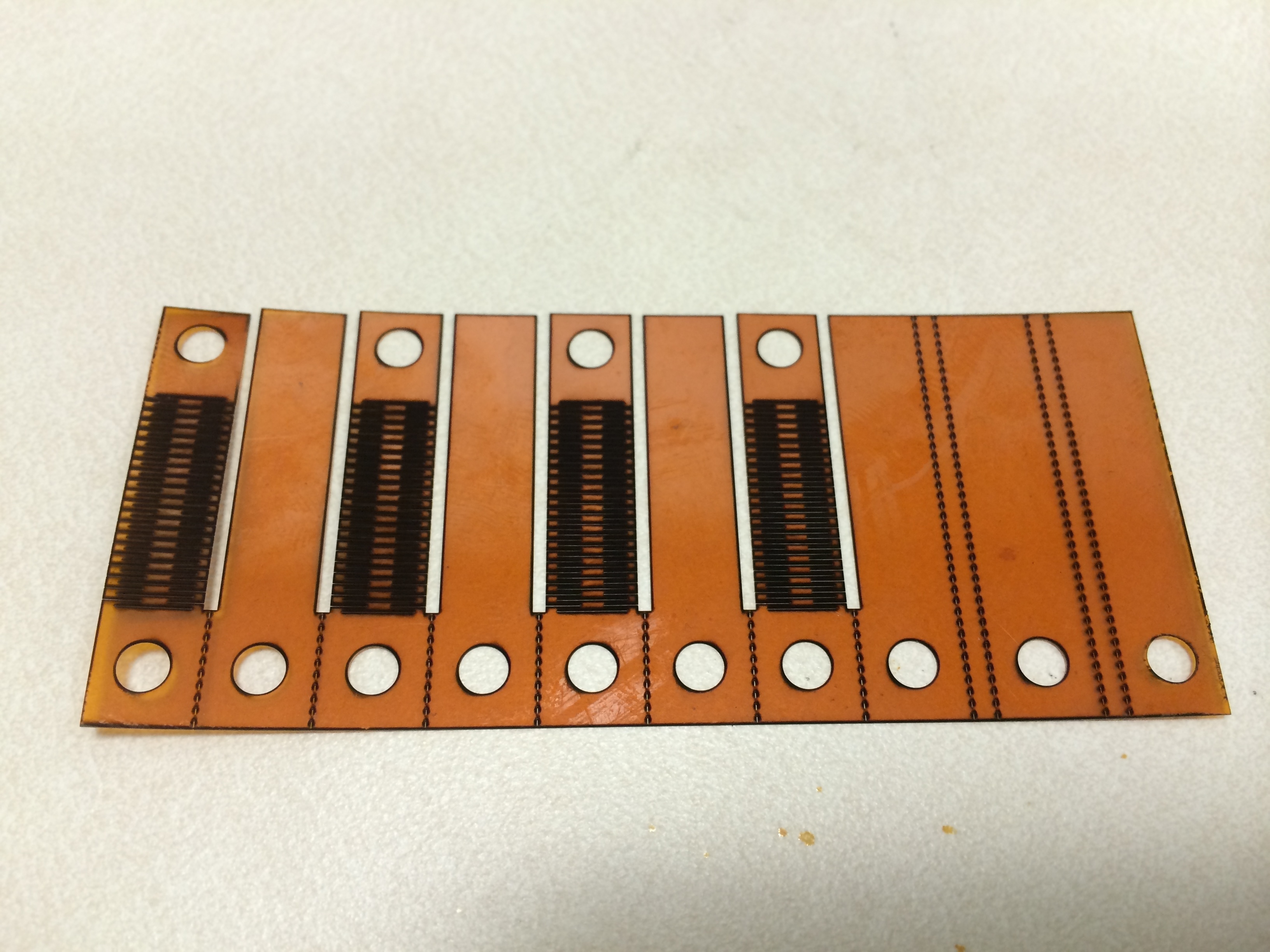
Picked up my SURI poster, and wrote my 2 page SURI reflection. I also made another electrode, this time with small perforations (200�m diameter holes in a 1mm grid) to help bond to the PDMS. Since I'm leaving soon, I thought it would be a good idea to record exactly the steps that I take to make the patterns.
Manufacturing process for etched electrodes on thin copper coated Kapton (CCK)
1. Mount the film to a glass slide
- put on gloves now, because the copper blemishes easily and you'll need them later for etching
- the sample Pyralux AC is stored next to the CNC under the Kapton film tubes in a flat sheaf
- pick a substrate & attachment method (I've been using a single glass slide and removable double-stick tape)
- cut a piece of CCK film to fit the tape (not the slide)
- put the tape on the slide, then the film on the exposed tape, being careful to not wrinkle the surface
2. Mask the film
- get some scrap cardboard/other material big enough to spray paint
- get some spray paint (I use blue because it's easy to see when the copper is covered/uncovered)
- take it outside and thoroughly cover the copper (it's ok to get it on the glass)
- wait ~20 minutes to dry
3. Ablate electrode pattern with laser
- check for more details
- I've been using the Winlase file "CCKaptonThinElectrodeD" with and without perforations
- fill parameters: 100% power, 30kHz, 500mm/s, 4 passes, Crosshatch, 0.03mm spacing
- through cut parameters: 100% power, 30kHz, 500mm/s, 15 passes
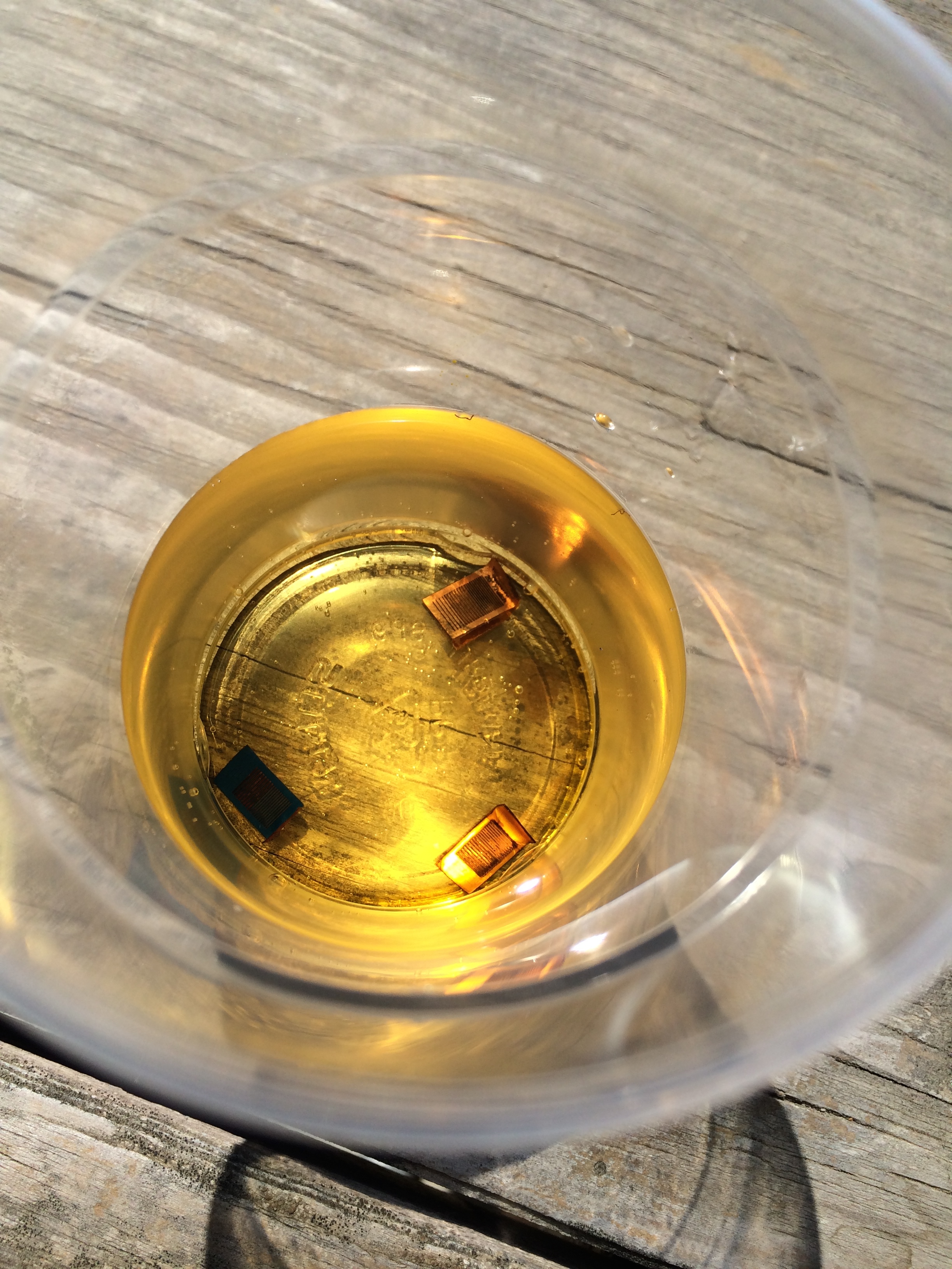
4. Chemically etch the exposed copper
- you'll need the following items (I've done this step outside):
- ferric chloride from flammables cabinet (I've been using the bottle marked "Used ferric chloride")
- two small plastic cups of water for rinsing
- a shallow tray that will fit the glass slide (helps to be clear/translucent)
- a squirt bottle of acetone
- some paper towels
- a pair of tweezers
- your gloves
- put the slide in the tray and fill ~1/4 inch deep with ferric chloride (be careful, it stains very easily)
- gently swirl for a minute or two, checking the etched pattern by holding the tray above the table and seeing if you can see through the etched areas)
- pour the ferric chloride back into the "used" bottle
- pour one cup of water into the tray to rinse, then discard water
- rinse it again with the second cup just to be safe
- visually verify that the pattern is completely etched
5. Remove the paint
- peel the excess CCK from the surrounding electrode pattern with tweezers
- squirt some acetone onto the slide while still in the tray (squirting directly onto the paint helps remove it)
- swirl until as much paint comes off as possible
- remove the rest of the paint with the paper towels, adding acetone as needed
- note: nitrile gloves don't hold up against acetone, so be careful
6. Cast PDMS
- handoff to Arul
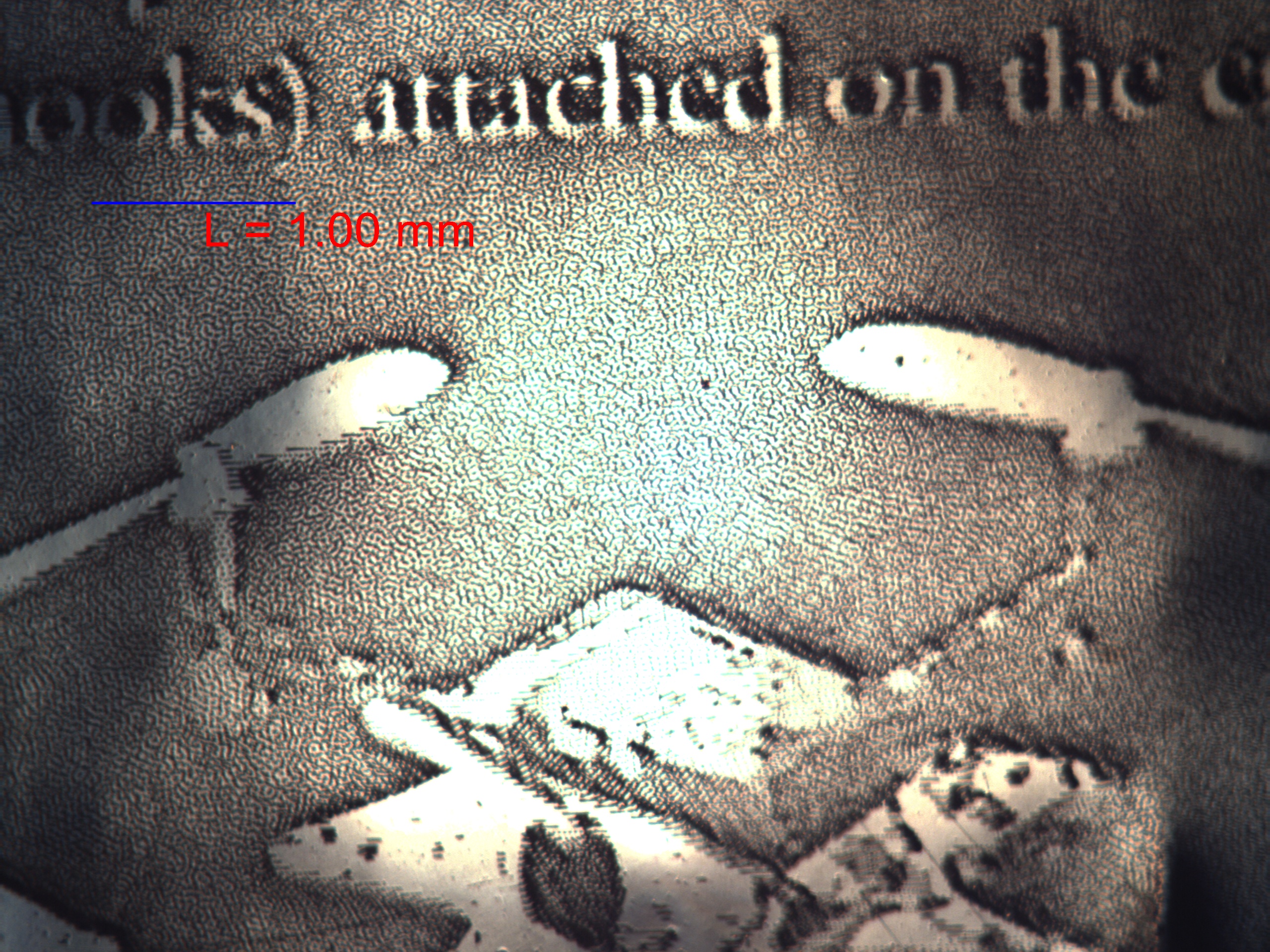
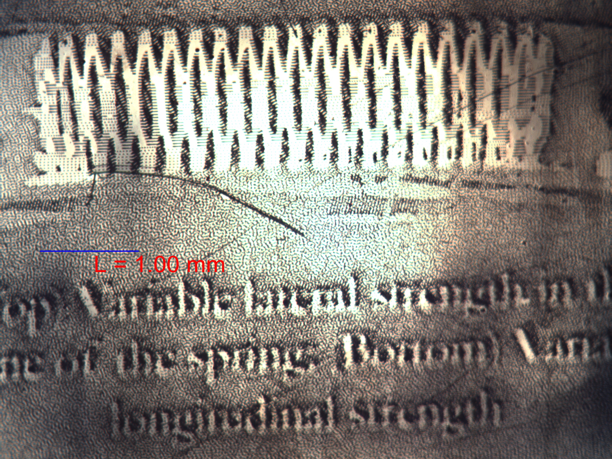
I also followed up on the laser poster idea from yesterday, with surprisingly good results. I imported a JPG rendering of the whole poster into Inkscape, then applied "Trace Bitmap" under the "Path" menu, selecting the grayscale option with 6 scans. This process gave me a separate set of vectors for each shading layer, which I could then export as a DXF to be imported into Winlase. I also had to include a bounding box with each layer because I actually want to fill in the negative area, as well as making it easier to align the objects in Winlase. When all was said and done, I had upwards of 80 MB of DXF files, and both Inkscape and Winlase lagged horribly. I could only import and cut one layer at a time because Winlase gave me an error when I tried to do it all at once. I marked on the metallized Mylar, since it would give better contrast than the steel. My only concern was whether I could get enough of a gradient, so I used 120kHz and 5000mm/s so that each pass would just take off only a very small amount of material. I used parallel fill at 0.03mm spacing, and rotated the fill by 18 degrees each layer to maintain a homogeneous fill. The end result was very good! The text is almost readable by eye, and easily readable with a magnifying glass.
Wednesday August 27
Finished my SURI poster today, and sent it off to Kinko's to be printed. Arul and Dave had the idea that I should laser etch my whole poster in an 8cm x 8cm square just for fun, so I gave that a shot. Turns out you can import JPEG files into Winlase, and it will cut a rasterized version. Unfortunately the resolution wasn't nearly good enough to work properly, but I have a few more ideas to try before Friday.
I also very carefully made a nice electrode pattern on the thin CCK, which will then have some silicone casted onto it (maybe with wedges, maybe without) so that we can see how that affects things, if at all. The trick was to attach the film to a glass slide at the beginning, and not remove it until the process is entirely finished, including casting. So far, it appears to have worked great.

Tuesday August 26
I was out sick yesterday. Today I worked mainly on my SURI poster, which will be pretty similar to my BDML presentation. I also helped Atsuo cut a thin silicone/carbon film that he's been working with (the results were very good).
Friday August 22
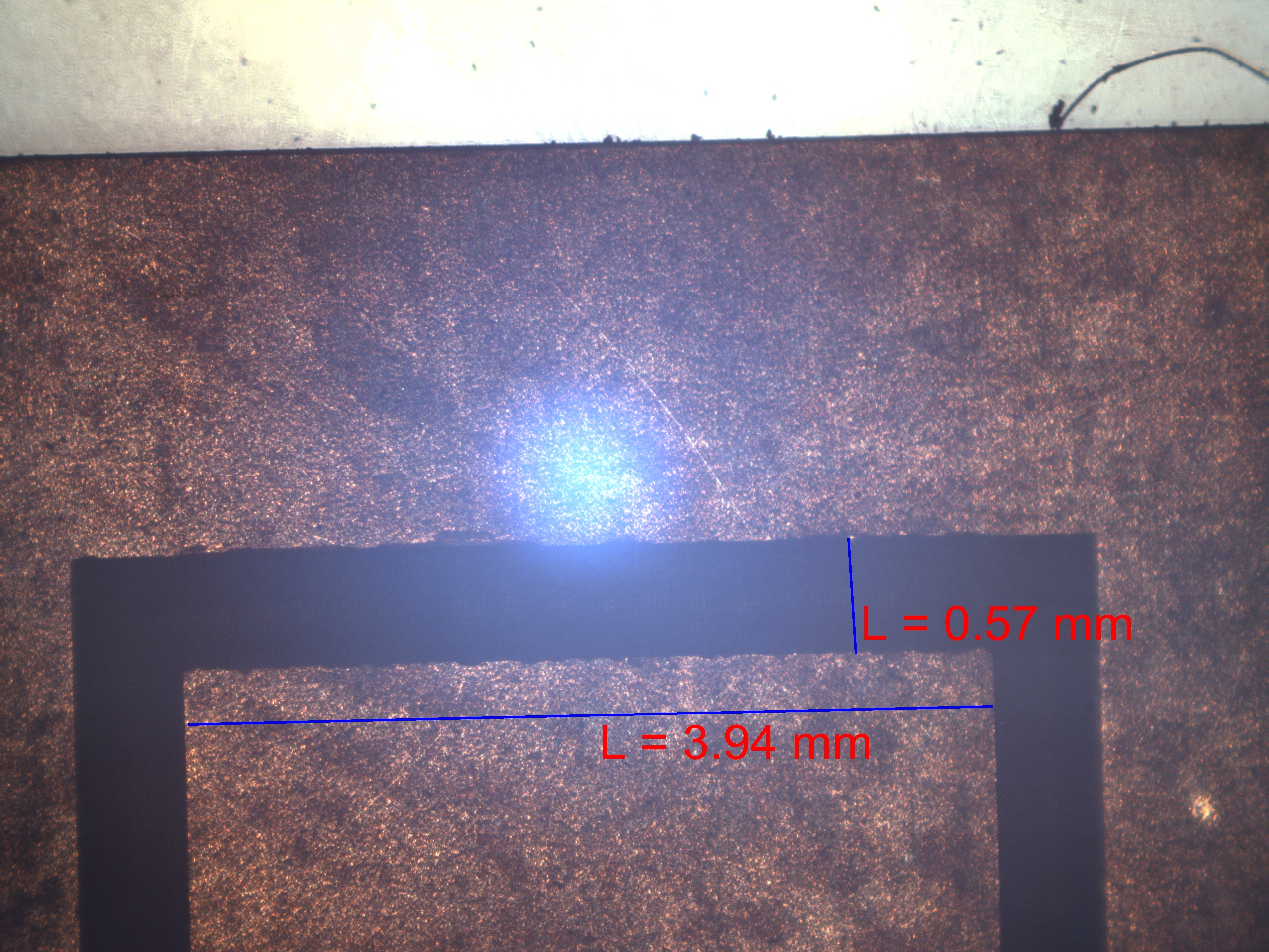
Successfully chemically etched a fine electrode pattern, and tested it with a high voltage. There was some adhesion, but the pattern with 4mm electrode width and .5mm spacing worked substantially better. Also, there was significant arcing with both designs, although the fine pattern arced earlier. Fortunately, the copper does not appear to be damaged, unlike the metallized Mylar.

Thursday August 21
Masked thin CCK with spray paint, laser then chemical etch an electrode pattern, then removed the paint. Electrical isolation while retaining the pattern. High voltage electrostatic adhesion test, observed adhesion ~3kV, more prominent adhesion on the Kapton side rather than the copper side. Attempting a finer pattern (250um spacing), we'll see how it turns out.


Left: Setup for high voltage input; Right: visible adhesion with thin CCK large electrode pattern
Spent a lot of the day working on my lab meeting presentation slides.
Wednesday August 20
Tried laser etching an electrode pattern, then applying a quick ferric chloride dip to remove the remaining copper in the etched areas. Although this method worked in some simple circular test patterns, I was not able to achieve electrical isolation on the electrode pattern without significantly distorting the original design. The new plan is to return to the spray paint masking method that I used on the thick CCK.
I also started working on my slides for Friday's lab meeting, where I'll be giving a 10 minute presentation of my summer work. This blog makes my job much easier, since I already have most of my content and pictures here already. The plan is to break the presentation into three sections: a brief overview of the DPSS laser, the electrode patterning project, and Operation Crazyflie.
Tuesday August 19
I replaced the Crazyflie landing springs, making the springs themselves slightly stronger. However, they still broke after a few tests, so I added a hard stop tendon on the remaining two spines. Morgan's been playing around with different setups on the Crazyflie to maximize success. Right now, it has a long, very weak spring (thin carbon rod) with the spines on the end, with three additional carbon outriggers in the three other directions. There's currently no damping anywhere in the system, which makes the Crazyflie jump around a lot, and often is the primary source of failure.
I also made some progress on removing the copper layer from the Pyralux CCK. The ferric chloride can remove all the copper in just a few minutes, and even faster on areas that already have copper ablated from the laser. Unfortunately, the wrinkling issue is still unresolved, and results in uneven cuts, so I haven't been able to get a good test for electrical isolation. In addition to the standard soap & alcohol trick, I tried attaching the corners to the slide with small magnets (Aimy's idea). It was ok when the cut pattern was right next to the magnet, but would wrinkle when further away, so probably not a good solution for an electrode-sized cut area.
It is also possible to score lines on a glass slide for very clean breaks, and to engrave an area quite deep into the slide (~90% thickness).
I've also started an outline for my SURI poster (and presentation at lab meeting this week).
Monday August 18
I resolved the laser issue! Turns out it was only the focus height, so the fix was straightforward. In fact, when I tried an etch test on a piece of Kapton, I nearly cut all the way through the glass slide as well! I was easily able to cut through the new Pyralux CCK, and did some preliminary tests removing just the copper layer. I have not yet checked for electrical isolation, but I could imagine that a solution involving chemical etchant might deliver the best results.
I switched over to cutting a new iteration of the Crazyflie landing springs, this time imitating Hao's original design with flat sheets of Kapton, instead of folding and orienting the springs vertically. We put it on the Crazyflie and threw it a couple of times with the Adept, with some promising results. However, the springs themselves are too weak, and some broke within the first few tests.
Friday August 15
Ordered more Kapton, since we ran out. There have been some issues with laser power today. I kept trying to cut through the new thin CCK without success. Retried the thicker CCK with the appropriate settings, also with no success. I called DPSS to help troubleshoot, here are some tips I got:
Notes from phone call with Jesse (service & manufacturing engineer at DPSS) on 8/15/2014
- The �laser power� setting under object properties (F2) doesn�t actually do anything
- Increase frequency to reduce power, and vice versa
- The �Minimize Laser Power� command under the �Tools� menu doesn�t do anything
- leaving the laser ON, but in CW mode (�ready� light on, �enable� light off) is ok for several days
- Winlase software help can be found under Computer -> OS(C:) -> marker -> documentation
Unfortunately I still wasn't able to fix the problem. The next step is to get a laser power meter and measure power output from the laser head, or have DPSS send a technician. I still need to verify that the focus height is correct using the glass slide method, and to check that the laser can still cut the Kapton (which worked yesterday).
Thursday August 14
Made another landing spring, moving away from the opposed gripper since it's difficult to detach. It is similar to one I made yesterday, so I won't show another picture. However, one of the designs from yesterday made it onto the Crazyflie, which Morgan is now testing with the Adept robot arm. It seems to be performing reasonably well, which is encouraging. So far, it really likes an arcing approach, so that the spines can really engage well. Hopefully Morgan will have a more complete working envelope soon.


I also iterated again on the Kapton integrated spines (which I'm now calling Spiny Spring) to put the spines in parallel instead of in series. I made this change after noticing that only the bottom spine would engage on the old design. I need to find a good way to fix the spines in the engaged position, since there is now 3 times the spring force and a much smaller spring displacement.
To finish off the day, I tried cutting the new Pyralux AC coppercoated Kapton (CCK), unfortunately without success. I went all the way up to the same settings used to cut the thicker CCK I used earlier, which makes me wonder if there's something wrong with the laser itself. Also, the laser warps the material around the cut, which has never happened with any other material.
Wednesday August 13
Made a few more cool Kapton contraptions. First, I refined the cat claw gripper a bit, so the guiding slots and support structure is stronger. I skipped the laser cut spines altogether and went straight to the fishhooks, and the result turned out pretty well.
Then I moved onto an opposed gripper design, which would hopefully enable successful perching when approaching normal to the surface, instead of dragging it along. I also tried adding thin strips of Kapton as a compressive spring to provide a slight preload. Unfortunately, neither of these design attempts worked at all. However, you can get a decent grip by applying a quick down-up motion when on a vertical surface.

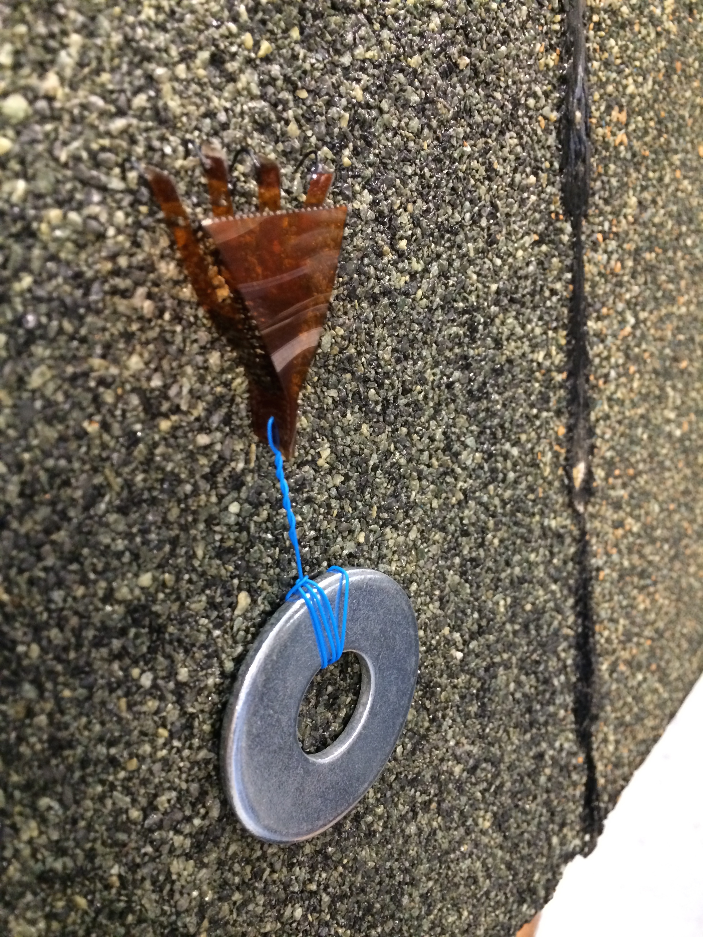
Finally, I iterated again on my laser-cut Kapton spines, this time adding a support structure from folded Kapton. What I think is especially neat about this one is that I've managed to incorporate three distinct and fairly disparate features with one material and one cut (spring, spines, and rigid body support). Adding a load, Morgan and I verified that it can grip the roof tile surface, but not very reliably.
Tuesday August 12
Made some new iterations of landing springs (takes ~2 minutes to cut), attached 4 laser-cut spines (took ~60 minutes to cut). It looks like the fishhooks are actually better, since they have a farther reach, and are much faster to cut/attach.

This picture was taken after the spines had been removed to be attached to a new spring design.
In other news, the Pyralux AC sample finally arrived. It's super thin!
Monday August 11
We had our weekly perching meeting, where I got to show off my Kapton springs and laser-cut spine, as well as get some new ideas. Some new directions I wanted to take were to include Kapton spines on the spring itself, add a preload spring component normal to the main axis, and to implement a spring constant that varied along the length of the spring. I explored all of these directions, with varying levels of success.
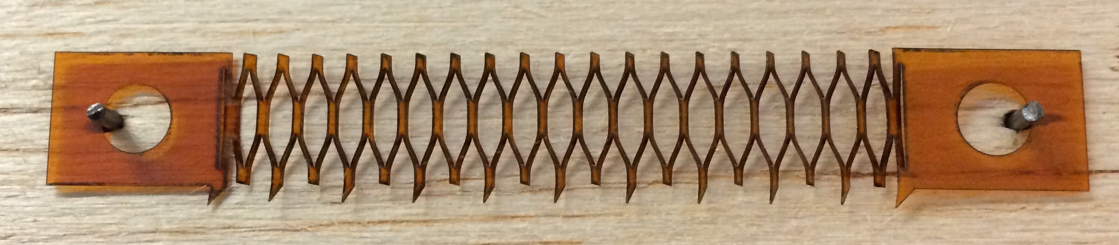
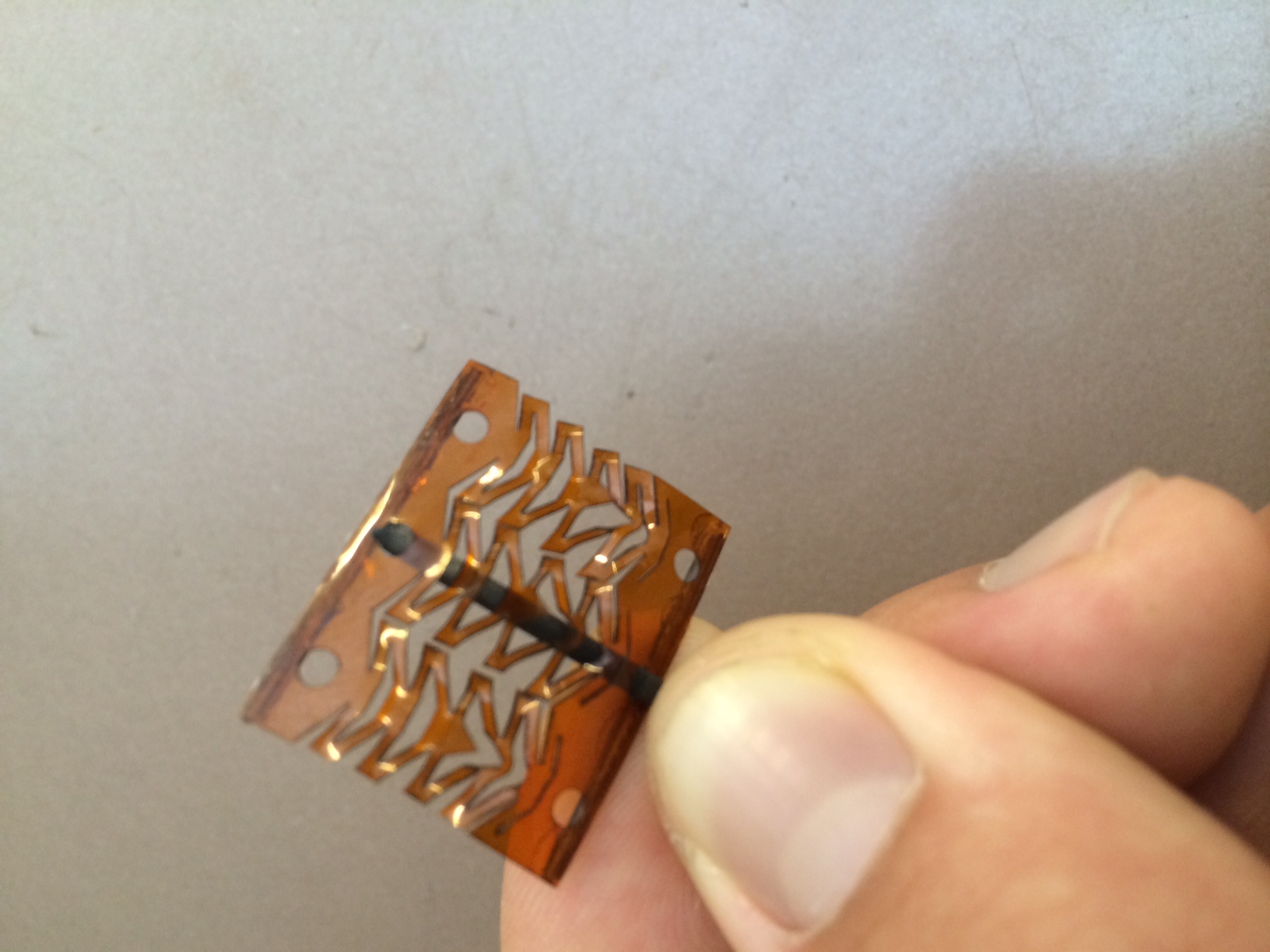
My first attempt with spines directly attached to the spring, each spine has some freedom to move, aiding in load sharing. However, the spines rotate when stretched, and aren't very strong.

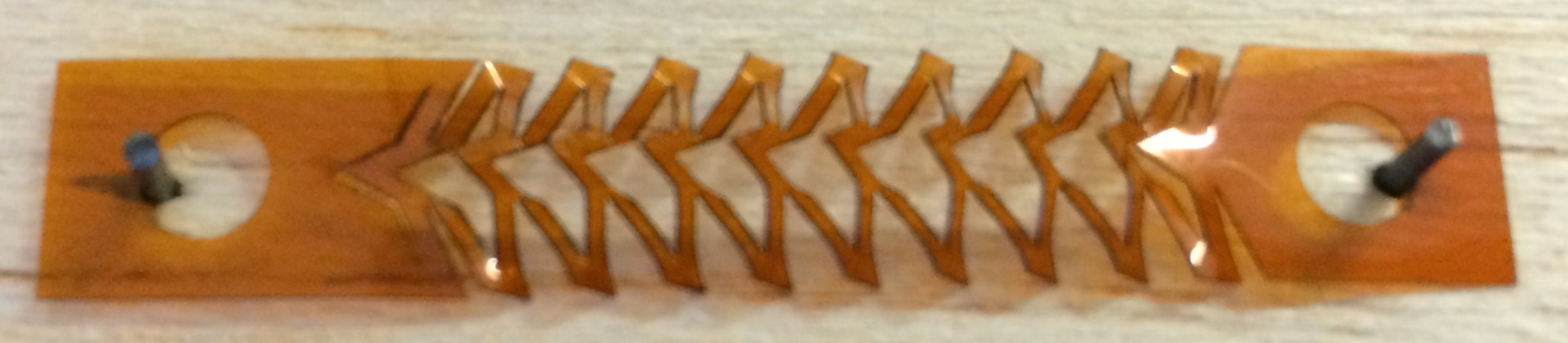
This second spine design uses rotation of the "slices" to engage the spines. Definitely an improvement, but the Kapton still isn't stiff enough to have particularly useful effects.

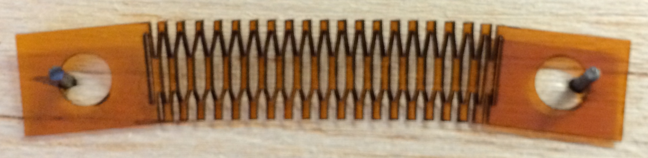
This design attempts to make one side of the spring have a higher spring constant than the other. While the effect did work, it didn't turn out to be particularly useful.

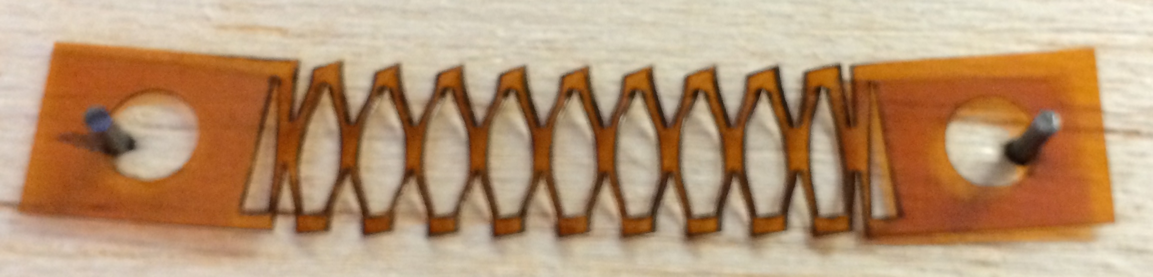
The second iteration has wedges instead of lines down the center, again to induce asymmetric effects. Was not particularly useful either.

Varying the spring constant along the length of the spring was quite effective.


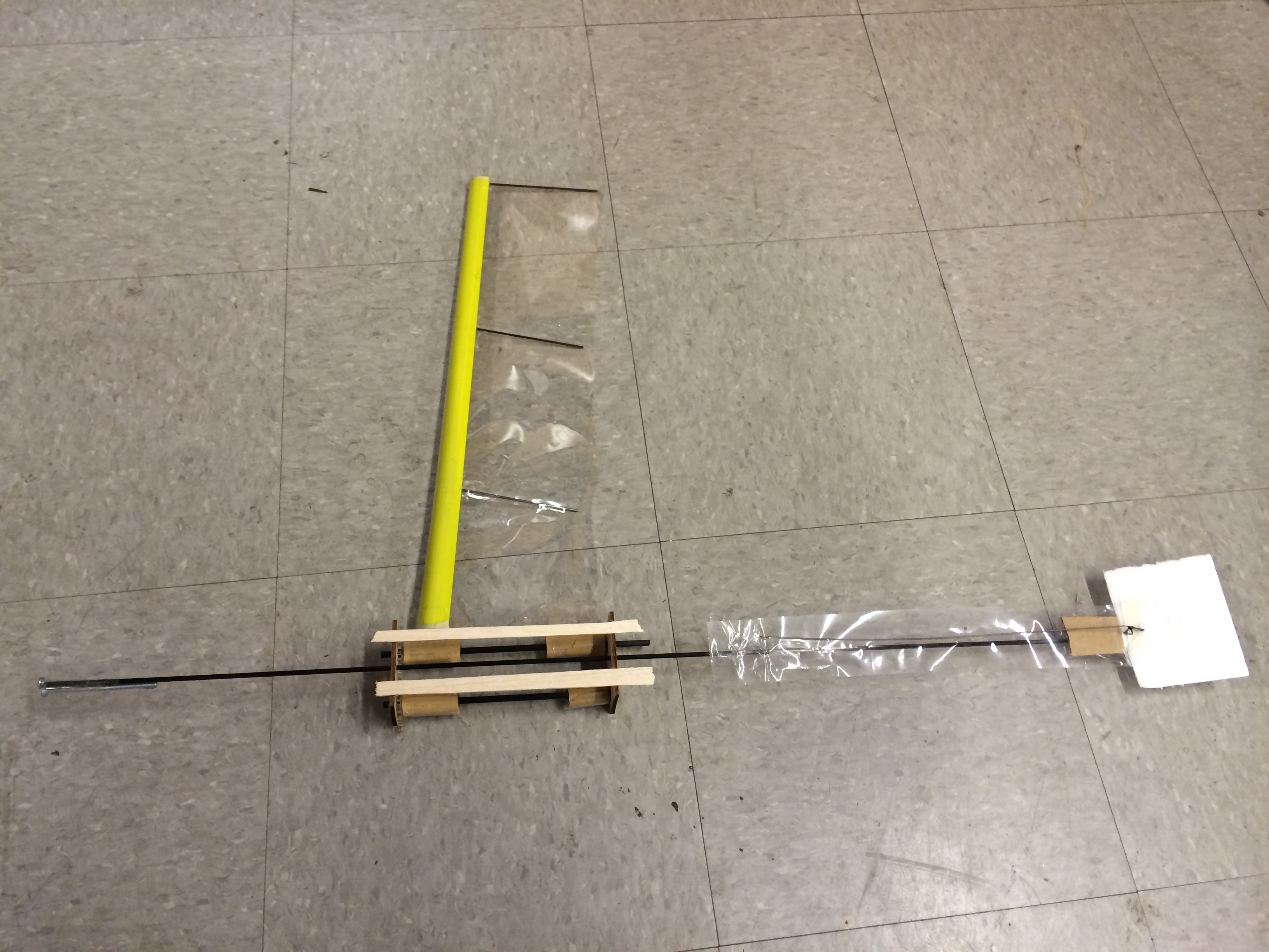
This shortened version would be used in the landing gear apparatus, to compensate for the friction in the housing, and with a long end so that the spring portion doesn't ever leave the housing.
Friday August 8
Today was Bobby's last day in lab, so he presented his work on the Crazyflie at lab meeting, and gave a tutorial on how to use the Crazyflie. Afterwards, I transitioned to working on laser-cut spines. My first attempt was too small, but the second cut (pictured below) works quite well.
2nd spine attempt glued to the end of a Kapton spring.
It's interesting to note the cut profile of these spines. The kerf on the top surface is ~100um, whereas the kerf on the underside is ~15um. That means there's a distinct slope on all edges of the cut. This is also noticeable when looking at the spine tip under the microscope, focusing on both the top and bottom surfaces.
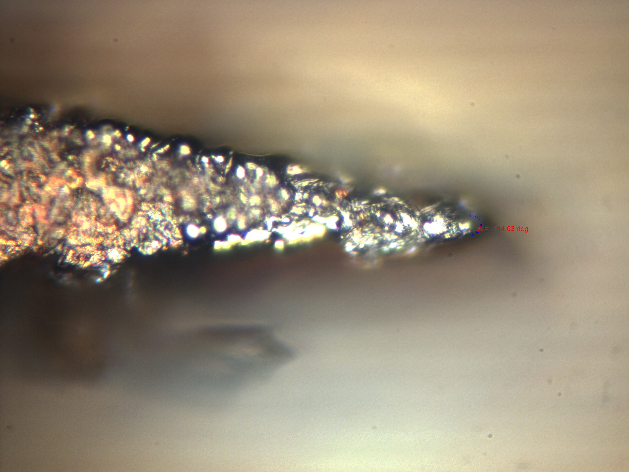
The tip of the laser-cut spine, focusing on the top surface. Radius of curvature is ~5um.

The tip of the laser-cut spine, focusing on the bottom surface. Radius of curvature is ~15um.

The tip of the fishhook currently used on the spine grippers. Radius of curvature is ~12um.
Thursday August 7
More Crazyflie struggles. Opted to switch gears partway through the day to revisit my idea of cool laser-cut geometries. As I was leaving, I ran into Elliot, who had an idea for stacking several Kapton springs, flipping them 90 degrees, and surrounding them in a protective housing, that way each spine gets its own spring. Another idea is to try laser cutting the spines themselves from metal shim stock. I tried 0.004" brass first (that's what we could find), with no luck. We looked for some steel, and I managed to get through that with some difficulty (100mm/s x 4500 passes = 45 seconds/mm). Ran out of time to try for the spines themselves, but I'll get on that first thing tomorrow.
The Kapton spring apparatus turned out quite well on the first try, and I made a second one with a few small changes. Moving forward, it's important for the spring portion of each tendon to remain fully within the housing, so that it doesn't catch on the edges when retracting. Hao also mentioned that it's important for the spines to have a slight rebound for normal to the main spring axis, so that the spines push back against the wall when they impact.
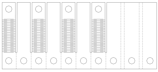
This is the Inkscape file for the landing springs. Unfortunately, this is too big for the DPSS cutting window (which is 80mm square), so it had to be scaled down ~10% in Winlase. Note that when importing the DXF into Winlase, it exists as one object, so you forfeit the ability to edit any individual features. You can still position it and scale it though.
Immediately after cutting. For reference, the holes are ~5mm diameter

Pre-creased, ready for folding.
Wednesday August 6
Tough day today. A lot of slogging through Crazyflie code, not making much headway. I'm still trying to implement an external sensor into the firmware and software framework, but I'm pretty lost. I know on a general level that I'll need to set the sensor pin to analog input, create a variable somewhere to store the data, then refer back to that variable in the UI/flight control. I've found a couple more useful posts: accessing analog sensor data through Python API and autonomous flight with external analog sensors.
I also put together a wiki page with tips and tricks for the MERL BBQ for next year's SURIs.
Tuesday August 5
Today involved lots of poking around the Crazyflie code, wiki page, and forums to get familiar with terminology and look for ways to integrate external sensors (e.g. hall effect) into the onboard controls. This challenge is twofold: 1) connect the hardware 2) implement the firmware/software. Seeing how we're already struggling with implementing software for the onboard sensors, I started looking for how to physically connect the sensor, then worry about software later. This schematic shows the places on the Crazyflie where we'll physically solder the sensor, while this forum post and this video tutorial go into the firmware/software side of things. In general, this stuff is pretty over my head, so it's been fairly slow going. There's a wealth of information for me to learn from, so I could likely eventually get something to work, but there are probably others in lab who could do the job better and faster.
I did a quick Arduino setup to verify the Hall effect sensors, and everything appeared to be in working order. We should be able to use pretty small magnets, and the total extra weight of the sensor apparatus will likely be ~.5 grams.
I also briefly helped out Dave with testing a piezoelectric sensor, which was really cool. We got some neat signals, both by connecting the raw output to an oscilloscope, and by first processing it through this coupler.
Lastly, it looks like we're going to revisit the capacitive sensing idea with the laser-etched metallized Mylar, we just need to borrow a capacitive evaluation board from one of Dave's friends.
The DuPont samples shipped today, they're expected to arrive next Tuesday August 12.
Monday August 4
Got back into the swing of things with Crazyflie perching with our weekly meeting. Bobby has successfully mapped a custom script open loop maneuver (a flip) to a button on the controller, which is a big step forward. The next challenges are to implement the open loop pitch-up maneuver, and then add sensor feedback (accelerometer, battery strength, etc). I helped for a bit looking through the existing GUI code hoping to find ways to access the sensor data. We've made some progress, but there's still plenty more work to be done.
On a slightly different note, I'm going to take a stab at adding a Hall effect sensor to the Crazyflie (specifically, this one), based on some findings that Bobby had a few weeks ago (July 16). Using a combination of an accelerometer and a flex sensor, he was able to determine whether a perch was successful with relative ease and speed. The accelerometer clearly defines the moment of impact, and the flex sensor is attached to the rebound spring. When the flex sensor stretches, then the rebound spring has engaged and the perch is a success. However, if the sensor returns to the unstretched position at any time, or doesn't stretch to begin with, then the perch failed. With some simple signal processing, the flex sensor data can be turned into a binary signal that indicates a successful perch.
As we look to adapt this method to the Crazyflie, it's important that the sensors be small and light enough, as well as simple enough to work with the Crazyflie's onboard processor. A Hall effect sensor should be suitable on both fronts, and should also have similar general behavior to the flex sensor. Fortunately for me, Audrey has been working a lot with Hall effect sensors this summer, so I read her blog to get some hints and ideas. I won't be able to start working on it until I bring my Arduino tomorrow, so I'll talk with her more then.
Lastly, I was thinking about what other cool things I could make with the laser, incorporating fine patterns that have interesting macroscopic effects, or novel folding designs. I decided to try an interlocking honeycomb pattern, which would turn an otherwise flimsy but strong material (Kapton, fiberglass) into a rigid body. Unfortunately, the initial few tries were a complete bust. The effort to assemble the structure is prohibitive by itself, plus the strength of the resulting body was not very impressive. I could probably improve the design with more work, but I feel that I should go in a different direction entirely.

Friday August 1
Bobby and I came to the lab at 7:30 to start smoking the pork loin, and the rest of the morning was an increasing frenzy of preparation. But everything was eventually ready for lunch, and we actually ran out of all meat and veggie burgers (we suspect that lots of people took two servings of pork). All in all, a great success!
Wednesday July 30
Today was BBQ planning day. Bobby and I drew up a shopping list, then went to Costco to buy $300 worth of food. To change things up a bit, we'll be smoking pork loin (with some hamburgers for the less adventurous). Tomorrow should be fun.
I also set up a shorter link for the DPSS Laser Google Doc, http://tinyurl.com/DPSSLaser, which I'll post next to the laser itself. Unfortunately, the computer there is not connected to the Internet.
Tuesday July 29
The Caswell �Flash copper� electroplating kit came today. When we ordered it, the plan was to plate the metallized Mylar with a thicker layer of copper to create a more robust conductive layer, but not as thick as our current copper clad polyimide. Although I suspect we will get the best results with the thinner DuPont samples coming soon, it is probably worthwhile to give the electroplating a shot. I think the biggest challenge will be finding a suitable space to perform the procedure, which could be somewhat messy.
Switching gears to the Crazyflie, Bobby achieved another successful pitch up and impact a wall, which we caught on slow motion video from two angles. It takes a while to test maneuvers, especially having to recharge the battery every few minutes. We also found (not surprisingly) that the battery level has a significant impact on the flight behavior, for example the Crazyflie travels roughly twice the distance on a full battery than a nearly empty one. There were additional issues with certain motors not starting right away, or not starting at all. Sometimes this indicated a low battery, but often it was just some dirt in the motor that could be blown away. I think the bumpers I made yesterday helped a bit with impact-related damage, but there�s still a slight issue keeping it attached securely but not permanently to the Crazyflie.
To wrap up the day, I went back to the laser and made some Kapton springs based on Hao�s design for the Crazyflie spine landing gear. There�s a 50um kerf on ~120um thick Kapton, and I was able to achieve ~150um wide fibers that retained a good amount of strength.


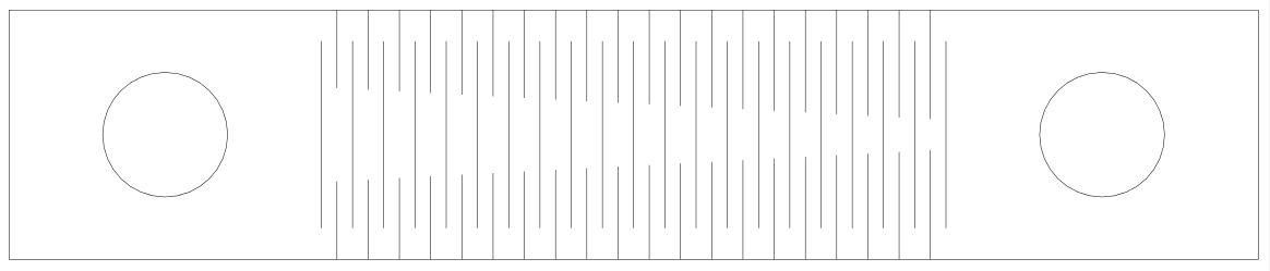
The line spacing on these springs is 500um.
Monday July 28
I spent most of today building and refining a set of detachable bumpers for the Crazyflie. They are made from spring steel wire, and attached by wrapping the joints in thin electrical wire, then soldering for a permanent attachment. The apparatus weighs in just over 3 grams, so unfortunately it can only be used as a training tool when the Crazyflie isn�t carrying anything else. On the other hand, it could help simulate the weight of the landing gear while it is being developed.

And here's our first recorded successful pitch-up maneuver on the Crazyflie!
Friday July 25
I read some papers on the aerodynamics and biomechanics involved in throwing a frisbee, which I hoped would provide some insights into building a flying disc robot. This paper gave a good overview of what I was looking for, and also provided some useful experimental data. At the point of release, forward velocity is ~10-12 m/s, and angular velocity is ~4.5-6.5 rps (30-40 rad/s). Additional papers can be found here and here.
Bobby and I also started playing around with open loop maneuvers on the Crazyflie, trying to pitch up and impact vertically onto a wall.
Thursday July 24
Pyralux AC Samples are confirmed, 4 - 12"x18" sheets
Updated DPSS google doc
found this: http://www.edrawingsviewer.com/default.htm
details on exporting inkscape files to .dxf so that they can be read by a laser cutter: http://wiki.imal.org/howto/inkscape-and-lasercutter
another inkscape DXF exporter: http://www.bigbluesaw.com/saw/big-blue-saw-blog/general-updates/big-blue-saws-dxf-export-for-inkscape.html
Wednesday July 23
I finally got in touch with the DuPont rep, and he said to just fill out the sample request form, which I did last week. So hopefully we'll get our hands on some samples soon. I also looked into installing the Aerotech PRO115 XY stage, only to find that it is too big for the laser housing in one dimension. I guess that means we'll try to return it and get a slightly smaller one. On the plus side, I was able to find a pretty comprehensive manual for the Aerotech PRO115, which is great since there was no manual with the stage itself. I finished up the day by doing some test cuts on fiberglass. The 0.12mm thickness was straightforward, but the 0.50mm thickness had some interesting results, with the vertical cuts going through, but the horizontal ones not.
Tuesday July 22
I spent most of today playing around with Inkscape with the intent to eventually be able to create designs that can be cut with the DPSS laser. I explored lots of cool capabilities of the program, and then finished up by making the same interlaced electrode design that I made on the laser software, and tried exporting it as a .dxf file. Unfortunately, it didn't quite work, as the filled rectangles showed up with borders only, and the cloned shapes that populated most of the original Inkscape file did not translate at all.
I also called the DuPont representative again to ask about getting some thin copper clad polyimide (Pyralux AC), but he wasn't there. I'll try calling tomorrow.
Monday July 21
Played around with the idea of applying a high voltage AC source across the mylar electrode pattern to potentially improve performance. With Mark's guidance, I searched for some devices that would deliver such a voltage. The most plausible ideas we found were Tesla coils, automobile ignition coils, and transformers for neon/xenon signs. Of those options, the ignition coils and sign transformers seem to be the most promising. In the meantime, I tried rigging up a high voltage AC circuit by applying a function generator to the DC-HV DC converter that I have been using. Unfortunately, once the function generator was connected to the HV converter, there was no meaningful signal either before or after the converter, and therefore no electrostatic effects on the film.
In other news, Matt and Bobby got the Crazyflie working, so I got to try flying it. It's pretty fun!
Friday July 18
some links: thin Pyralux single sided copper clad laminates
thin Pyralux double sided copper clad laminates
dupont regional representative contact info
aquamacs - text editor
Thursday July 17
Today, I focused on an entirely different technique for using the laser to print electrodes, this time on the copper coated Kapton. Since it is very difficult/impossible to etch off the copper and leave the Kapton, the new method is to apply a masking material, use the laser to print the desired pattern, then etch the exposed copper away with ferric chloride. The process of etching the copper is actually quite straightforward, so the primary challenge is finding a suitable masking material that will adequately block the ferric chloride, is easy to print on with the UV laser, and will not distort the high precision designs that are necessary for good electrode design. The first obvious choice was a photoresist film, which either exposes or blocks the underlying material when exposed to UV light. I ordered some, but unfortunately it is shipping from China and will take several weeks to arrive
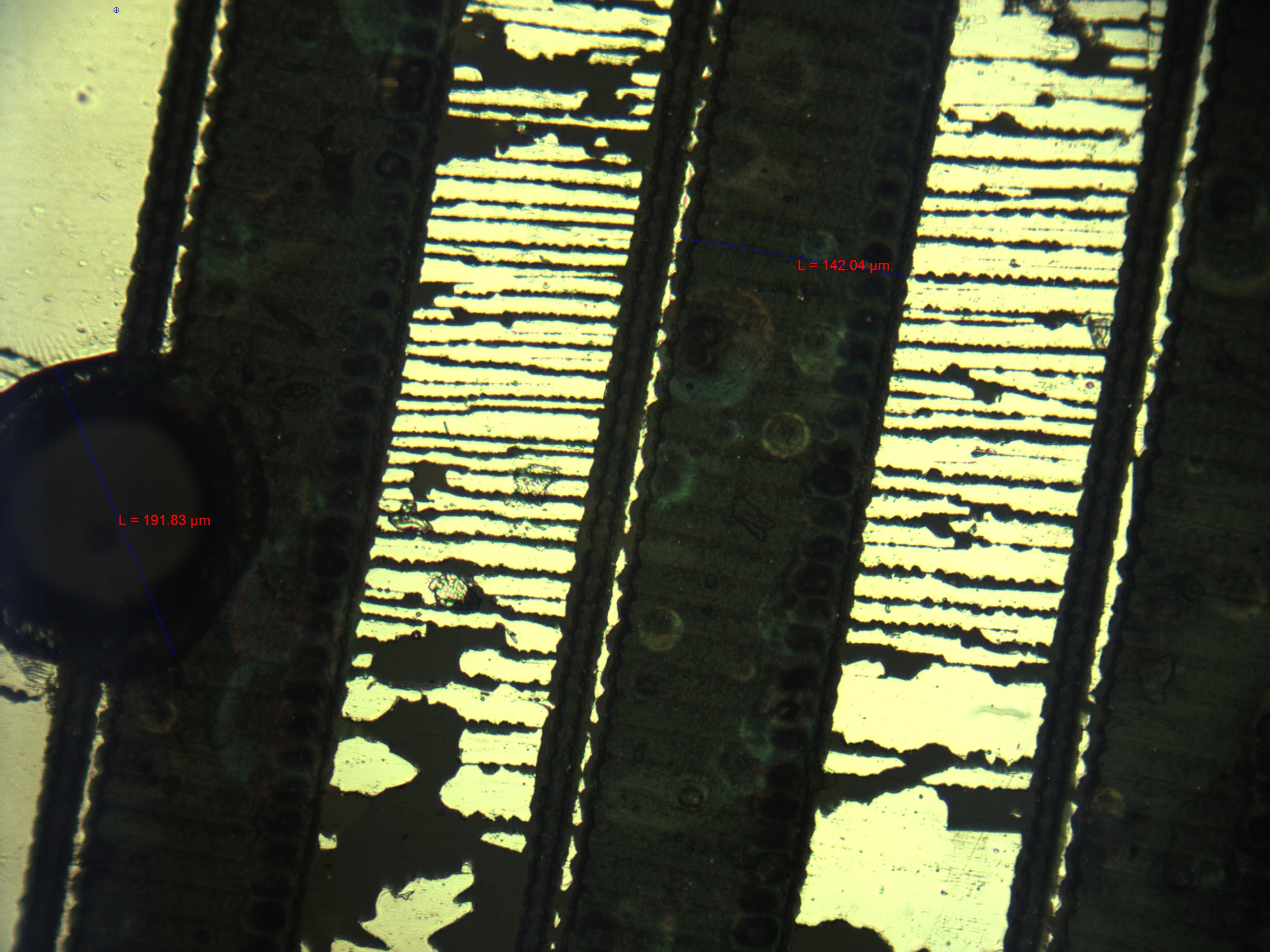
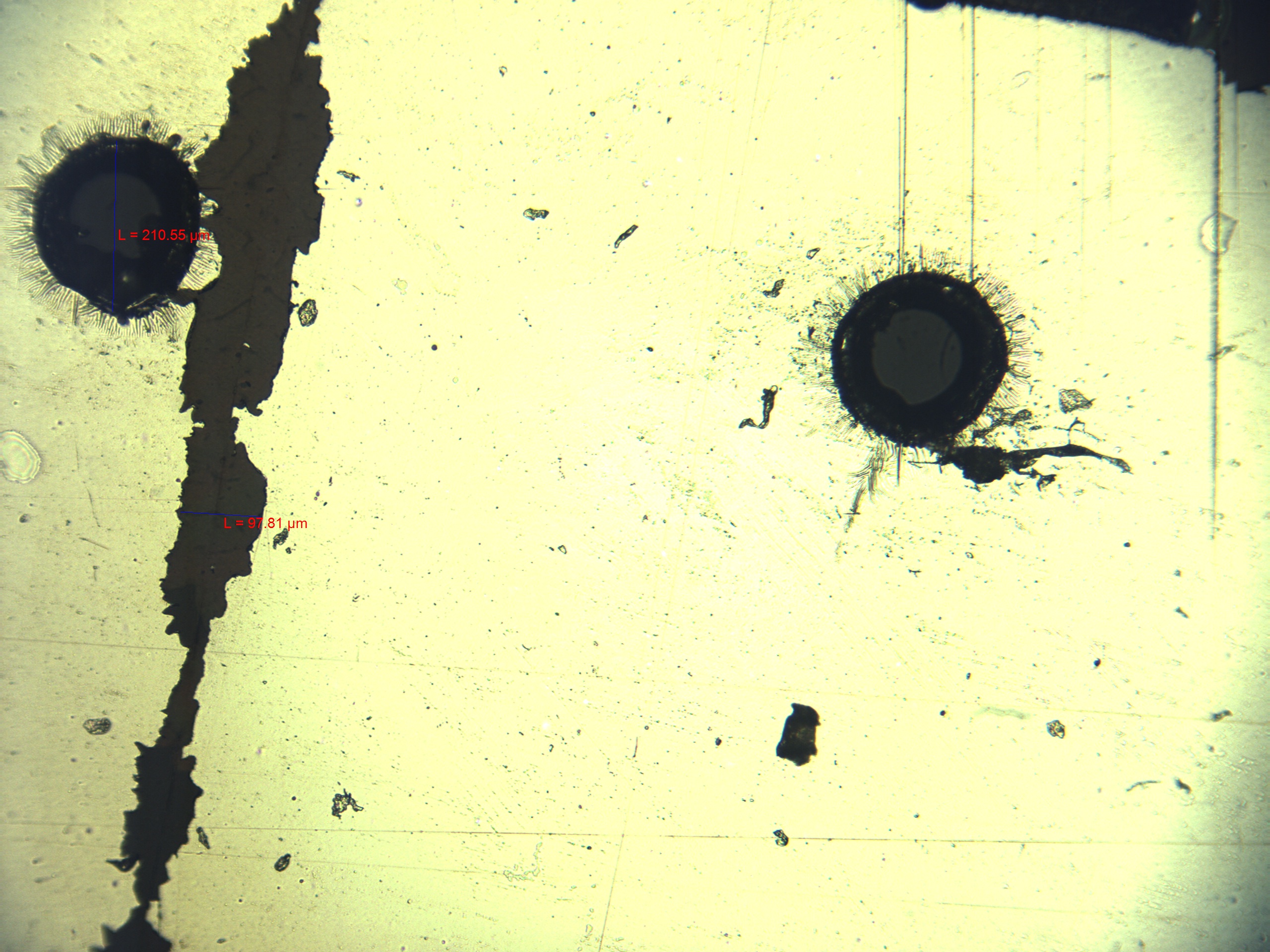
In the meantime, there are a couple of other options that I explored. First, simply spray painting the copper surface, then etching off the paint. Since the copper layer is quite thick, it is actually quite easy to expose it without damaging the Kapton. My first test went well, with the larger geometries (1-5mm) turning out very well. However, there was significant undercutting for the 100um lines, to the point where all of the copper underneath the mask was also removed. I also learned from this test that it is important to put the samples in the ferric chloride solution horizontally, otherwise it will etch unevenly and distort the laser printed pattern.

For my second test, I changed my pattern to have larger gaps (200um), and used two additional masking materials along with the spray paint. Arul had previously made two samples: one with a clear spray-on acrylic coat, and one with Kapton tape. After etching the same pattern on these three masking materials, I found that the two spray-on masks performed the best, primarily because they maintained a good bond with the copper and prevented leakage. Although there was still undercutting, the increased cut width kept the copper slivers intact. This issue could also be improved by using a Kapton film with a thinner layer of copper.
Wednesday July 16
Finally got a good electrode pattern that gave good adhesive results. After reading this paper that explored the effect of electrode geometry on adhesion, I cut a pattern with 0.5mm gaps and 4mm electrodes. This design yielded consistent positive results, with noticeable adhesion at 1kV and no damage to the film until ~1.5kV. Dave and I took a couple of nice pictures, then checked some of the old films for capacitive sensing. In theory, the measured capacitance across the electrodes would increase with the presence of some object, like a finger. We were able to see this effect very slightly on the rough pattern from one of the first patterns.
Tuesday July 15
Continue cutting and testing electrode patterns. At the beginning, I got similar results to yesterday, but then after switching to another film, I couldn't recreate the same behavior. Dave and Mark came to help set up a circuit (add one 20 MOhm resistor in series) so that we could determine what current we were putting through the film, which was between 30 and 250 nano Amps, depending on how the film was connected. We saw some curious phenomena by connecting just one electrode, one electrode and grounding the attraction test piece (acrylic), and both electrodes on the same voltage while grounding the test piece. Altogether it was an interesting intellectual exploration, but not very helpful because we are no longer getting the behavior we want, and we're not really sure why.
Monday July 14
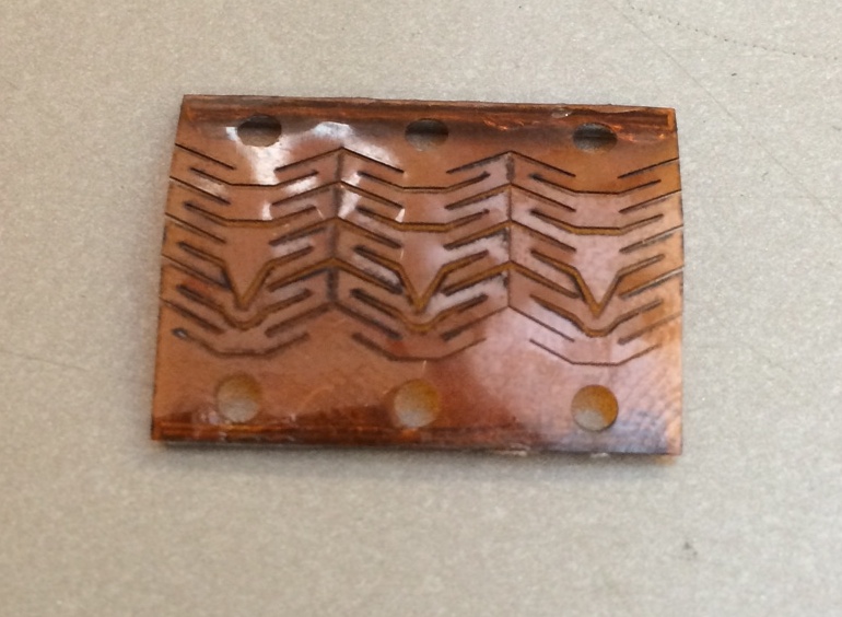
I tried another iteration of the electrode pattern, changing the outer dimensions slightly, making the fine pattern 150um spacing instead of 100um, and adding attachment areas for all four electrodes at one end. I also added in an array of 100um diameter holes to help bond to the PDMS. As it turns out, Arul returned later today having successfully bonded to the old etched electrode pattern, so it would appear that the holes are unnecessary.
The fun part came when I tested the film with a high voltage source (2-4kV), both the rough and fine patterns. I was able to achieve electrostatic attraction with both patterns, although at the higher voltages there was significant popping, which I assumed to be arcing. Visual inspection showed damage across the conductive portions of the electrodes, perhaps due to micro fractures in the metal layer before testing.
Friday July 11
I designed the adhesion/sensing electrode pattern and printed a couple of iterations, and we'll test them at appropriate voltages next week. I was able to get the sensing electrodes/gaps very tightly packed, at 100um.

Thursday July 10
I tried more cuts on the copper coated Kapton, this time using two lines with a slight offset. Under the scope, the cut width was in fact wider, but it was still conductive. I also tried cutting across one of the cuts to check the cross sectional profile, but due to deformation from the Xacto knife and unevenness in the surface, I couldn't get a clear image. In the early afternoon, Arul brought back a successful casting that bonded the PDMS to the metal side of the Mylar, using the same primer as used to bond to Kapton. Interestingly, you can quite easily peel off the Mylar layer, leaving the "gold" side exposed (we're not sure exactly what it is, but it doesn't appear to be conductive). This is a promising discovery, and it would be far easier from a laser etching standpoint if we could use the Mylar instead of the copper coated Kapton.
The next step is to try etching an electrode pattern that can be used for electrostatic adhesion/sensing. The easiest way to start with is an interlaced "fingers" approach, with varying electrode and gap width based on whether it is a high (adhesion) or low (sensing) voltage application. Unfortunately, I got sick in the afternoon and had to go home before I could get started.
Wednesday July 9
Today was more laser experimentation, starting with trying to print resistors. Unfortunately, my first attempt did not work, although I used identical settings that gave me a ~150Ohm resistance yesterday. Also, I remeasured some of my patterns from yesterday, and found some significant resistance differences. This discovery prompted me to give up on the printed resistor idea, at least for now.
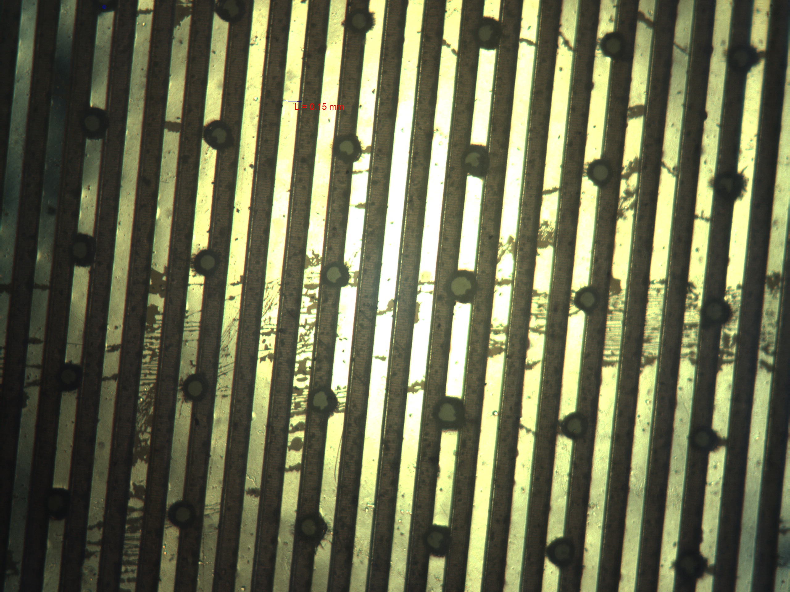
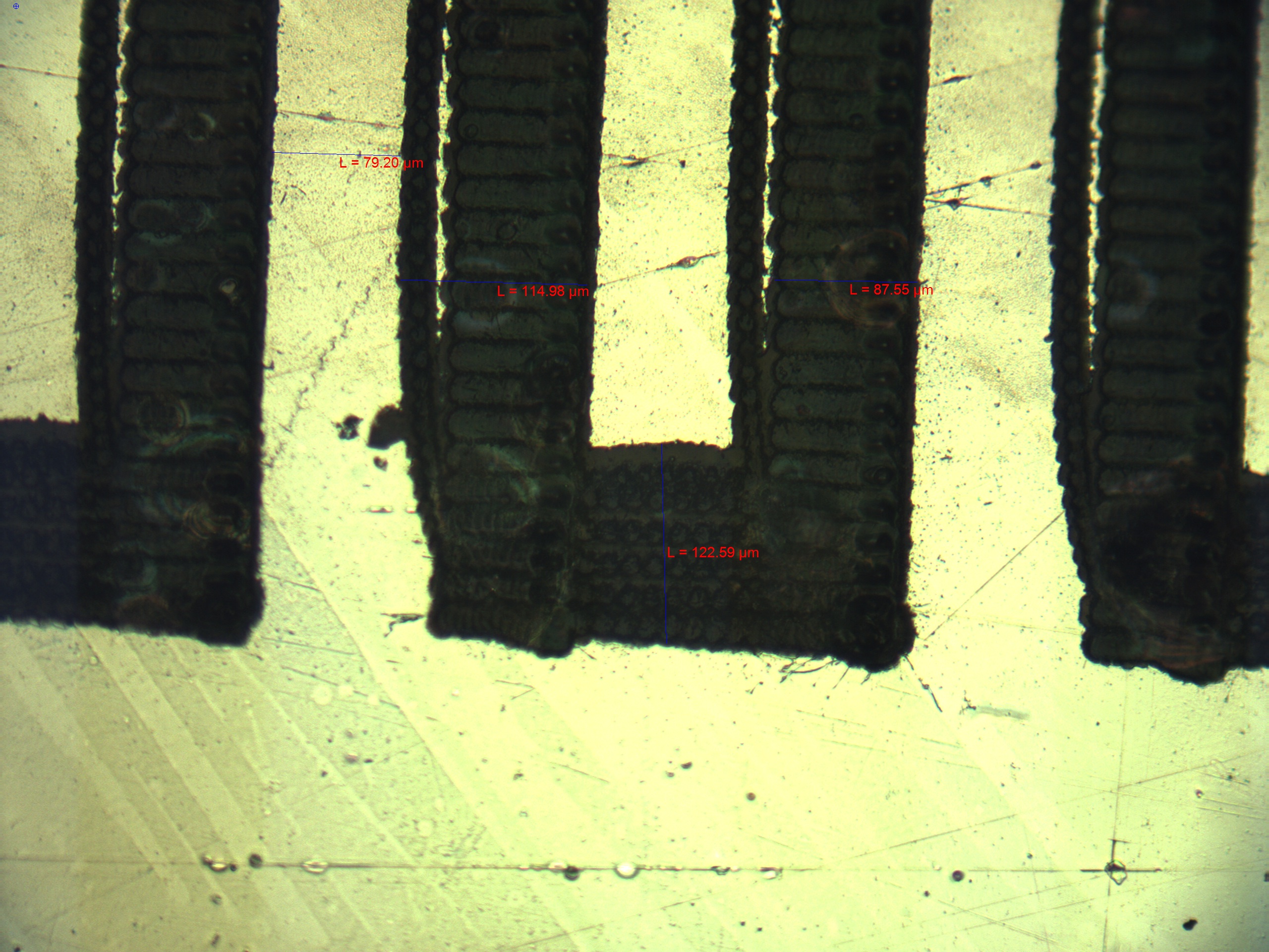
Next, I took some nice microscope photos of the fill patterns and line cuts. Figures 1-4 show how the pattern changes when varying offset angle, cut speed, and cut power. Note the meta patterns that arise, especially in Figure 3. Figures 5 and 6 show the difference between high and low frequencies, namely the width and cleanliness of the cut.
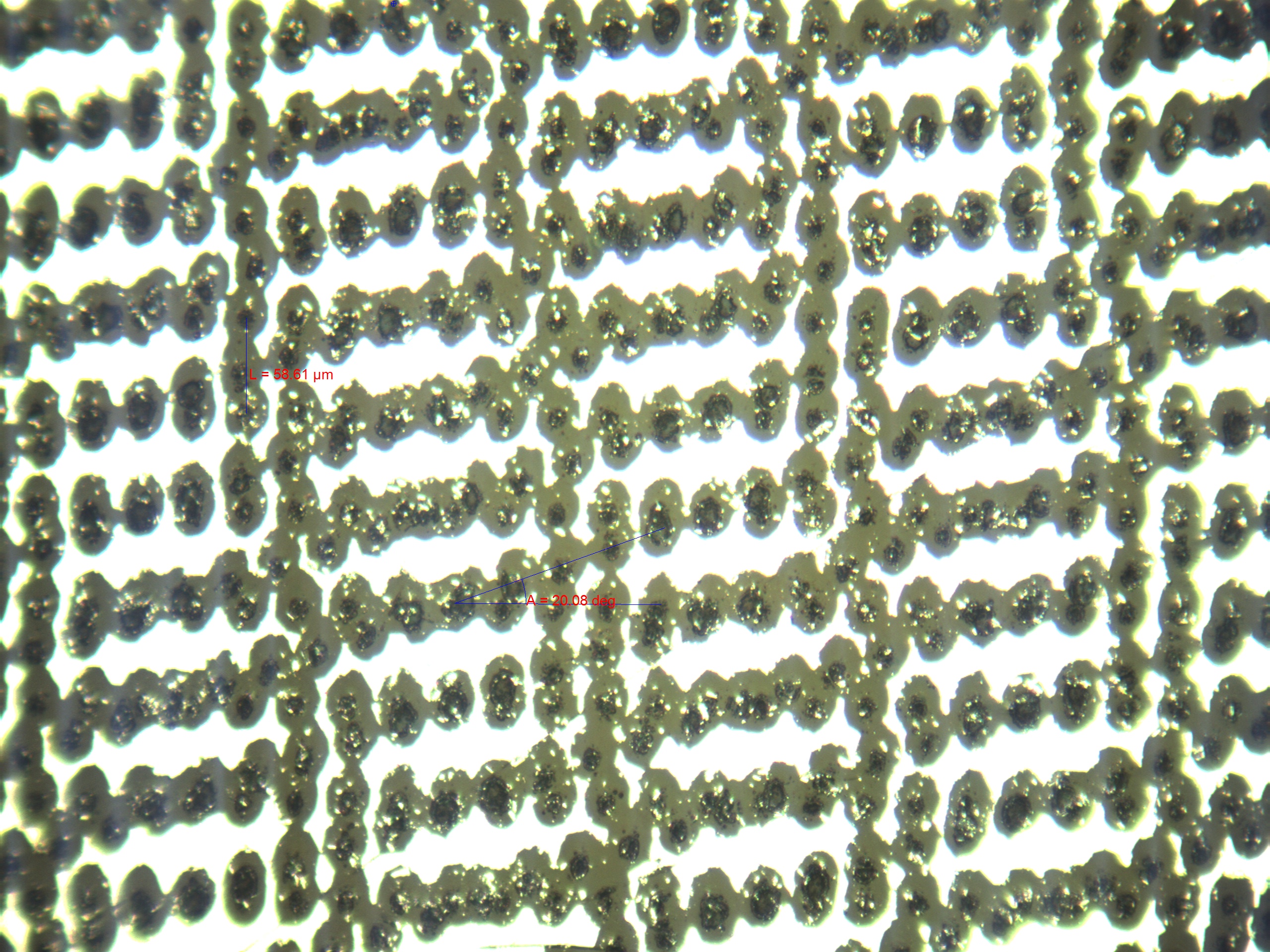 Fig 1: Crosshatch fill pattern, set to 20˚ offset, 60 micron line spacing, 10% power, 30kHz, and 4000 mm/s cut speed. |
 Fig 2: Crosshatch fill pattern, set to 70˚ offset, 60 micron line spacing, 10% power, 30kHz, and 4000 mm/s cut speed. |
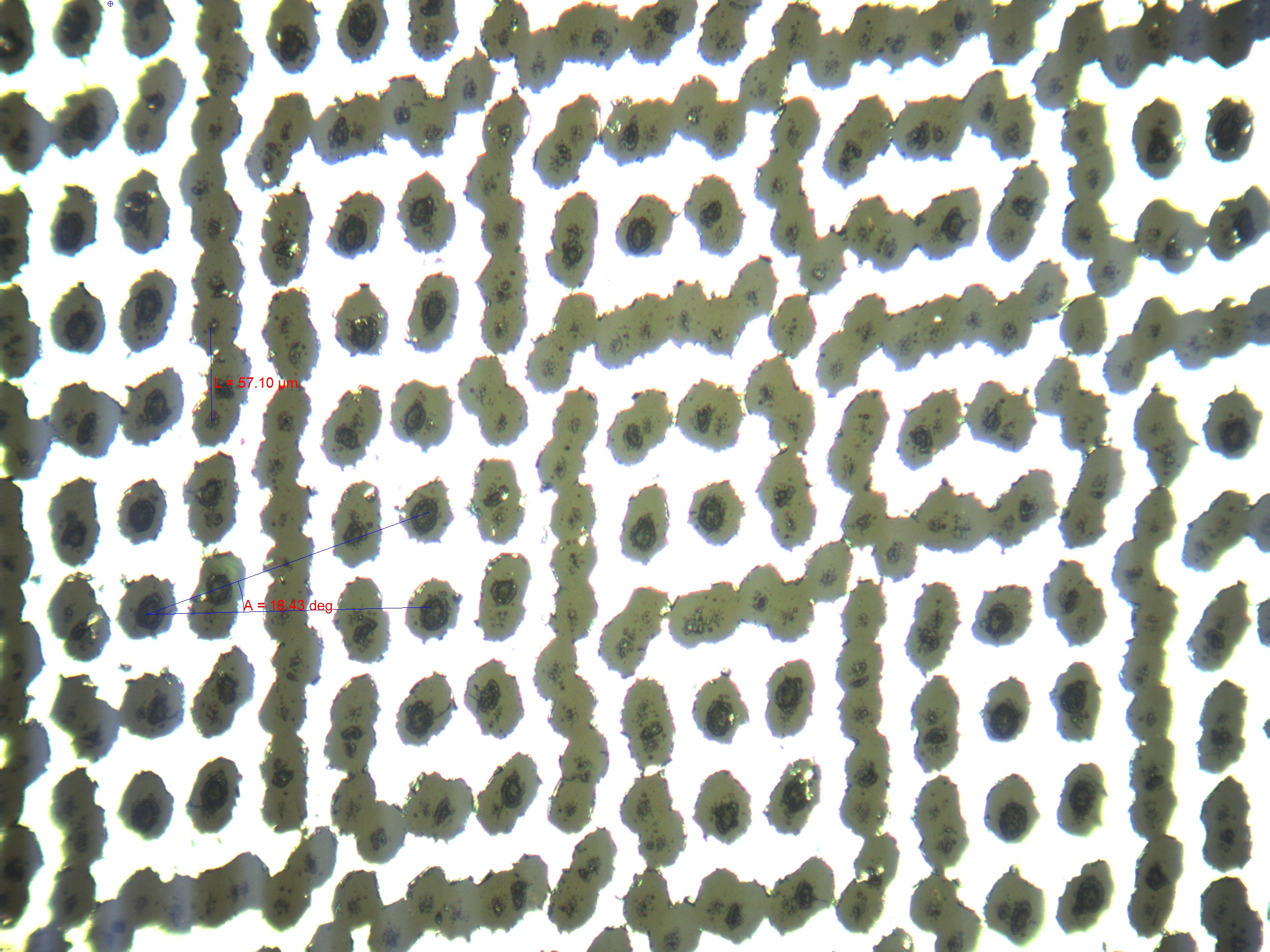 Fig 3: Crosshatch fill pattern, set to 20˚ offset, 60 micron line spacing, 10% power, 30kHz, and 5500 mm/s cut speed. |
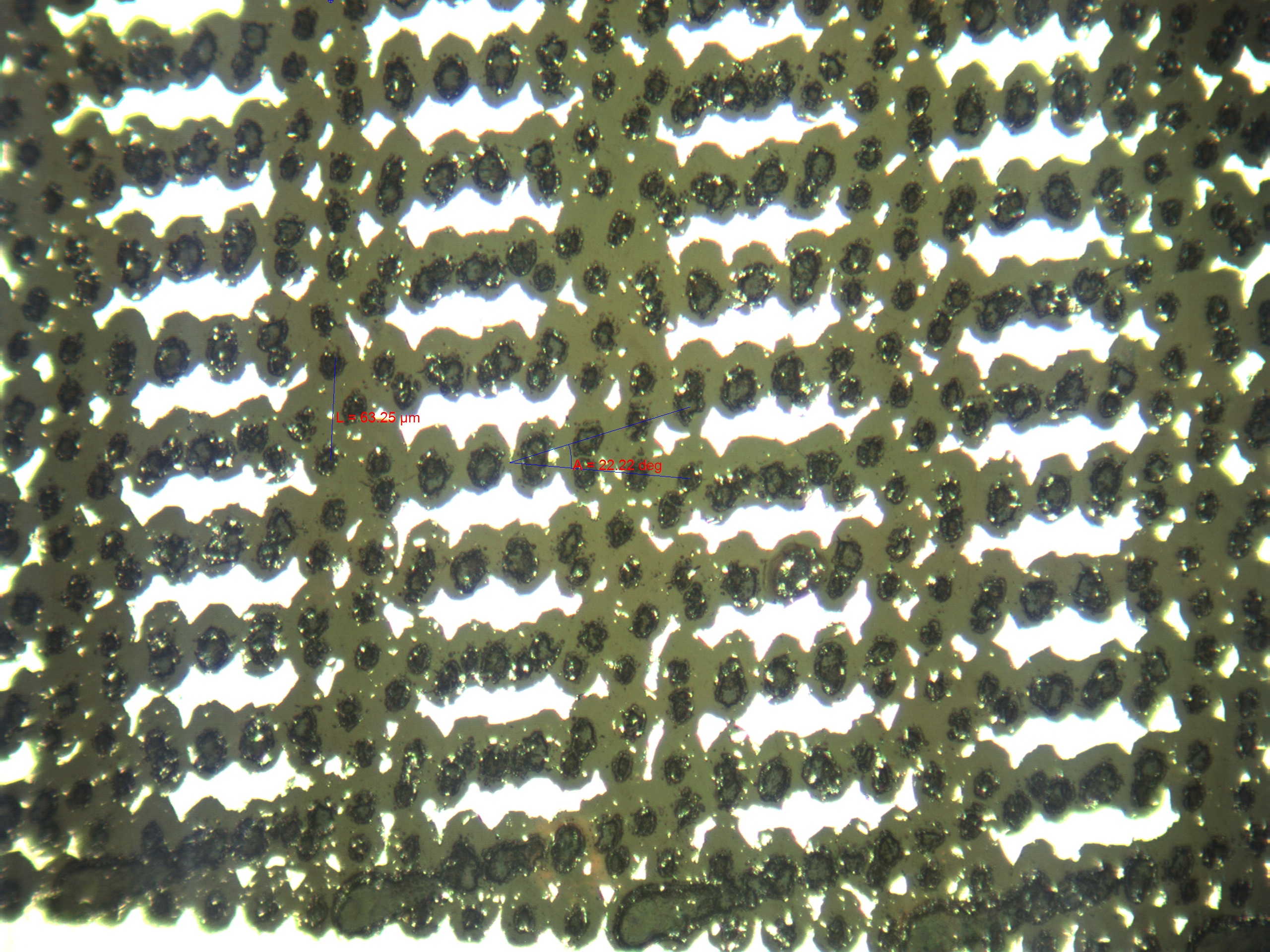 Fig 4: Crosshatch fill pattern, set to 20˚ offset, 60 micron line spacing, 20% power, 30kHz, and 4000 mm/s cut speed. |
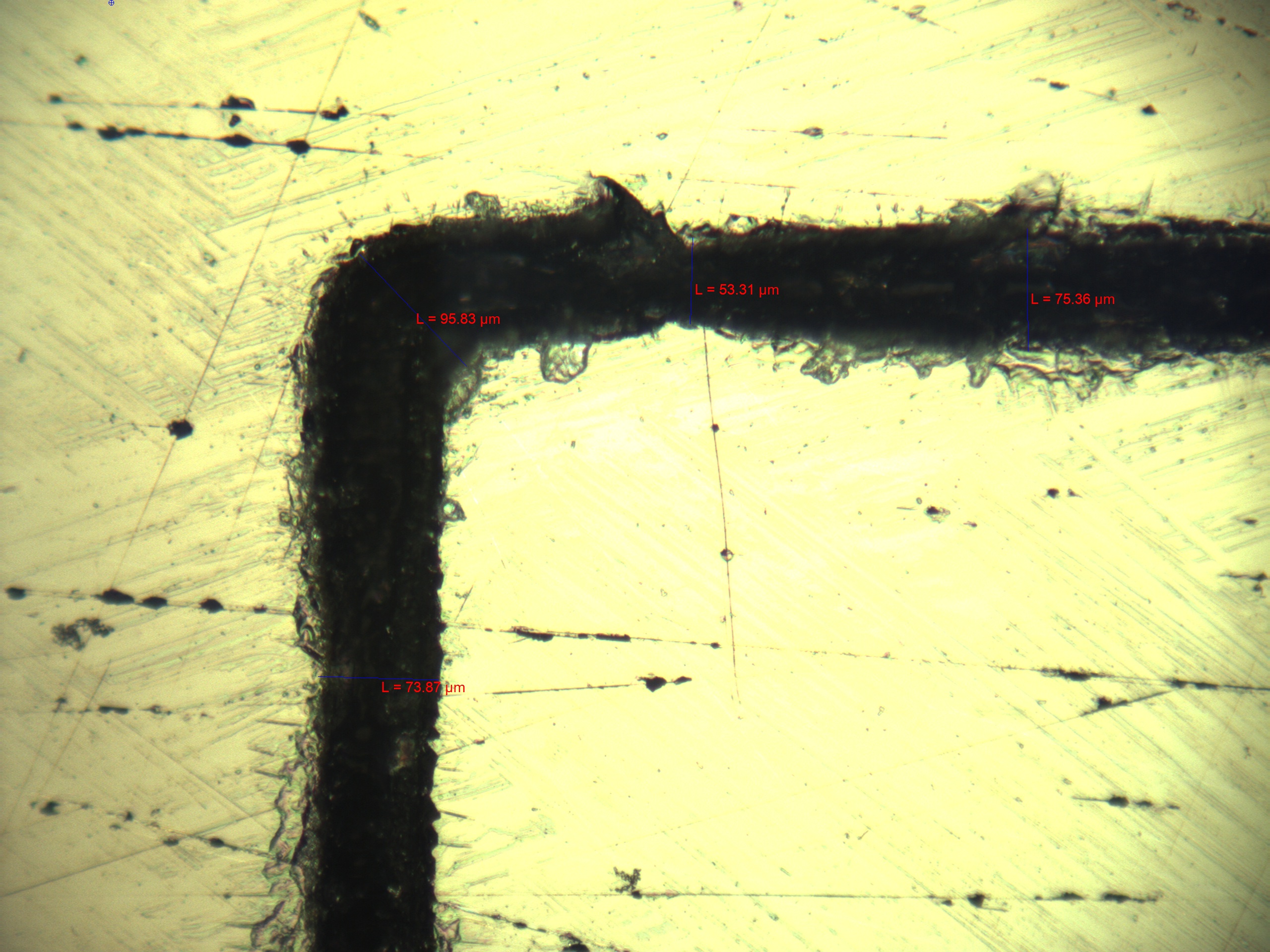 Fig 5: Single cut, 20% power, 30kHz, and 500 mm/s cut speed. |
 Fig 6: Single cut, 20% power, 120kHz, and 500 mm/s cut speed. |
I also wanted to see how effective the metallized Mylar would be as a flex circuit, relative to copper coated Kapton. I cut a thin strip of the Mylar, put it in series with a resistor, and applied a voltage to see how much current it could handle. A rough estimation indicates at least 100mA, but I want to do a more thorough test later, double checking the voltage drop across the Mylar with a voltmeter. To end the day, I tried etching the copper off of the Kapton, which now has me varying the number of passes on the laser, yet another parameter. On my first test, I succeeded in obtaining a range of cut depths from scratching the surface to complete through cuts, yet all of them remained conductive due to copper debris bridging the gap. The next step will be to try multiple lines offset by a small amount to obtain a wider gap.
Tuesday July 8
I got to play around a bit more with etching the metallized mylar, only to find that a single line is a perfectly good insulator. However, I did get some interesting results by varying the crosshatch angle. Several of the test patches were more than just conductors or not, they actually had an associated resistance. Moreover, this resistance does not vary linearly with the crosshatch angle. Given the delicate nature of some of the geometries and the precision of the laser, I'm not sure how repeatable these resistances are. Tomorrow I'll see if I can reproduce these resistances, and maybe explore the possibility of printing a resistor directly onto the mylar. Who knows, maybe I could do a capacitor too!
In other news, Germany beat Brazil 7-1 in the World Cup semifinals, setting all sorts of records. It was a bit sad to see Brazil play so poorly, but as a Germany fan it was a fun game to watch.
Monday July 7
I started making some test patterns on the laser, particularly checking out filling patterns available on the laser software. So besides laser power, frequency, speed, and number of passes, you can also pick between parallel, crosshatch, and bidirectional fill, varying line spacing for all three and crosshatch angle. There is currently an issue with the mylar not lying flat, which causes inconsistent cuts. I have also been able to get on the microscope, which has been very enlightening. I don't have any specific results so far, but at first glance it seems that there is a lot of flexibility with parameters if the only goal is to have the surface conduct or not.
Today I also attended my first PhD defense by Ann Majewicz from the CHARM lab. It was a cool presentation on needle steering, and really interesting to see the process of designing, executing, and communicating such a large research project.
Thursday July 3
Coming back to work after the wedding, I started by checking out more quad rotor options, and generally getting more well versed in terminology and available options. I also read a couple papers, one on the micro manufacturing techniques used to make the gecko adhesive, and one on a hybrid electrostatic/gecko adhesive that combines the advantages of each adhesion method. I finally got started on the laser, by learning how to run the machine, and also making some test cuts with Arul's test pattern (varying frequency and cut speed) on metal-coated Mylar. At first glance, it looks like we successfully etched off the metal while still leaving the Mylar, which was the goal to begin with. The next steps are to be able to interpret the cuts on the microscope (and finding some way to evaluate cut depth), and to play around with laser parameters to populate some documentation on cut properties.
Friday June 27
Today was lab retreat at Sam McDonald park, which was a wonderful experience of cycling, hiking, soccer, Swedish lawn games, delicious food, and good company. We also outlined our goals for the summer, which was useful both to condense my own goals, but to see everyone else's as well. This weekend I'll be out of town at my cousin's wedding, and I'll be missing a few days next week too.
Thursday June 26
Met with Matt this afternoon to discuss specific projects and goals for the summer. For me, that includes characterizing and documenting the new laser, and helping out with making the perching quad rotor video (first step: get a hackable quad rotor). Here is the link to the quadroter page.
Wednesday June 25
Finished my little Arduino LED memory game. Then Bobby and I helped characterize an accelerometer and a continuous servo motor for Matt. We also characterized two micro DC motors using the techniques we learned in ME112, which was cool. We would be operating at ~0.1 Nm or 14 oz-in of torque, which is very near peak efficiency according to our analysis.

Tuesday June 24
More Arduino today. I'm trying to get a simple memory game set up with three LEDs and three push buttons. It's not finished yet, but hopefully I can get it running tomorrow. In the afternoon, we analyzed how much torque is necessary to wind our tape-measure RollaWing. Using a 3/4" dowel, we found that we need ~0.1 Nm, so the solution will most likely be the smallest DC motor we can find running for a long time to wind the wing. Tomorrow we hope to characterize a few motors lying around the lab.
Monday June 23
This morning was the SURI kickoff meeting, and with it came the other undergrads to the BDML. So far I've only met Audrey, who's started working with Hannah on the underwater grasper. Today was also the first day of a weeklong Arduino workshop, which should be useful in the coming months. Bobby and I worked through just about all of the scheduled material, so we'll have the rest of the week to just tinker. Right now we're working with an accelerometer, and importing the data to MATLAB for analysis. Hopefully we can get something really cool by the end of the week!
This plot shows the raw accelerometer data in three dimensions from a test where we jerked the sensor once in one direction.

These plots are the result of integrating the acceleration data once (velocity) and twice (position). You can see how the accelerometer was not sensitive/accurate enough to give very useful velocity/position data, since the velocity did not return to zero, and the position drifted linearly when it should have been stationary


Friday June 20:
We made some more progress on our glider with a refined design of the RollaWing housing and mechanism. The new prototype was more robust and addressed the issue of guiding the retraction/extension of the wing, although there are still issues with wing positioning and extendability. Our next idea is to buy a tape measure that we can dissect, perhaps flipping the internal spring to demonstrate the functionality of our retraction/extension mechanism.
Thursday June 19:
Day two. Bobby and I met with Morgan again to go over more of the specific design criteria for the wings, like shape, weight, aspect ratio, loading, maximum deflection, extensibility, and deployment. We reaffirmed our tape measure based design, and did some analysis on a wing that was a single sheet of spring steel, but determined it would be too heavy. The rest of the day was spent refining the glider prototype, first by increasing the aspect ratio of the wings, making the elevator more robust, and creating an onboard mechanism to retract/deploy the wings. Good progress so far, but there's a lot of work to be done tomorrow!

Wednesday June 18:
Today was my first day real day. I've been going to the weekly meetings during spring quarter, so I have a bit of an idea about what projects are happening, but I learned a bit more about Morgan's jump glider and Hannah's underwater grasper. It looks like I'll have the chance to work on a bunch of different projects, and learn a lot from them. I'm particularly excited to learn more about mechatronics, sensors, and BDML's new laser.
Most of the day was spent on the jump glider, which Bobby has been working on for a bit already. The task is to develop an extensible wing, which will deploy at the apex of the jump. We played with his design a bit, and explored some new ones. Our favored design used two segments of a tape measure as the main wing support as well as the collapsing mechanism, with a plastic film between them for additional surface area. The quick and dirty glider we built to test the wing design worked quite well considering the time spent to build it.