category: SummerBlogs
Marcela's summer blog
Day 1, Week 1
June 19th, 2018
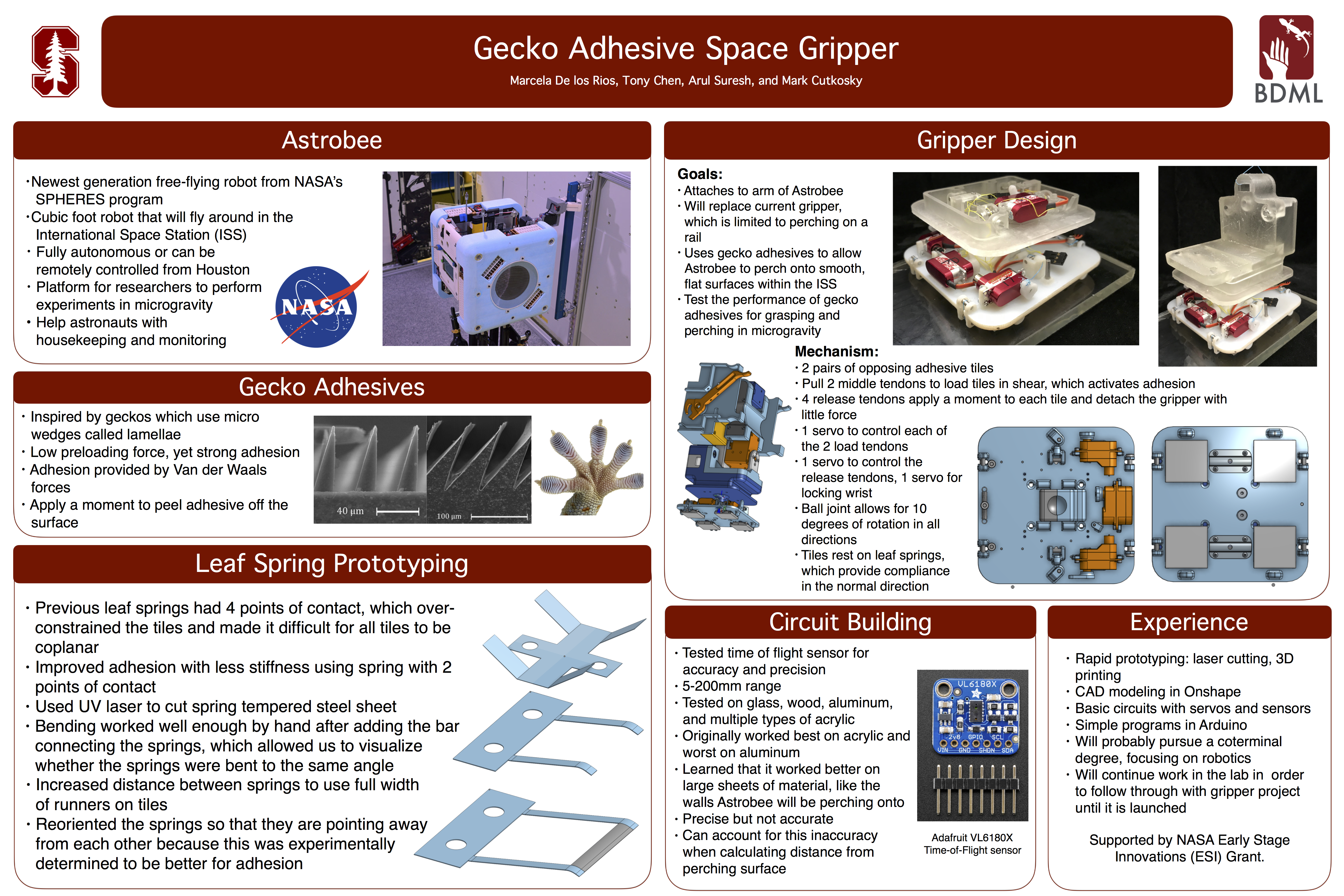
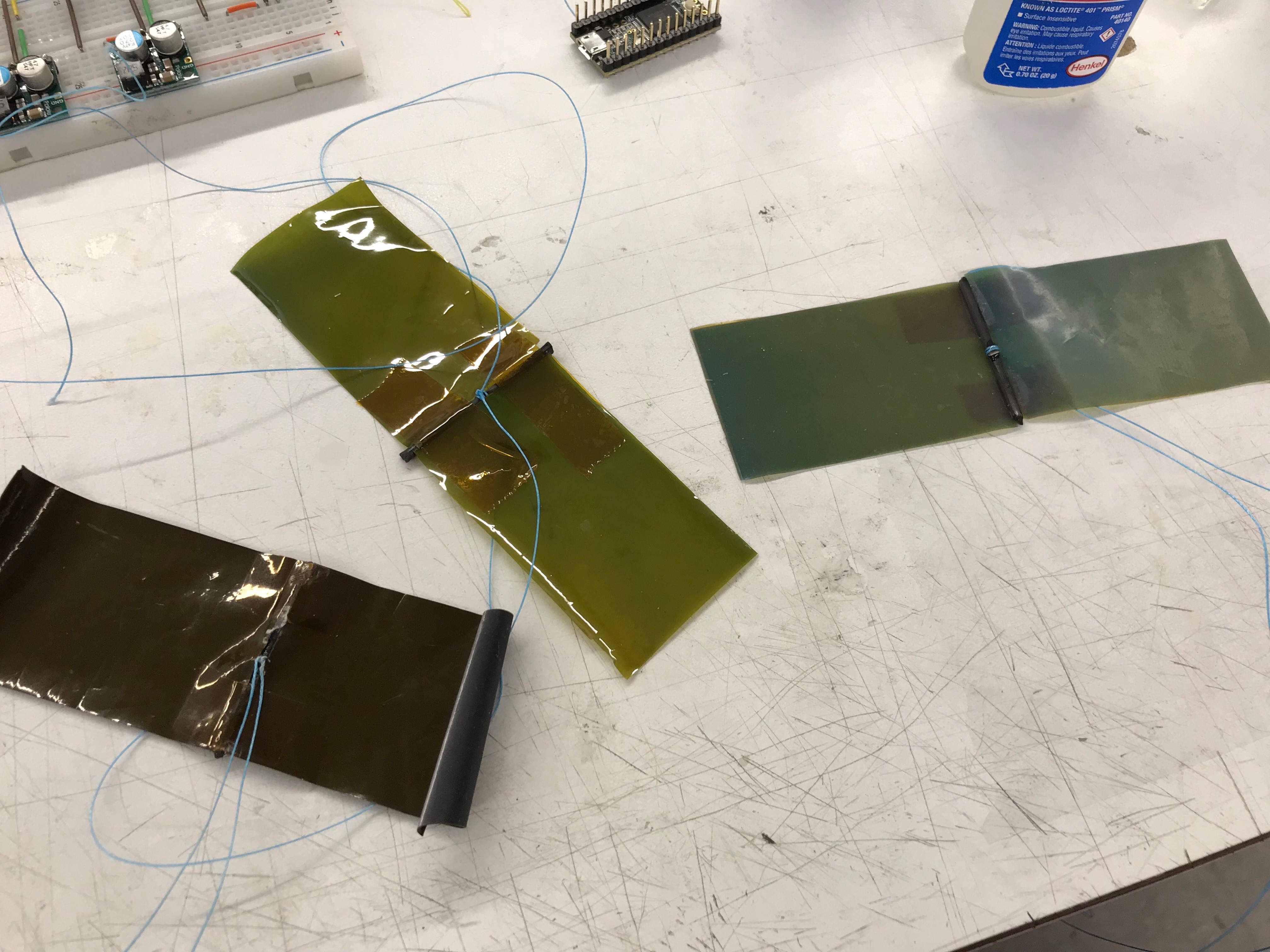
Alternative materials ranked from least flexible
to most flexible. Original material is laid
horizontally across the bottom above the final material
SuperSCAMP model with new legs
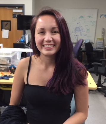
Marcela in BDML for summer 2018
Today I helped Stephanie with SuperSCAMP, mostly working on the robot's legs. The material we were currently using, a carbon-based material, was durable and somewhat pliable, but not flexible enough for the type of movement we were looking for. SuperSCAMP's legs should allow the robot to translate horizontally and vertically and curl when scaling a surface without a bowing motion. I spent most of the day looking for an alternate material that was slightly more bendable than the carbon, without sacrificing strength and sturdiness. I cut several strips of material out of different carbon sheets and tested for flexibility by analyzing how it bent and comparing how it functioned to a piece of the currently used material of the same size. Oftentimes, the material would seem strong enough when tested as a a full sheet, but would become significantly less sturdy and sometimes would even curl and twist when cut to the same length as the current material. On the other hand, other materials were too brittle and would easily fray when cut with scissors, demonstrating that it would most likely break if used for superSCAMP's legs. I was unable to find a material that worked when cut to the same width as the current material. Thus, I decided to use one of the materials that was too flexible and make it stronger by increasing the width of the strip. Once I created a strip with the desired thickness and flexibility, I attached it to the pulley system on SuperSCAMP's body.
Day 2
June 20th, 2018
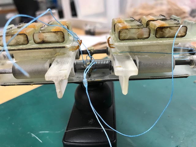
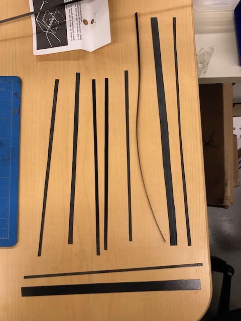
Active spine mechanism with a spring
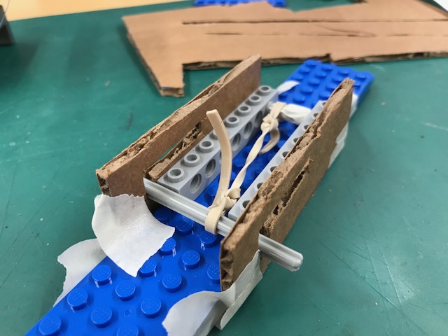
Prototyping with springs and legos
Today I listened in on a meeting between Stephanie and Will where they discussed possibilities for incorporating old spine ideas and current drones onto SuperSCAMP. We looked at several spines with different functions: one was meant for rough, flat surfaces and used an active mechanism, another was used for the same surfaces and used a passive mechanism, and the last spine was meant for rough, round surfaces like trees. The mechanism that was most applicable to SuperSCAMP was the active mechanism. When we returned to the lab, I analyzed the system that this spine used and prototyped with legos and rubber bands to try to create a similar system that could work for SuperSCAMP. The property of the old spine that I was trying to mimic was it's ability to compress, using a spring, and allow the spines to attach to a surface when perching, and then expand when taking off from a surface.
Day 3
June 21st, 2018
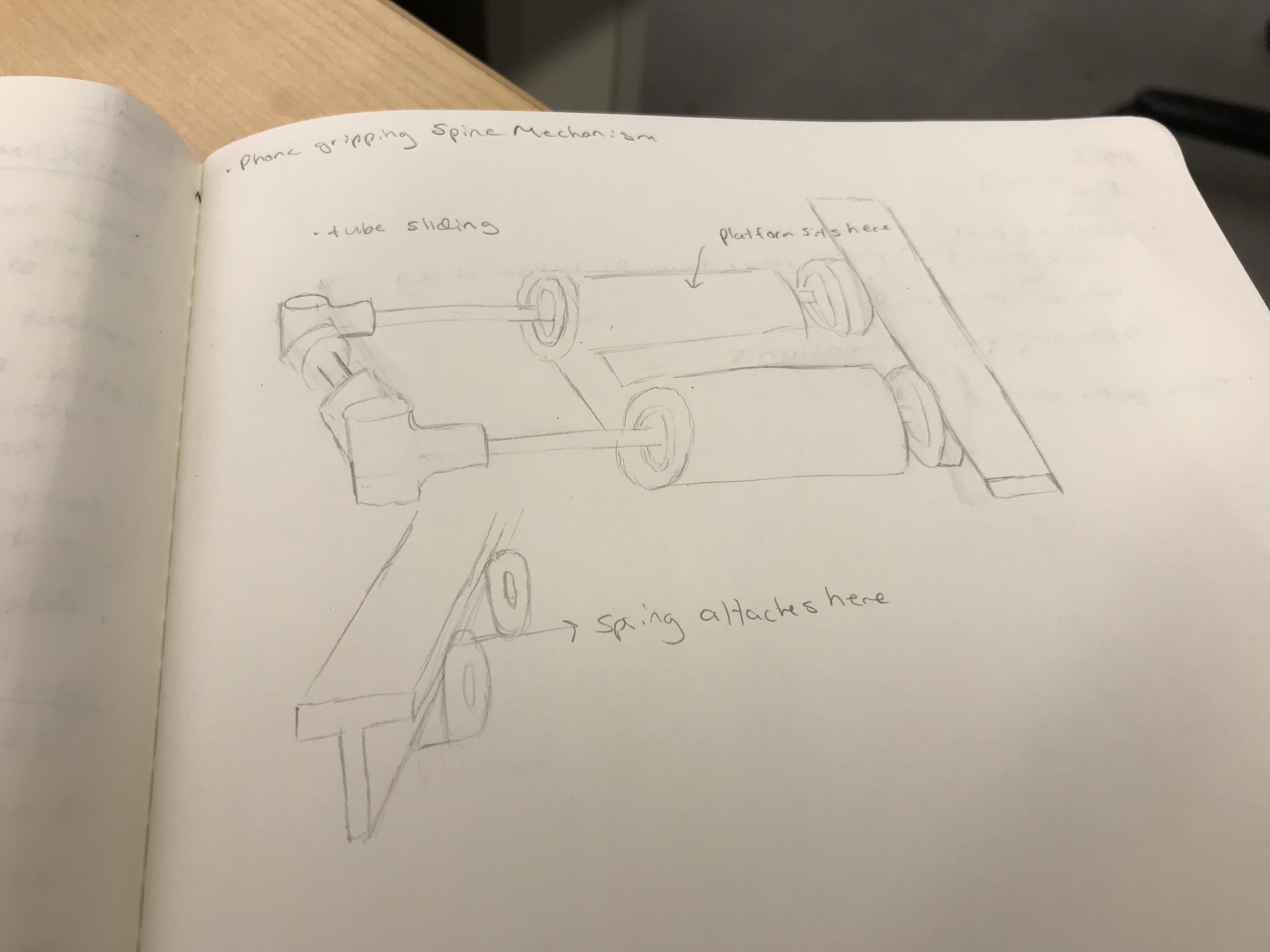
Sketch of previously used mechanism. This
one uses a tube sliding system
Because Stephanie is now rethinking the design and purpose of SuperSCAMP, I spent most of today researching past projects that were similar to SuperSCAMP and reading about how they overcame the challenges we're facing now. As mentioned earlier, we would like to use an active mechanism for SuperSCAMP because even though the motors make it heavier, slower, and less energy efficient, it makes the robot easier to control and results in a higher perching success rate. We also decided that superSCAMP will most likely use one actuator (servo) and that it will use 2 opposing groups of spines to allow the robot to adhere to the wall using shear forces. After reading several papers on past related projects, like SCAMP, I analyzed how they created their system and I noted whether they used mechanical stops, a cable and pulley, a tube sliding system, or another unique system. Additionally, I looked into how different projects designed their spines and how they mounted them to allow for compliance in the x and y direction.
Day 4 & 5
June 22nd and 25th, 2018
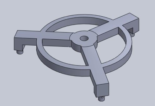
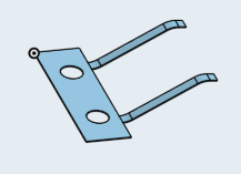
SolidWorks part file for base
Day 4 was mostly just a cleaning day, aside from lab meeting, but today I spent most of my time learning about Sam's project and past iterations of the project. I then began to create a SolidWorks part for a newer model of the project. The piece I'm creating will serve as a base that will attach to a handle for physicians to grip onto. It will also attach to three sliding glass tubes that will allow the machine to have a more optimal, controllable motion. The base I created in SolidWorks includes a hole in the top, designed so that many different types of handles can fit in the space. This part attaches to the glass tubing on each of the three legs using a universal joint, which allows for relatively frictionless motion in the x and y direction and slightly more friction when rotating. Also, I included circular trusses connecting each of the legs for support.
Day 6, Week 2
June 26th, 2018
Practice gecko skin pieces
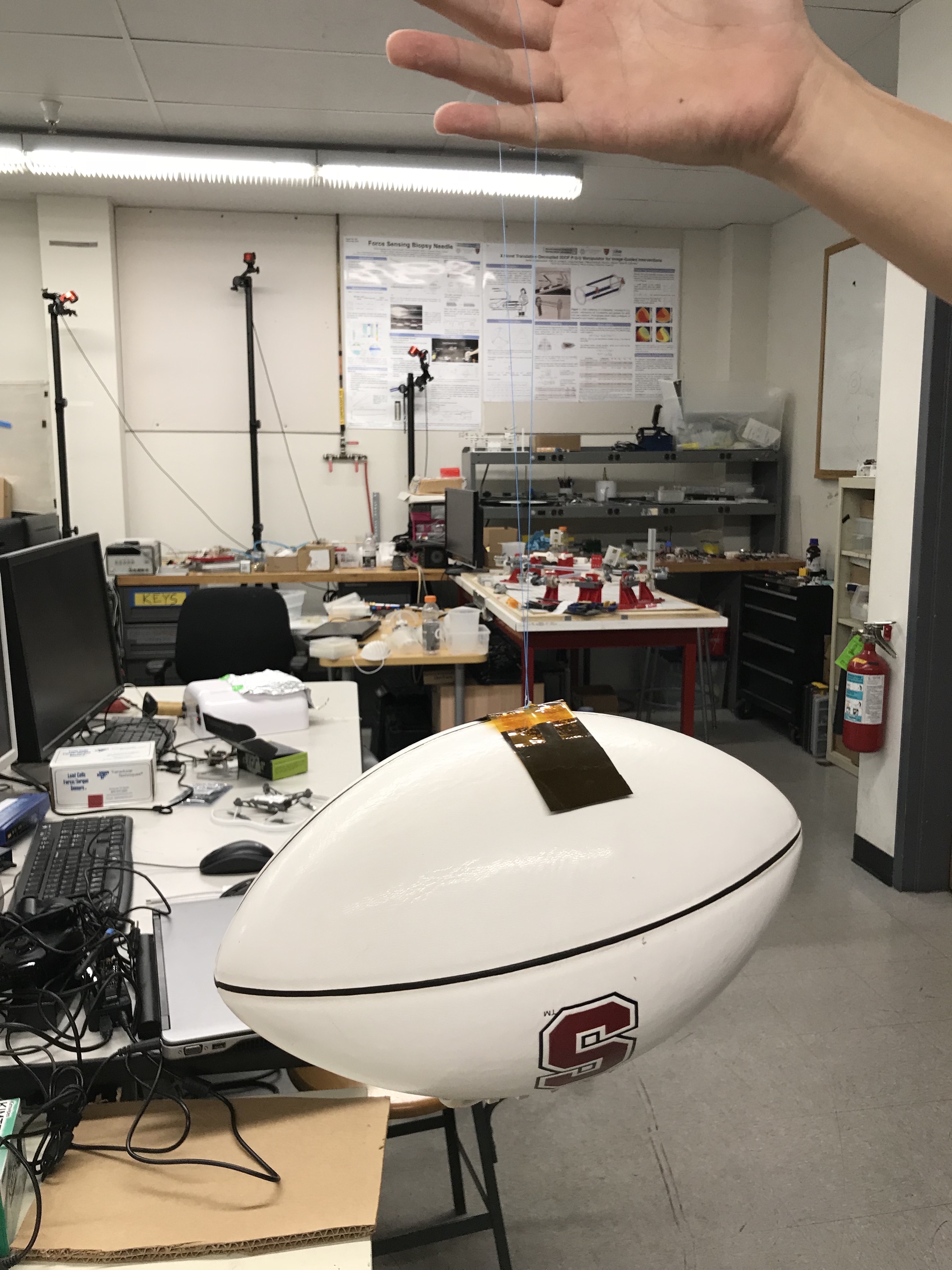
Football demonstration with gecko adhesive
I spent most of this morning finishing up the SolidWorks part for Sam's project. I am working on adding the correct dimensions to the base so that it fits properly with the handle and the universal joints. Later, I helped Tony create more gecko skin adhesives. Earlier this week, I watched him use the reusable mold to create a layer of gecko skin on a fiberglass backing. Although this attempt did not work out, I was able to see the process of using a mold to create the gecko skin. After Tony made a successful mold with a different backing, I cut and pieced together several different gecko adhesive strips that will be used for demonstrations like the football demonstration show in the picture. In order to get the hang of how to cut and fix the pieces together, I practiced on pieces whose microwedges had already begun to deteriorate. I then made a successful new gecko adhesive strip and tried it out with the football demonstration. This new strip is a slight improvement from the older ones because I cut out the unused gecko adhesive in the middle of the strip and replaced it with a different material, saving some of this extra material to be used for different projects or demonstrations.
Day 7 & 8, Week 2
June 27th & 28th, 2018
Yesterday was lab retreat at the Portola Redwoods State Park. It was really nice to bond with the other members of the lab, and it was helpful for me to hear about which careers that alumni from the lab go into and what their experience is like there. Today I finished the SolidWorks part for Sam's project by adding some fillets to the part's edges and ensuring that the dimensions were correct. Later, Tony got me up to speed with what they're currently working on for the NASA space gripper, the current problems they're encountering, and what their plan is for possibly resolving these problems. I will most likely be helping to finalize the gripper design, which will involve some CAD and 3D printing, and I will be able do a little bit of programming and playing around with sensors. I also got an Arduino micro controller today and Tony then began to teach some of the basics to me, explaining the difference between digital and analog, event driven tasks, timers, and breadboards. I'm really glad I have some programming experience because even though Arduino is in C, the concepts all seem very familiar from the class I took this year and I think I will be able to understand everything much quicker now. Overall, I'm really excited to be practicing more mechanical skills and rapid prototyping as well as some programming and circuits, which I'm not quite as familiar with but would really like to learn.
Day 9-11, Week 3
June 29th-July 3rd, 2018
For the past couple days, I have mostly been assisting Tony in creating new gecko adhesives and learning more about the process of creating the gecko adhesive tiles for the NASA space gripper. The most difficult and meticulous steps are intended to make sure that each tile is completely flat, otherwise the tile will not adhere as well. Additionally, we had to be very cautious when making the strips of gecko skin, in order to prevent bubbles from appearing in the gecko adhesive or from ruining the mold by accidentally tearing off the micro wedges. Today we made 3 successful pieces of gecko skin, two with the flexible backing and another with the fiberglass backing.
I also did a lot of research today on possible designs for a 2-leaf spring that will attach the tile to the rig because the previous leaf spring design had 4 points of contact and was over-constraining the tiles. First, I studied what the most common uses for leaf springs were, including automobiles and battery contacts. Typically, they exist in a vehicle's suspensions systems and they provide support for the vehicle while also absorbing any uneven surfaces over which the car travels. For cars, they are often made out of one, or multiple, thick pieces of steel. However, for smaller leaf springs like battery contacts, which are more similar to what we will be using, they can be made out of spring tempered steel, or even paper clips depending on its intended usage. In the end, I decided to go for a relatively simple design in which the bolts will be perpendicular to the tendon and in line with each leaf on either side of it. I will make several copies of this leaf spring with varying thicknesses for the leafs. Tomorrow and Friday I plan to work on the CAD files on Onshape for the leaf spring so that we can laser cut them as soon as possible. I will also CAD a test rig that will be designed so it is easy to disassemble and adjust the tension in the springs. This will be helpful in collecting some data and seeing how successful the springs are.
Day 14, Week 3
July 6th, 2018
Today I finished laser cutting the test rig and leaf spring designs that I had been working on. Tomorrow I will work on assembling the test rig with the leaf springs, tiles, gecko adhesives, and tendons. I will run some tests to see how well the new design for the 2 leaf spring works with each of the different sized leafs. I slightly modified my previous design, keeping the two bolts perpendicular to the tendon and the 2 leafs on either side of the tendon.
Day 15, Week 4
July 9th, 2018
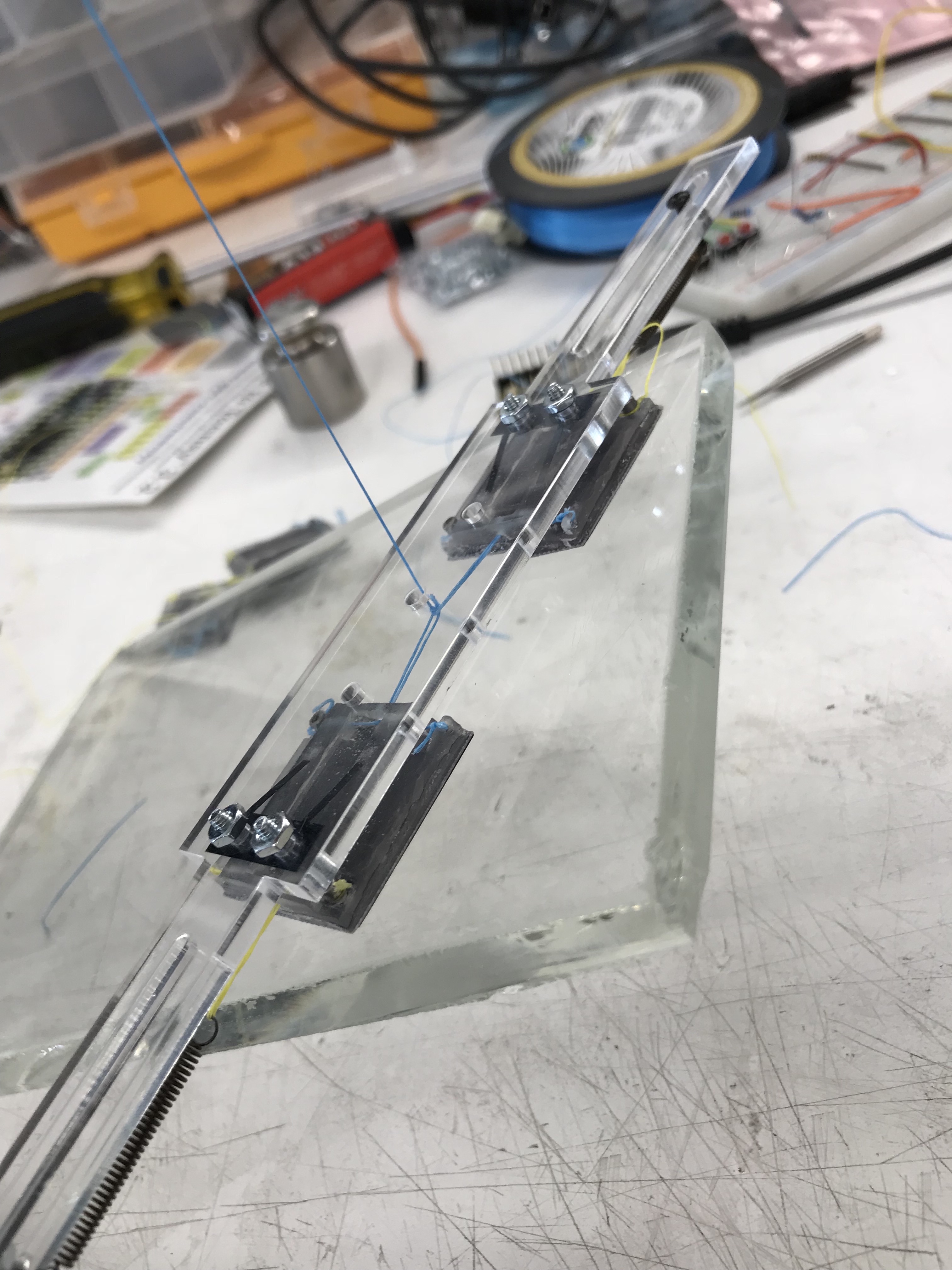
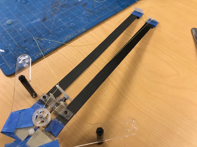
Succesful test rig with the 2-leaf
spring lifting a piece of glass
I made a successful test rig today using the leaf spring with only two points of contact. This rig only had one pair of tiles, but we plan to make more tiles and springs tomorrow so that we can assemble a piece with 2 pairs of tiles and see how well it works. The 1 pair rig weighs 21g and it has a ~13g preload. I used the leaf spring with the smallest leaf width, which was 0.05", so that the system would be lighter and the k value would be less, leading to a smaller activation force.
Day 19, Week 4
July 13th, 2018
4 tile rig prototype
Sheet metal model of leaf spring with 2 bends
This week, I have been working on creating and improving a 4 tile test rig for the NASA gripper. On Tuesday, I assembled the 4 tile rig with the 2 point of contact leaf spring. It worked consistently, but only with a slightly larger preload than its own weight. Thus, I spent the rest of the week trying to improve the rig so that it adhere easily with only its weight as a preloading force. First, I added a second bend to the ends of the leaf spring so that the tile would rest more evenly across the surface of the spring. However, this did not improve the adhesion as much as I had hoped, so I began to explore other opportunities for improvement.
I noticed particular inconsistencies across the 4 tiles, preventing the 4 tiles from being on the same plane when pressed against the surface. Some of the holes that were drilled into the 3D printed test rig and the 3D printed tiles were too big, causing some of the tendons and bolts to slide. This significantly limited the rig's adhesive abilities. Therefore, on the next 3D printed parts, we will use smaller taps to drill the holes.
Additionally, because of the current process we are using to bend the leaf springs, they are not all bent consistently to the proper degree. Because of this, I spent most of today creating two bending rigs in Onshape that will consistently bend each spring and will be able to bend 2 springs at a time. I also edited our current CAD file for the leaf spring so that it is a sheet metal model and more realistically and accurately represents how the leaf spring should bend in order to achieve consistent adhesion. I measured the exact degree to which the spring should be bent and designed the bending rig based off this measurement. Now that I have CAD files for the bending rigs, I plan to 3D print them using the Object printer on Monday morning so that I can bend the leaf springs and assemble an improved rig next week.
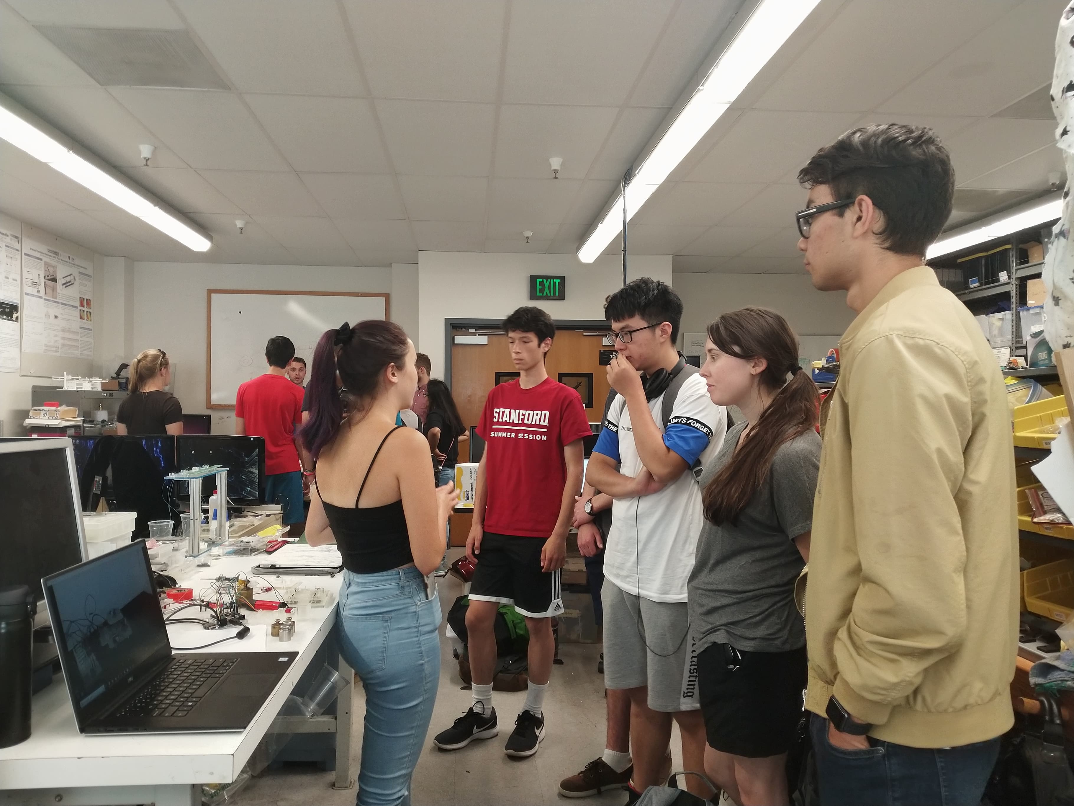
A week from Monday I will be presenting my research process so far at the SURI meeting. In order to practice for this, I presented the NASA space gripper project to the tour group of high school students today. It was helpful for me to get a chance to explain our project, give a demonstration, and answer questions, because this is very similar to what I will be doing at the meeting. I oftentimes also find it helpful to teach others about what I'm working on in order to fully understand it myself.
Giving a demonstration of the Astrobee gripper
Day 23, Week 5
July 19th, 2018
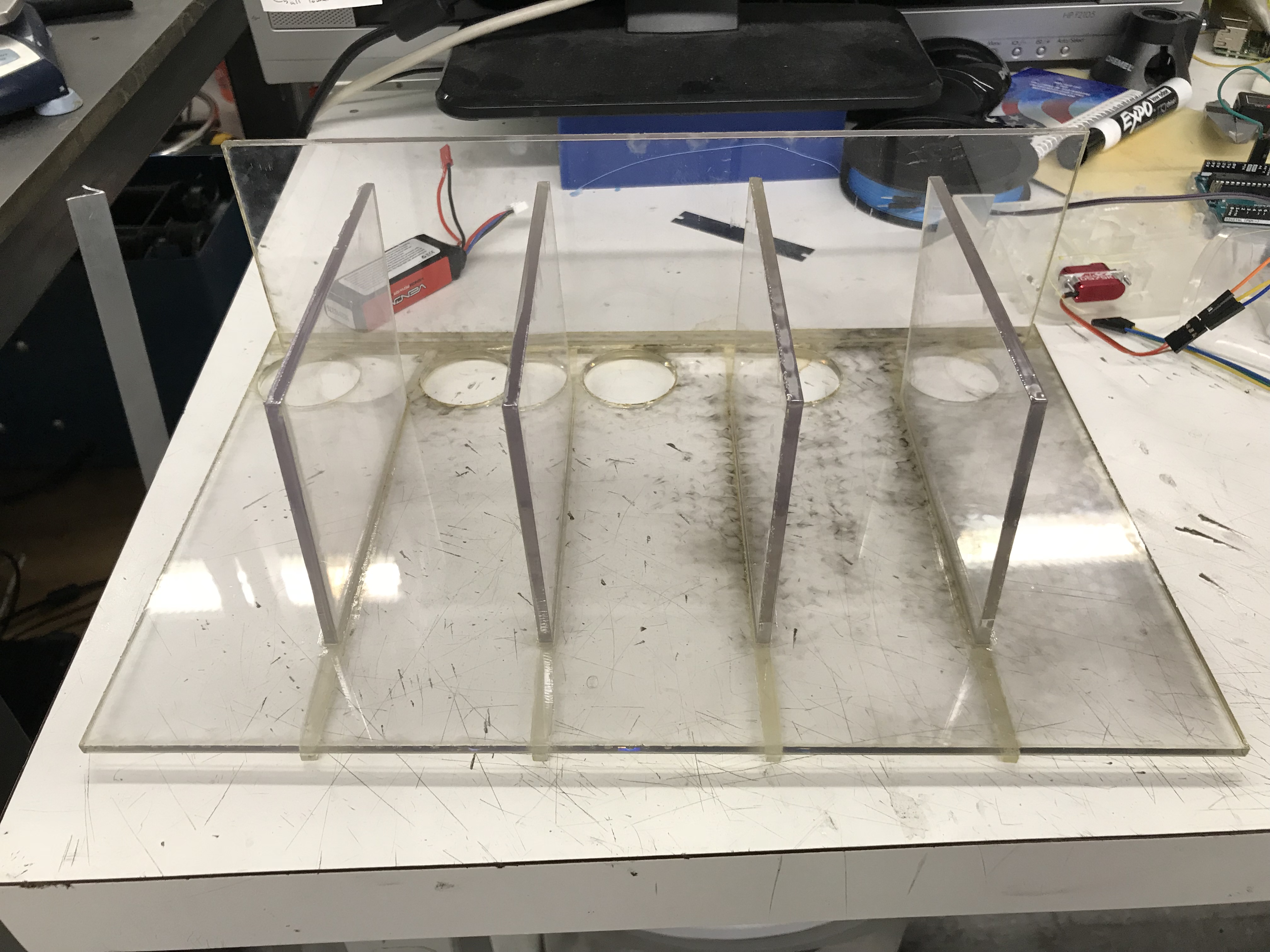
Resin cartridge shelves for new 3D printer
This week I have been working on assembling my improved 4 tile rig and helping Tony build shelves for the cartridges for the new 3D printer. At the beginning of the week, I was mostly taking measurements of the cabinets and cartridges in order to make the CAD files for the shelving. We wanted to design the shelving so that it was slightly elevated and had a hole where the resin might leak through in order to catch the dripping resin and clean it up easily. We are also using a special material that is similar to acrylic, but is very nonreactive and will not react to spilling resin. Much of our time laser cutting was spent adjusting the power settings so that it cut all the way through because there wasn't much information on how this material should be laser cut.

3D printed spring bending jigs
After Sam 3D printed the bending jig on the Object printer, I was able to test out how well the jig bent the leaf springs. I found that when the spring was properly clamped down to the jig, the spring bent almost exactly to the angle that is required for adhesion. I figured that if the angle was ever a little bit off, I could always simply use the digital calipers to measure the current distance and readjust them using the bending jig. The new design for the bending jig also helped to bend two springs to the exact same degree at the same time, which should allow the tiles to align better. The only issue I found with the bending jig was that the screws didn't screw into the jig very well because I didn't add threads to the hole and because the holes in the jig were slightly too large. Thus, I then adjusted the holes in the Onshape to be tapped holes that fit a 2-56 screw exactly. I now need to reprint the bending jigs, but I'm hoping this will allow the leaf springs to clamp down to the bending jig better and result in more consistent bends.
I also noticed that the hole for the screw in the leaf spring was a little too large and that sometimes the screws slid around on the leaf spring. I then adjusted the CAD file for the leaf spring and changed the size of the hole to fit a 2-56 screw based off a tap and drill chart. I will use the UV laser cutter to cut the adjusted springs later today.
Yesterday and today I had been focusing on assembling the improved 4 tile rig. On Wednesday, I strung together new tiles with smaller tapped holes so that the tendons wouldn't slide. However, I realized that because of the way I was tying the two blue tendons together, there was a small gap between them that threw off the measurements. I plan to fix this by threading the tendons through each other, and hopefully this will also improve adhesion.
Week 6
July 25th, 2018
This week, I used the most recent version of the bending jig to bend new springs. Adding threads to the holes on the bending jig helped a lot when clamping down the spring. The bending jig still does not bend the springs as accurately as I hoped, so I'm still looking for ways to improve it. In order to prevent the springs from breaking as easily, I will increase the bending radius. I also considered calculating the bending spring back in order to determine which angle the spring needed to be bent so that it would spring back to the desire angle. However, I decided that this is too difficult to determine using the equations for spring back because we don't have a consistent enough bending setup. Thus, I will continue to determine spring back experimentally.
We will most likely be getting rid of the holes on the base of the leaf springs because we will use super glue to attach them to the gripper. This means that we need a different way to clamp the spring to the bending jig. I plan to adjust the bending rig so that the screws are on the side of the jig and clamp down the spring without actually going through the spring. I also plan to change the design of the jig so that it is only meant to bend one spring at a time, since it doesn't work as well with two springs anyways.
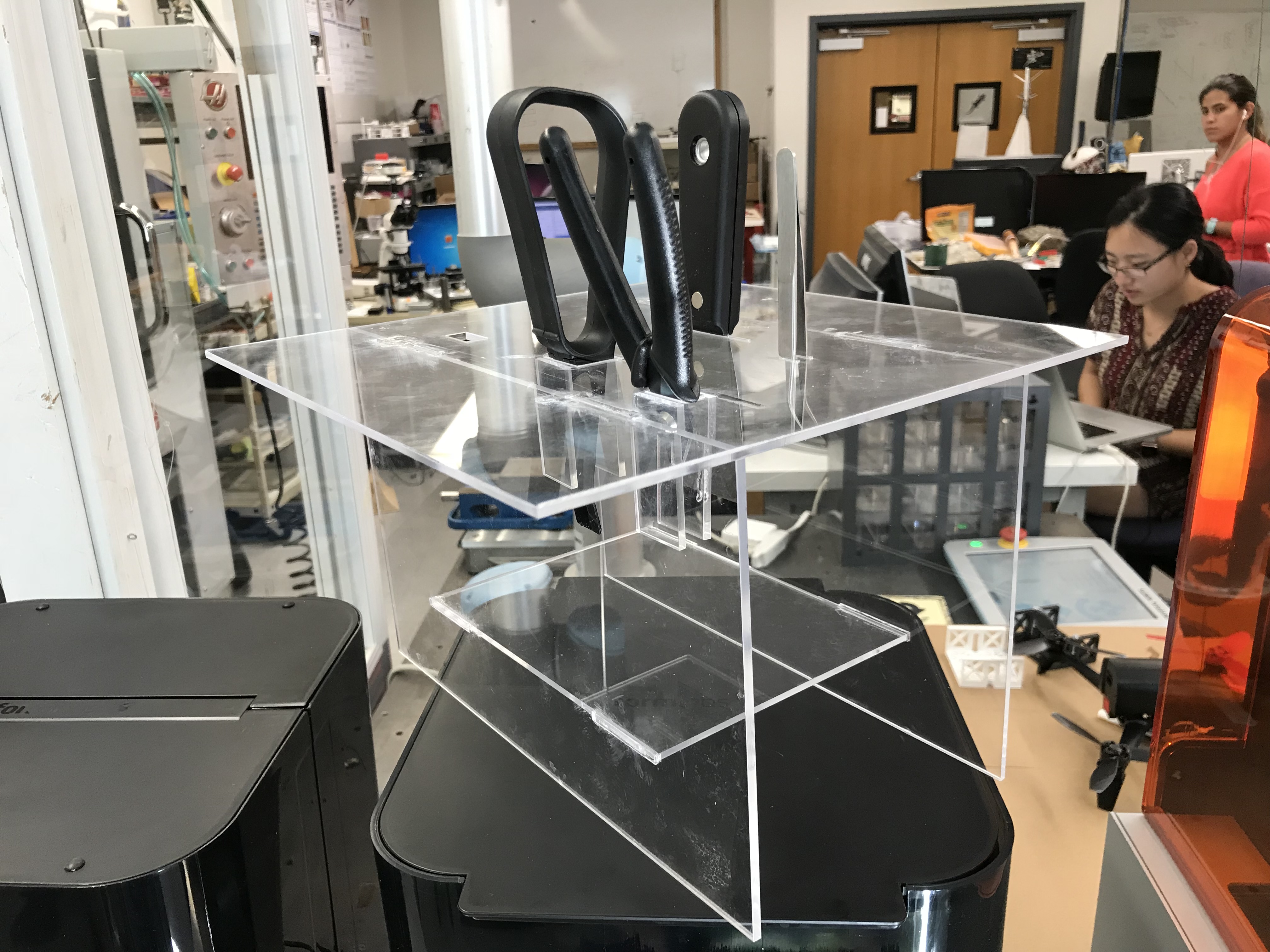
Shelves for 3D printer tools
I also spent a lot of time helping Tony build drawer shelving for the 3D printer tools. I designed a shelf with slots at the top that custom fit all of the tools, so that the tools can be placed into the slots with the handle sticking upwards and the edge of the tool with resin dripping from it facing towards the bottom of the shelf. At the bottom of the shelf is a platform where we will place a piece of aluminum foil to catch dripping resin for easy cleanup.
Week 7
July 30th, 2018
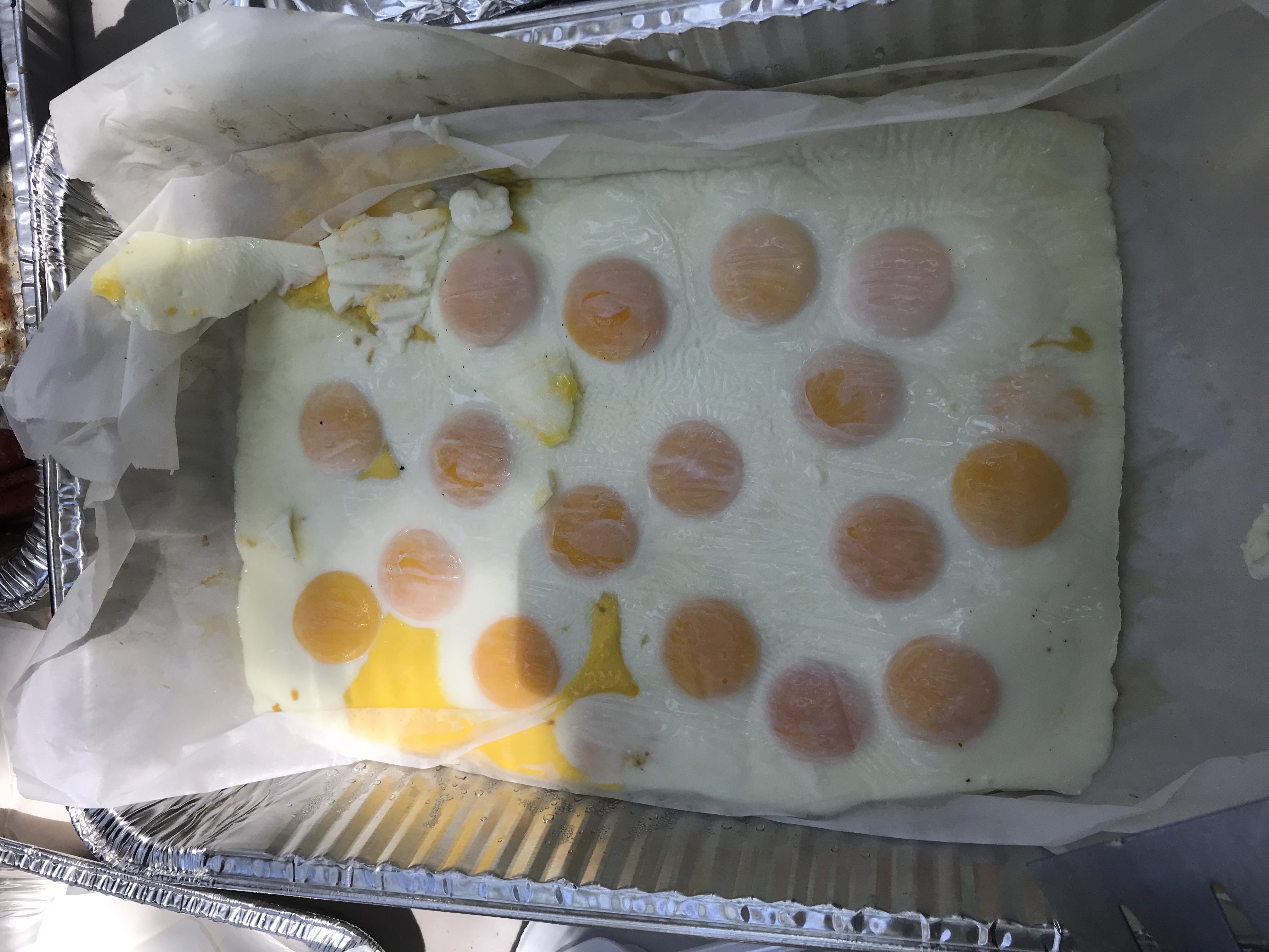
120 eggs!
Last Friday was our turn to cook food for MERL Barbecue. We made just enough food for everyone who attended and I was able to cook 120 eggs for everyone's burgers! I cracked as many eggs as I could fit onto buttered parchment paper inside a sheet pan, sprinkled them with salt and pepper, set the oven to about 425 degrees, and let them cook in the oven for about 5-8 minutes, depending on how runny we wanted the yolk to be. Because we cooked them on parchment paper, it was easy to transport the whole batch of eggs into an aluminum tray and stack the eggs on top of each other. Once we got to the barbecue, we simply cut the sheet of eggs into individual eggs and scooped them up with a spatula. (See the wiki page on "eggs" for more info)
When I assembled my 4 tile rig this week, we found several issues with the springs. First, the springs weren't quite wide enough to consistently stay on the rails of the tiles. It also didn't help that the preload was too low, so there was not enough tension between the tiles and the springs fell off the rail as the tiles slid around in the y direction. Additionally, the holes in the gripper were not drilled correctly, so we were not loading the tiles precisely in the middle. Lastly, the springs were not touching the middle of the tiles, which caused the inside of the tiles to be elevated above the outside of the tiles.
New spring with bar
Gripper with new springs and new configuration
We improved these issues by using a new gripper and gluing the springs at the correct location so that the tiles were loaded precisely in the middle and so that the leaf spring touched the middle of the tile. We also flipped the springs around so that the leafs are facing outwards inside of inwards. Then we adjusted the width of the springs to fit more properly onto the rails of the tiles and changed the configuration of the gripper so that the preload is higher. We then added a bar connecting the two leafs of the spring so that it is easier to assess whether the leafs are bent to the same degree. Tony and I also spent some time recalculating the exact angle that the spring should be bent based on these adjustments. We changed some of the other measurements on the spring as well so that the desired angle is relatively small and it will be easy to bend the springs to the proper angle without breaking them.
Week 7
August 2nd, 2018

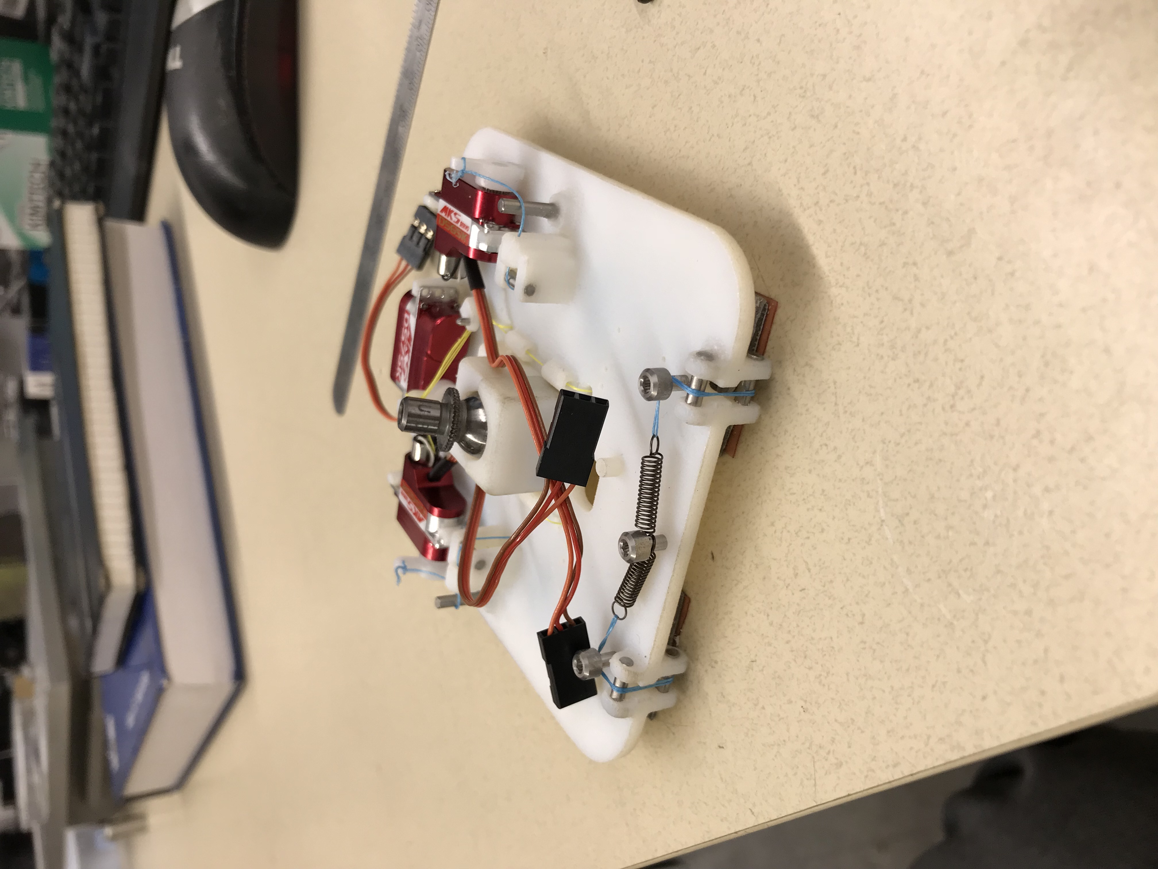
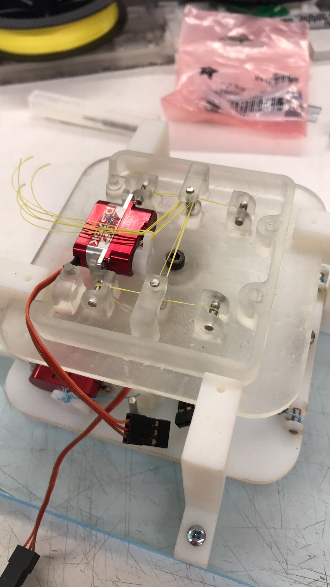
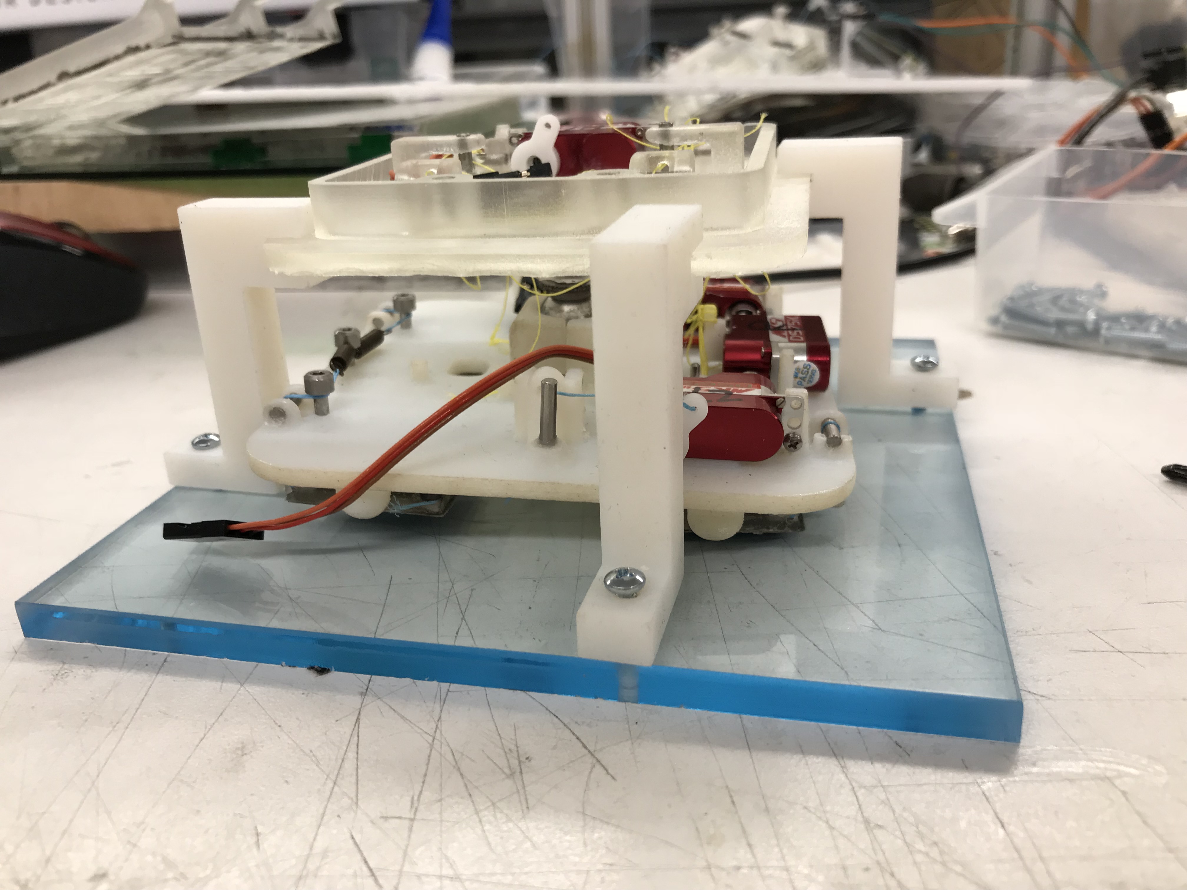
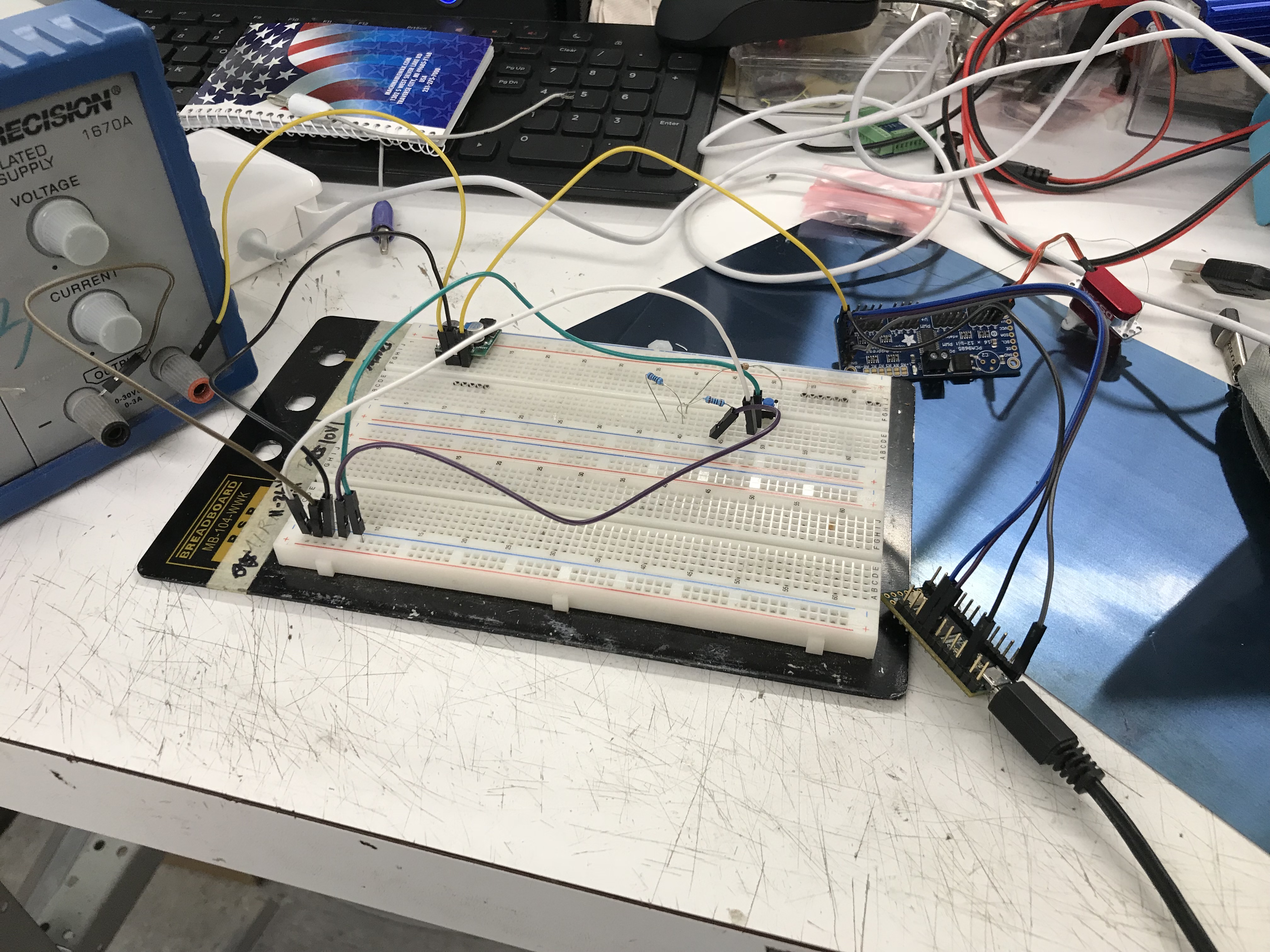
First circuit with sweeping servo horn
This week I successfully cast a gecko adhesive on the flexible caption backing. I'm trying to learn more about the manufacturing and casting process for adhesives so that I can make them next week when Tony is gone, if necessary. I may also have to practice casting them onto the fiberglass backing.
Today we decided on an official name for the Astrobee gripper. We decided to name it PALM (Passive Adhesive Landing Mechanism) because we wanted the acronym to accurately describe the function of the gripper (it functions like a hand/palm mechanism for the Astrobee robot).
I've also learned a lot more about circuits and began to write basic programs in Arduino. I reviewed certain electrical engineering concepts like circuit diagrams, resistors, and voltage regulators. Tony walked me through the circuit diagram for our current gripper, so that I know how to troubleshoot it if anything goes wrong next week. He also explained each line of code in our gripper's program so I will have a better understanding of how the Arduino programming concepts I reviewed apply to our gripper. I've found it very useful so far to have taken a basic programing class, even though it was in Java, and I've actually been pretty surprised at how similar it is to the programs I've written before. It's also helpful that I took a physics class in electricity and magnetism last quarter so I'm pretty familiar with basic circuit diagrams as well. It's been really interesting for me to see real world applications of circuit building and programming concepts that I learned the past couple quarters. For my first circuit, I started by assembling the wires and attaching them to the micro controller, breadboard, and a single servo. The first circuit I made was one that allowed the servo to sweep from a 0 degrees to 180 degrees with a smooth motion. I gradually improved the code so that you could use a button to control which angle you wanted the servo horn to be positioned at. On Friday I plan to learn more about sensors so that I will be able to perform the necessary tests on our gripper by myself next week.
Week 8
August 6th, 2018
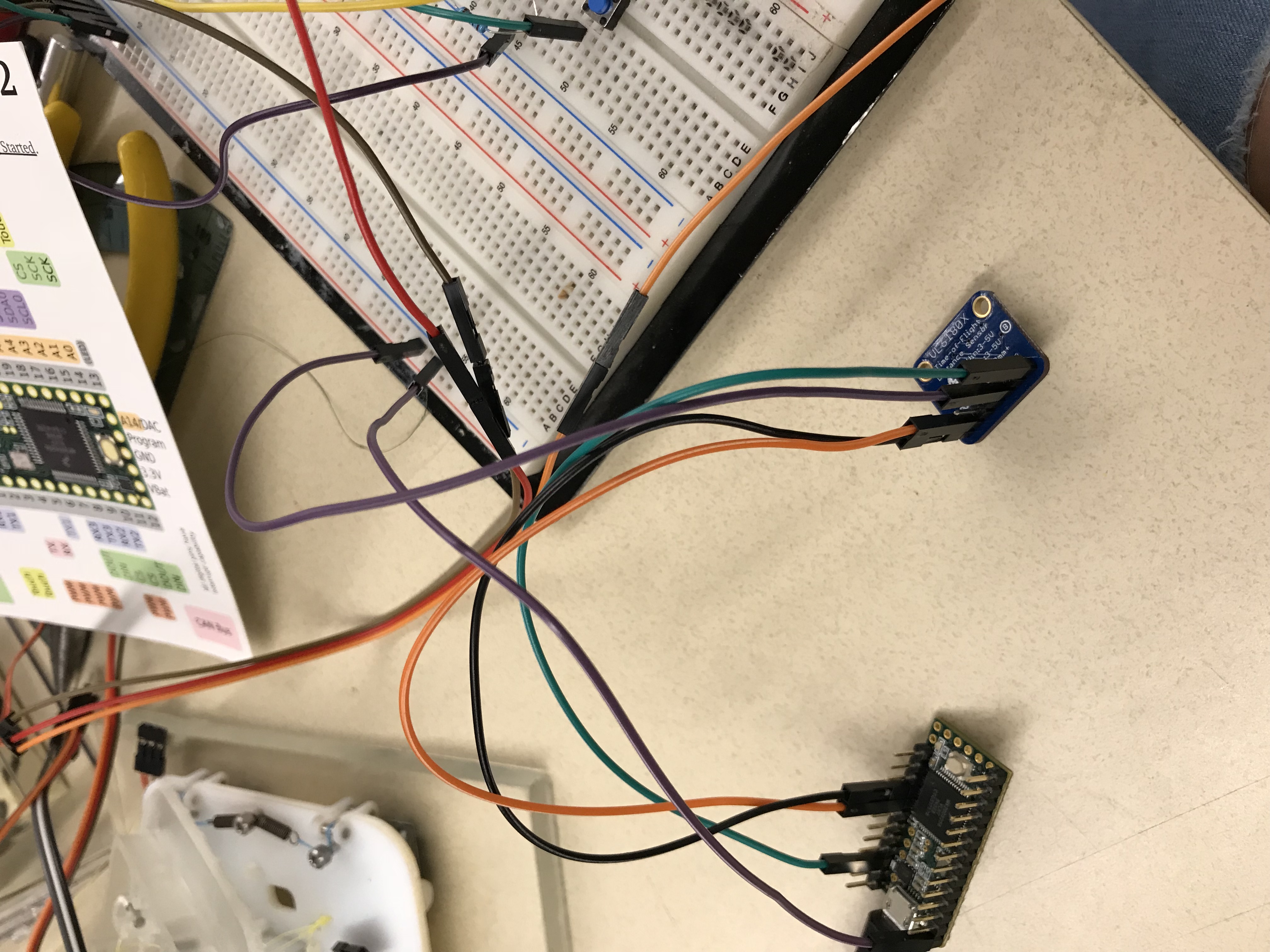
Circuit with time of flight sensor
Today I created a new part studio for the most recent spring design with a bar connecting the two springs. I converted it into sheet metal so that the model has the appropriate bends and is bent to the proper angle. This will allow me to easily add it to the gripper assembly in place of the old springs.
I also assembled a circuit with the Teensy microcontroller and Time of Flight sensor and began to test how well the sensor detects the distance from the gripper to various surfaces, like glass or the table. When attaching the sensor, I originally thought I would have to use a voltage regulator to properly adjust the voltage to what the sensor can accept. However, the Adafruit documentation on this sensor mentioned that the power pin can accept about 3-5V and can safely convert it down using a built in regulator. Thus, I then attached the Vin pin to the 3.3V pin on the Teensy micro controller and uploaded the demo into Arduino.
When I first taped the sensor to the gripper, the sensor didn't lie perfectly flat and it would give me a reading that was about 3mm off from what it should've been. I thought that this inaccuracy might be due to the tape slowly peeling off or because the position of the sensor on the gripper made it difficult to use calipers to measure the actual distance. However, Tony confirmed that when he tested the sensor earlier, it usually gave a reading within about 2mm of the correct distance, so this slight inaccuracy may be due to the sensor's limited capabilities.
Tomorrow, I plan to test the sensor without attaching it to the gripper, in order to get the most accurate measurement. I will probably also build some kind of small housing to further test the accuracy of the sensor and measure the exact distance from the sensor to another flat surface. We are interesting in seeing how different the reading might be for surfaces where the light diffracts through the material.
Week 8
August 8th, 2018
Yesterday I spent some time creating a jig for tying the load tendon strings. It is designed to clamp the tiles down in place so that they are placed exactly 1.1" apart and so that the strings will be tied to the precise length every time. I had also considered making a jig to test the sensor, but I found that it would be easier and would save time if I just used materials in the lab to assemble a testing setup. I found two flat surfaces, one for taping the sensor to and another for resting the material against. Then, I used a ruler to measure the exact distance between the sensor and the material. In order to get the most precise measurement, I had to measure the width of the sensor board and width of the board with the sensor attached. By subtracting these, I found the exact width of the sensor. Because I'm measuring the distance between the board and the material, I needed to find the width of the sensor so I can subtract it from the distance I originally measure.
Right now, I'm struggling a little bit to get precise and accurate readings from the sensor at larger distances from around 60mm-200mm. I know that previously we were able to get readings within 1mm of the correct measurement. So far, I've tested the sensor with glass, and I've noticed that it's much more accurate and more precise from 5-20mm, even though the range should be 5-200mm. Even at 10mm, the sensor would give me readings ranging from 9-12mm. I would try to calculate the average of these values, but it's difficult to keep track of how many times each number occurs because it changes so rapidly. Originally, I had recorded the median number within the range of numbers that it switched between, but I feel like this does not reflect the actual measurement as accurately as an average would.
Week 9
August 13th, 2018
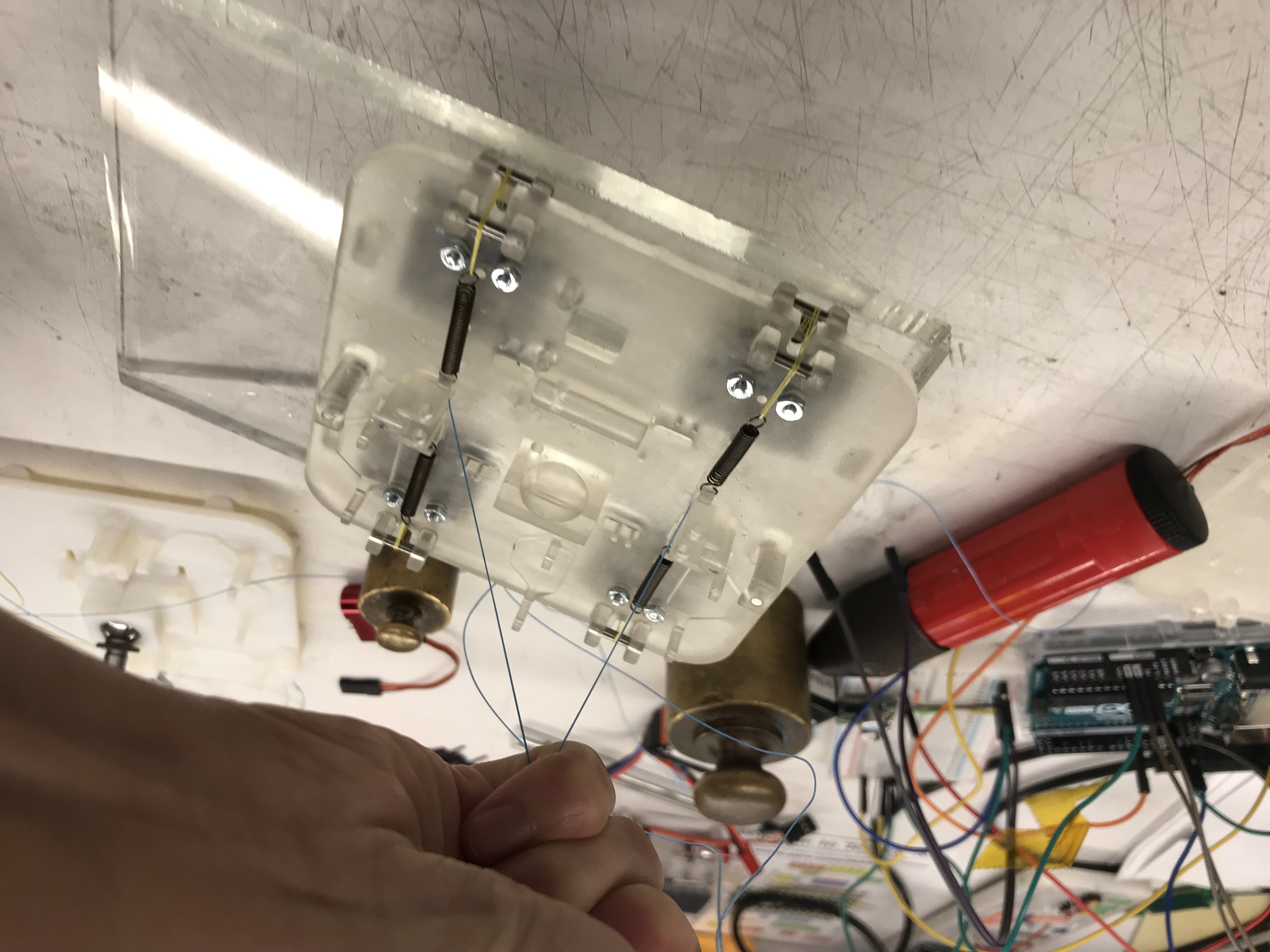
Top view of gripper with tied wrist tendons
Wrist tendon tying jig attached to gripper
During the end of last week, I was mostly trying to improve the sensor testing set up in order to measure the exact distance from the sensor to the material. Originally, I had used a pretty simple set up and lined everything up by eye. Although this worked okay for the original testing, I don't think this would give us the preciseness we are looking for, especially if we are hoping to get a measurement that is plus or minus 1mm of the actual measurement. I think that if we want it to be more precise, I should laser cut a base with slits at the exact measurements we are recording and some kind of mount for the sensor to firmly attach to. Additionally, I changed the code I was using to test the time of flight sensor. I added a for loop so that it only will give you one averaged reading every 10 seconds. It takes the average of 500 readings because I concluded this to be enough times to get a consistent average. I may also upload these values into Matlab or Excel in order to better analyze the sensor's trends. Although my method for obtaining data points is now more accurate, I still get a message saying "raw reading overflow" at a distance of 184mm, which is under the expected maximum distance.
I've also been designing a jig in CAD that will hold the gripper wrist stable so that we can tightly tie all of the wrist tendons. The jig I designed constrains the gripper's rotational motion and motion in the x and y direction. Once I created the jig, I made an assembly in Onshape with the entire gripper and the jig to ensure that it fit properly. After I confirmed that the parts were the correct dimensions, I 3D printed the jig using the Object printer. The jig includes a base plate with threaded holes so that the 4 stands with through holes can tighten onto the base. The top portion of each stand is precisely dimensioned to clasp onto the edge of the gripper. I considered adding a set screw to the top clamp, but the clamp was tight enough on its own to properly constrain the wrist's motion.
When I finished with the jig, I was able to successfully tie down all of the tendons to their corresponding servo while the wrist was stabilized. Once the Arduino code for the gripper is uploaded onto the Teensy, each servo should be able to tighten or loosen its tendons, activating and deactivating the adhesive mechanism.
Week 9
August 17th, 2018
I finalized my sensor testing set up and am now getting consistent readings for each material. I marked several distances on a piece of acrylic and mounted the sensor a fixed distance away. Also, I have noted that the sensor may need sometime to calibrate before obtaining accurate readings because it is less accurate right after it is rebooted.
I tested the sensor at distances from 5-50mm, testing at every 5mm increment. I only tested a smaller range this time because we only need the sensor to work from close distances in order to function properly on our gripper. On each of the materials, including aluminum, glass, clear acrylic, colored acrylic, wood, and frosted acrylic, the sensor gave varying accuracies. In conclusion, I found that more opaque surfaces worked better, such as wood and colored acrylic. After doing some research online for why these inaccuracies might still be occurring, I found out that increasing the size of the material increased the accuracy.
Week 10
August 23rd, 2018
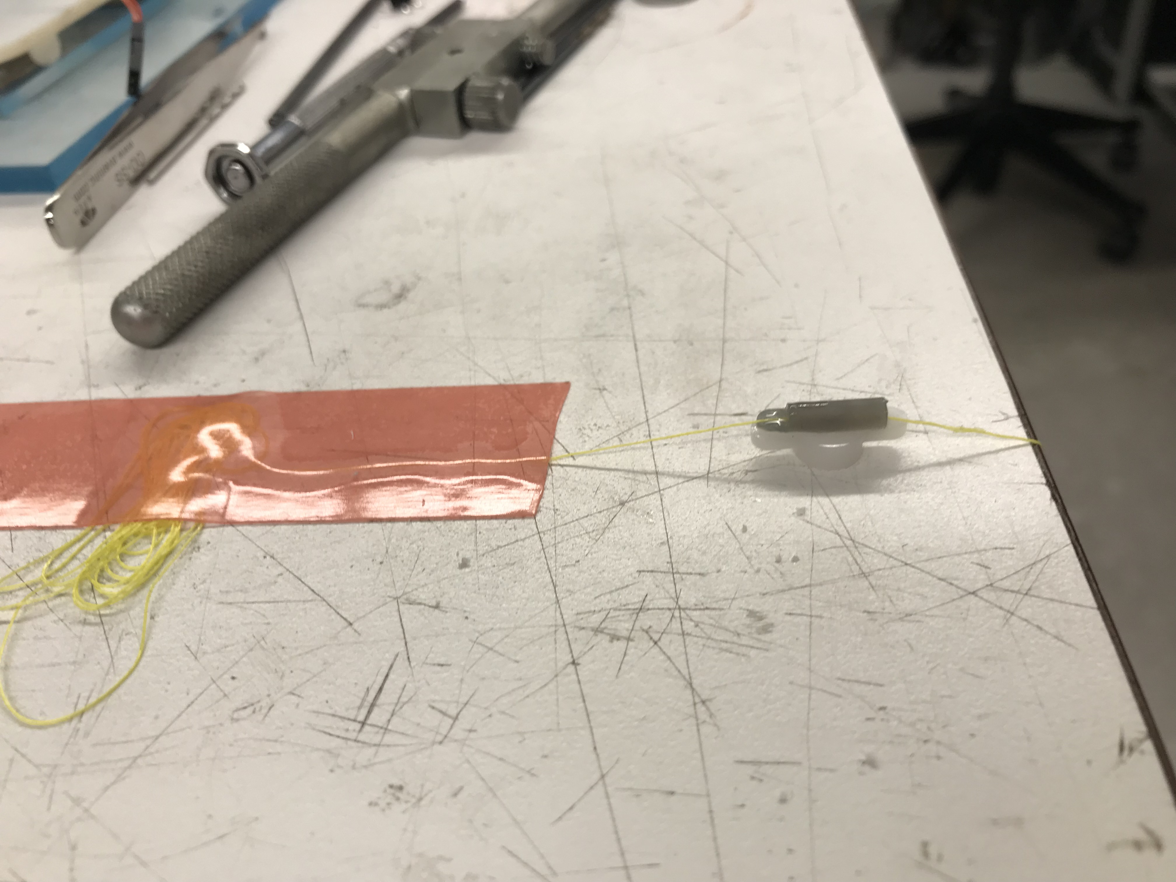
Close up of tendon clamp
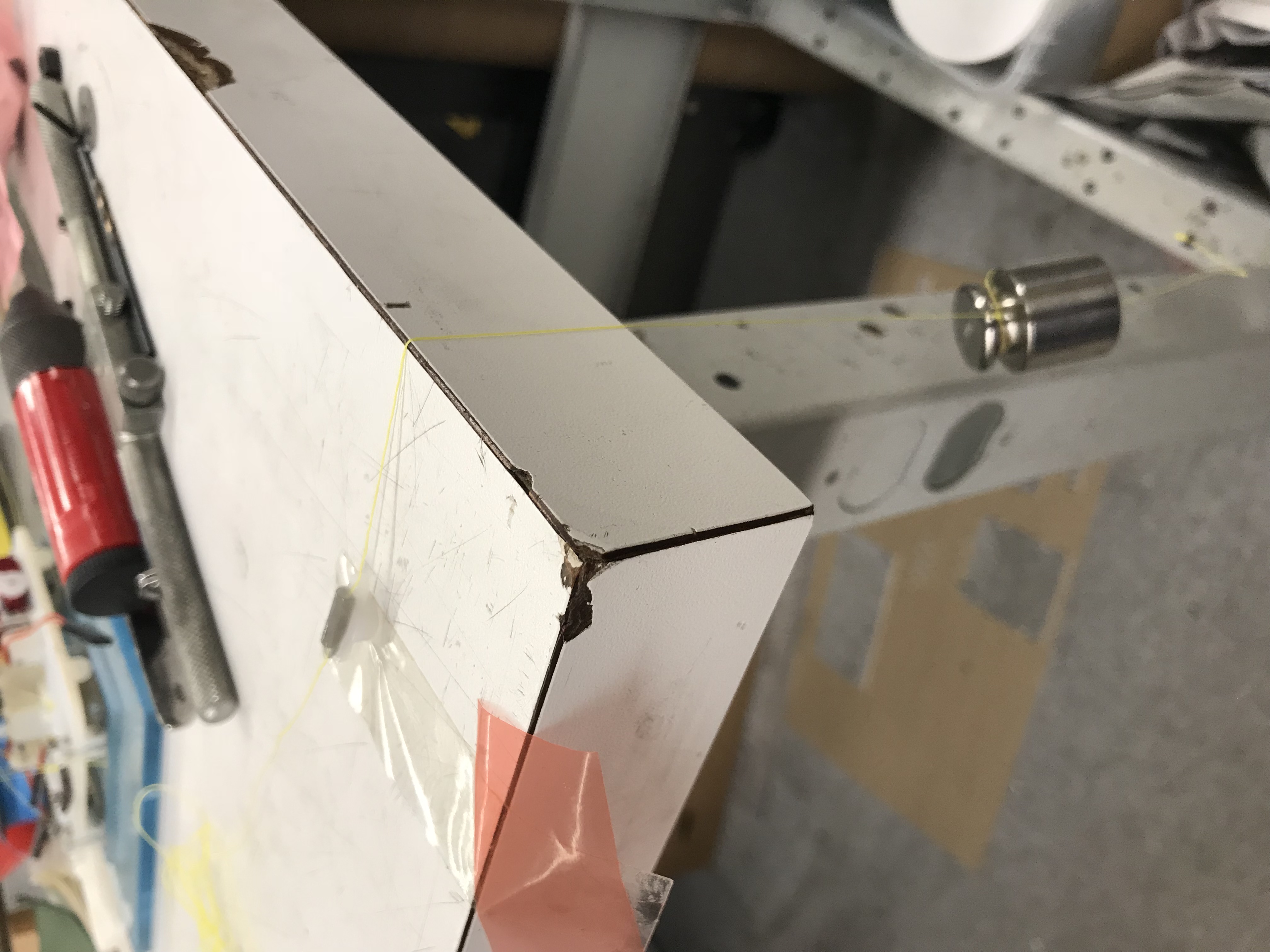
Tendon clamp testing set up
This week was my last week of the SURI program and tomorrow we will be presenting our posters summarizing the work we did over the summer. I spent most of this week and last week working on the the poster and preparing it to be reviewed by Mark and the rest of the BDML at lab meeting. Because I had some extra time after I finished poster edits, I helped Tony and Arul test their new idea for clamping the tendons securely onto the servos. After we 3D printed the clamps, I fed the tendons through the clamps and taped holes into the them so that we can insert super glue through the sides and secure the string once it is positioned correctly. In order to test how well it clamped, I hung a 100g weight from the other end of the tendon to see if it would slip. The tendon did not slip so we will now use these to clamp the tendons onto the servo horns.
PWM servo driver circuit
I've also spent the last couple days assembling a circuit and writing the Arduino code to test a PWM servo driver with 16 channels for servos. I only tested it using 2 servos, but we only needed to assess the resolution for this servo driver. I concluded that the resolution was high enough for what we are looking for because I was able to adjust the code so that the servo horn should move 1 degree and when I tested it, it did move exactly 1 degree.
Here is a copy of my SURI poster and a picture of the most updated version of our gripper:
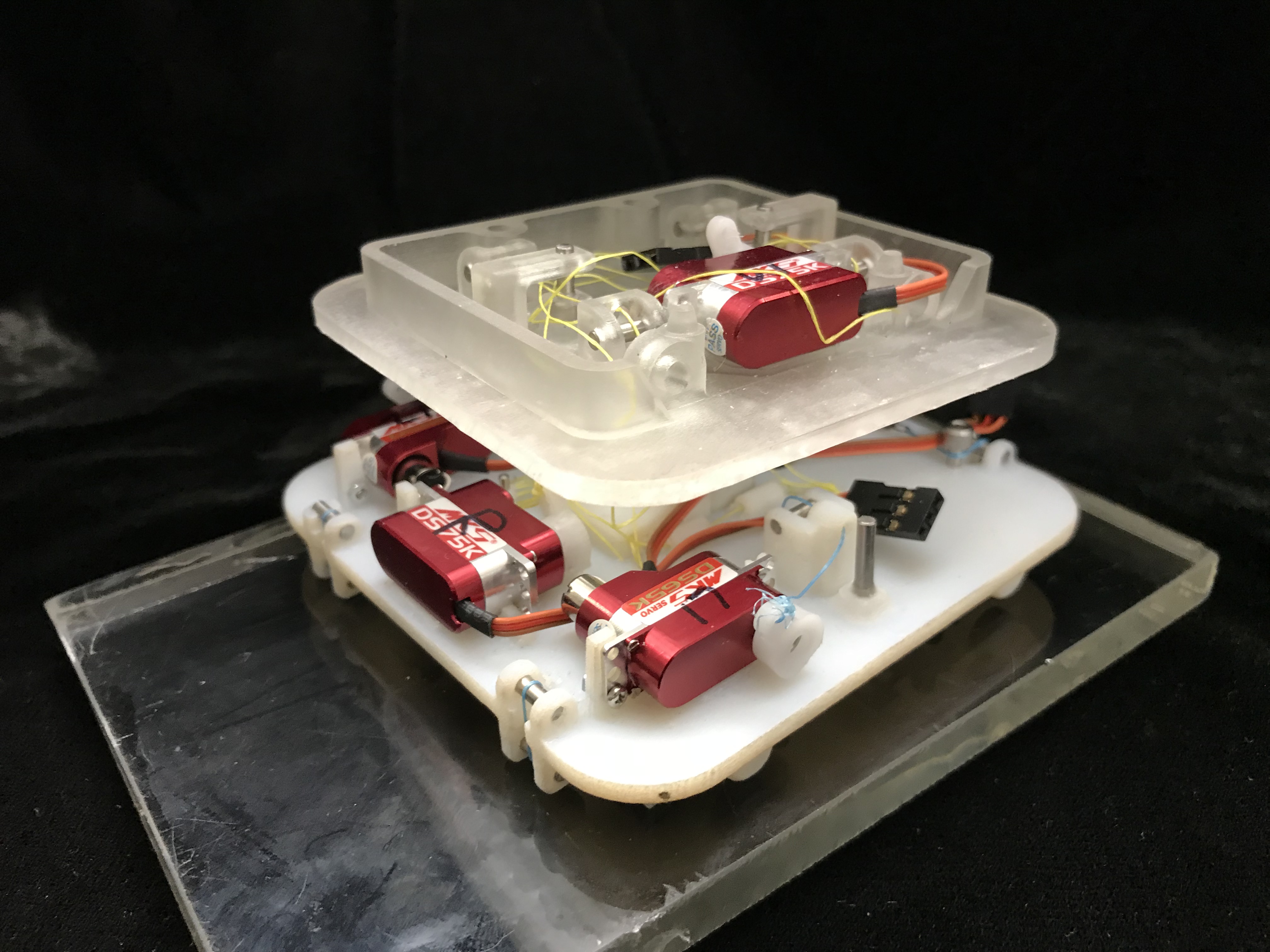
Gripper with just the wrist and palm
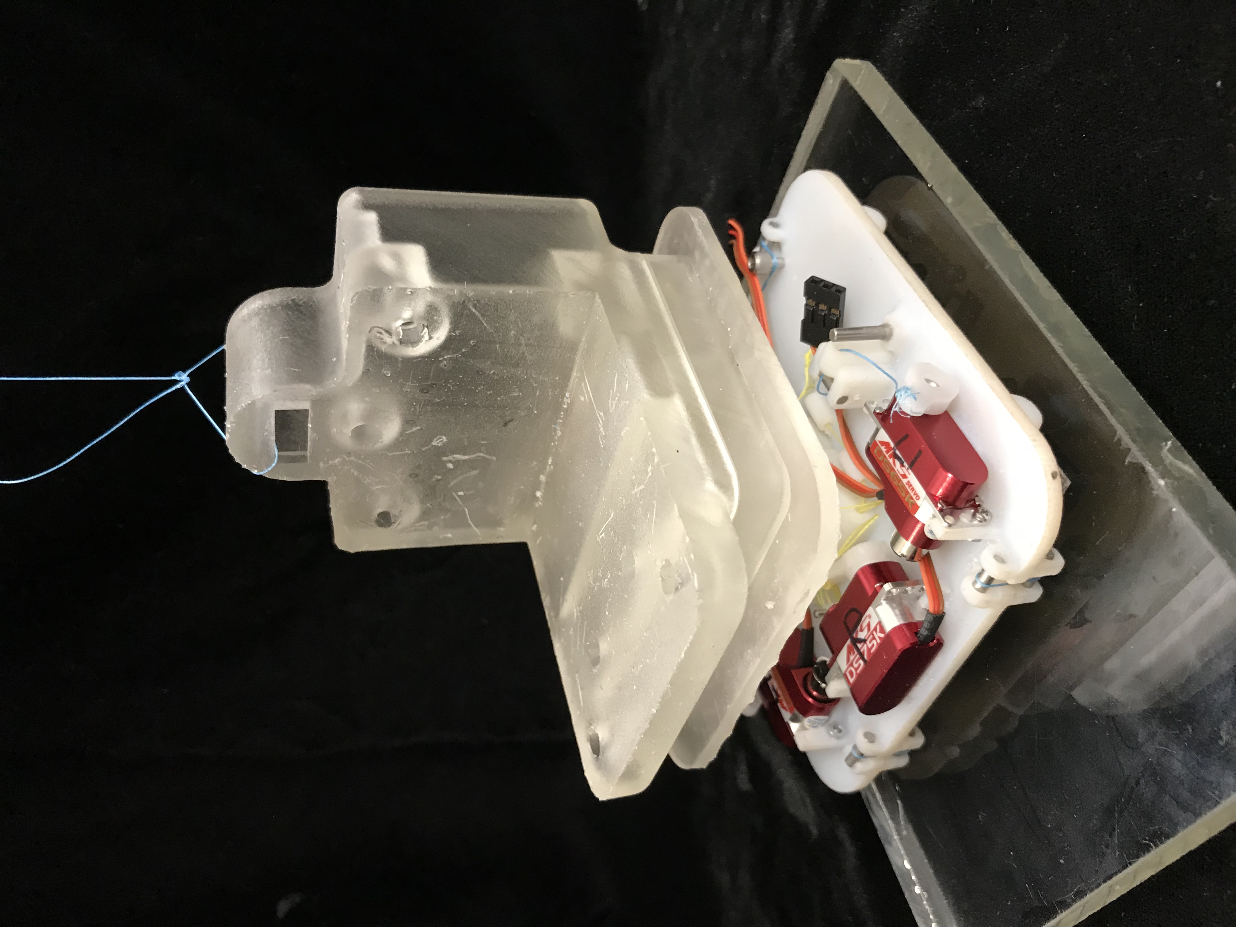
Entire gripper with piece attaching to Astrobee arm
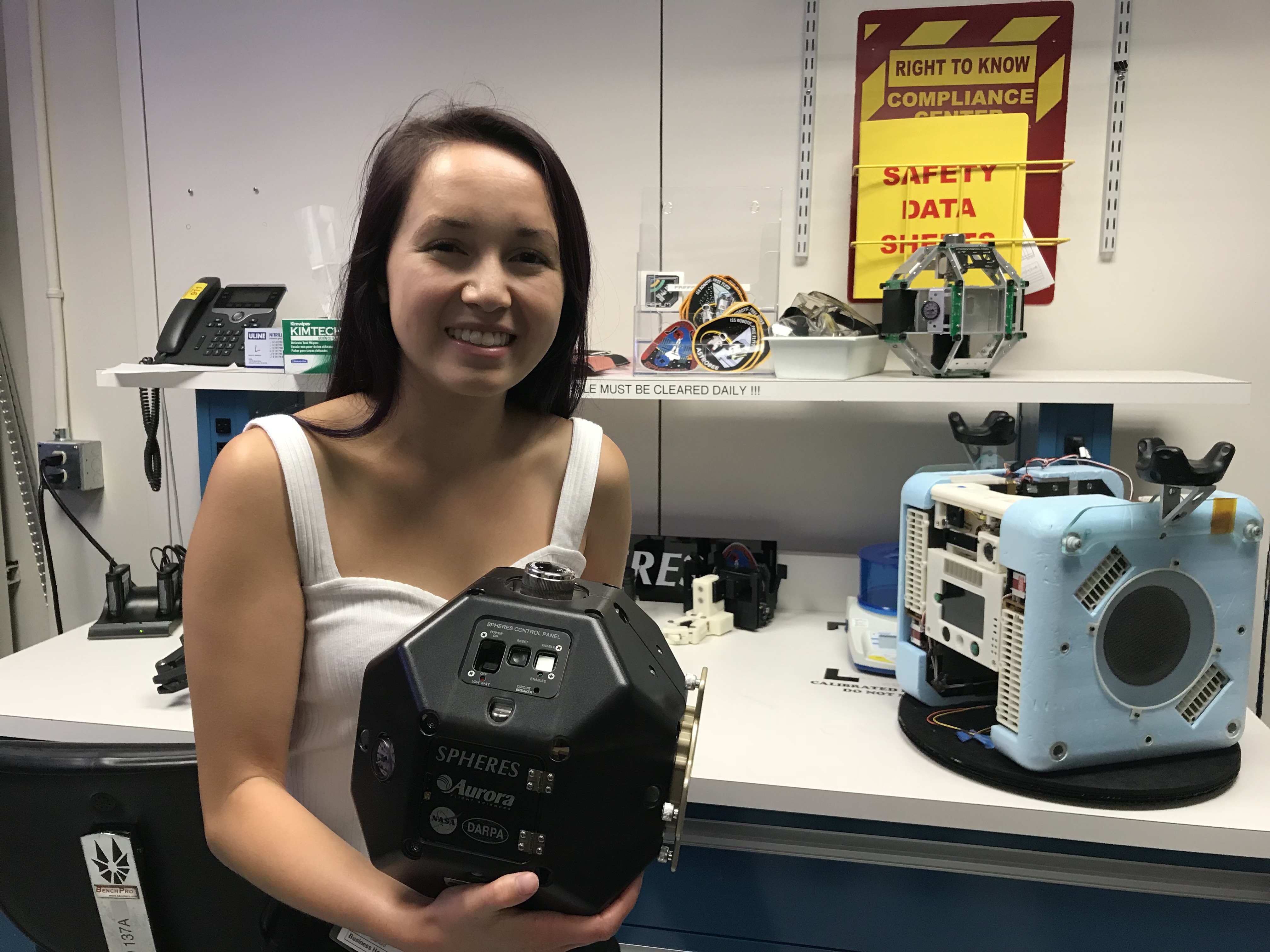
Me touring Ames and holding a robot from the
SPHERES program with an old version of
Astrobee in the background