(redirected from Profiles.IansBlog)
---- Week 10 ----
Wednesday August 26th, 2015
Final Post:
This summer I learned a lot more than I thought I was going to. Over the past few summers I've picked up various skills by trying a wide range of projects, but they all felt like very hollow knowledge. By the end of those summers I didn't actually know how to do anything new. I could use a variety of machines and programs, but I wasn't an expert at anything. As a result I didn't feel comfortable being an authority on any particular subject. For example, I learned a lot about ArcGIS last summer, but if something went terribly wrong I didn't know how to fix it. I had learned a process but I didn't understand the program. Beyond that, ArcGIS is not particularly useful in daily life, and is something I have a hard time explaining to people outside of the environmental realm.
With my project this summer I can say I learned something extremely useful and I learned it well. I can debug most things on the Arduino platform simply by how the Serial port fails. I know a lot of the ins and outs of processors and microcontrollers, and have solid experience going deep into the world of digital sensors. My general coding skills have also greatly improved. Having to code for someone else has refined a lot of my commenting and organization practices. Also, after being exposed to a variety of hardware and software bugs, I feel that I can move through device projects a lot faster now.
This was by far the best internship experience of my life. Not only was my project fun, the people I worked around were fun to work with. The lab culture is a model for what I want my next job to be like.
Thank you to Mark for taking me on at the last minute. I know it was inconvenient but it has been so important to my career and life in general.
And thank you to Caitlin for giving me a project I could have a lot of autonomy over. I apologize if my progress seemed slow at times, but your patience with me gave me the confidence to really take the time to learn the system and make decisions I could stand behind. This was the perfect combination between my BioE major and my CS interests.
I had a lot of fun this summer and I hope everyone's projects go well. Thanks again to everyone for the help and mentorship throughout the summer!
Monday August 24th, 2015
This morning I made my poster and went over some data with Caitlin. We found a couple problems when porting the code over to her computer, but we got the process down and now the code works fine. Everything seems to be falling into place with the product. In order to prepare for the first trial Wednesday, I'm adjusting the attachment mechanism to attach to shoe laces.
---- Week 9 ----
Friday August 21st, 2015
I presented this morning at lab meeting and I thought I was able to articulate my project fairly well. I wasn't perfectly clear about what data was in the slide (specifically about the fact that the motion capture data was my baseline) but otherwise it went smoothly. This week I've mostly been testing edge cases and I'm starting to get a little tired of it, but I think one more half-day of closing off weird bugs should be good. I still can't figure out why the IMU's tend to be more erratic and inaccurate at times, and then almost perfectly accurate at others. To be honest I'm not sure I have the ability to fix this problem, especially because it seems to be a hardware issue (the software is not changing between trials). Hopefully I can figure it out before I leave.
Wednesday August 19th, 2015
Yesterday I got everything together, and am successfully saving to the SD card. Throughout the day today I continued to improve the code by leaning out the code that we no longer needed. I completely updated the user interface and created protocols to save multiple files (and name them sequentially) as well as delete multiple files.
Monday August 17th, 2015
This morning I implemented my new plan for integration with a slight tweak. After talking through the problem with Chris on Friday I decided to change the serial port connection to the slave FSR Arduino. I wasn't sure if this was possible, but after trying it out this morning IT WORKED. Our system is now integrated and I just have to tweak the protocol for saving the data. Hopefully the sensors behave and we can get some good data over the next week!
---- Week 8 ----
Friday August 14th, 2015
BBQ tips for next year
Things we did right:
--Stay under budget. We used Cash and Carry in San Jose to buy our food and we were able to purchase 63 pounds of fairly high quality meat for under $100.
--Marinate the pork. If you use pork or any other non-ground meat, please marinate it. It will taste delicious.
--Veggie burgers. Include these, people appreciate them.
--Have enough food. We planned for 150 people but only about 80 - 100 showed up. That said, we hosted our BBQ late in the year, so BBQ's hosted at the beginning of the year may have higher attendance.
--Speed. We had served everyone by 12:40, mainly due to our preparation the night before.
Things we didn't do right:
--Too thick of pork cuts. If you plan on using non-ground meat, get the SURI's together and a few newly sharpened knives and cut the meat into as thin of slices as possible. You should aim for 1/2 inch thick slices, but if they're thicker than 3/4 of an inch they will likely be too tough for people to eat on a bun. That and they take much longer to cook all the way through.
--73% lean ground beef. If you are making hamburgers I suggest you go to Costco and just buy their frozen ones. If for some reason you decide that's not what you want to do, you need to buy 90% lean ground beef, and you need to pack it EXTREMELY TIGHT and EXTREMELY FLAT. Burgers tend to fall apart when they are not tightly packed. As for the lean meat percentage, it's not only healthier but it's also less greasy and provides you with bigger burgers after cooking. Your burgers will shrink to insanely small sizes if you do not purchase high percentage lean meat ground beef. That and it will create a huge pool of fat on the sheet metal in the grill that is likely to catch fire.
--Started grilling to late. We began grilling an hour early and the only reason we had everyone served so fast was because 150 people didn't show up. Had all of the people shown up we would have been in big trouble. Begin grilling your non ground meats an hour and a half early at the latest. Grill your ground meats starting at least 45 minutes before.
LAST AND MOST IMPORTANTLY --Bad BBQ's. We used the PRL BBQ's which have all infrared burners. If you are experienced in these types of BBQ's, go right ahead and try to use these, but first make sure the drip tray/burner is completely cleaned off, and cook over aluminum foil if you can. If you are not, STAY AWAY AND JUST USE CHARCOAL. Its much easier. The grills refused to get much hotter than 350 degrees, but when they did the sheet metal that acted as a burner/drip tray would ignite the fat from the burgers and jump the grill to 700 degrees. For awhile we were cooking in a grease fire, and were burning lots of burgers on the outside while the inside remained raw. The fire was so big at one point it jumped out of the grill and caught a knife lying next to the grill on fire.
Thursday August 13th, 2015
I spent most of yesterday trying to get the code to work with a two hour break to re-enter and re-label the waste disposal bag which had been rejected by EH&S. For a few hours I was attempting to work with the new data transfer method. Unlike Serial.print, the new method required data to travel in bytes or arrays of bytes, so I couldn't just send raw floats across the bus. After awhile I decided to send the data as a c-string, which is an array of characters each one byte long. After some searching I found a float to string conversion method and I was able to successfully transfer data across the I2C bus. Unfortunately at around 3 I tried adding pull-up resistors to the circuit (because the full circuit wasn't working) and the code stopped working. I wasn't able to get the code back up by the end of the day.
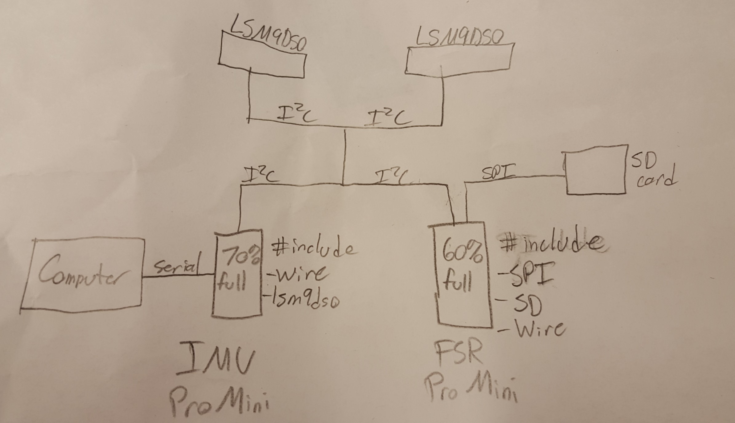
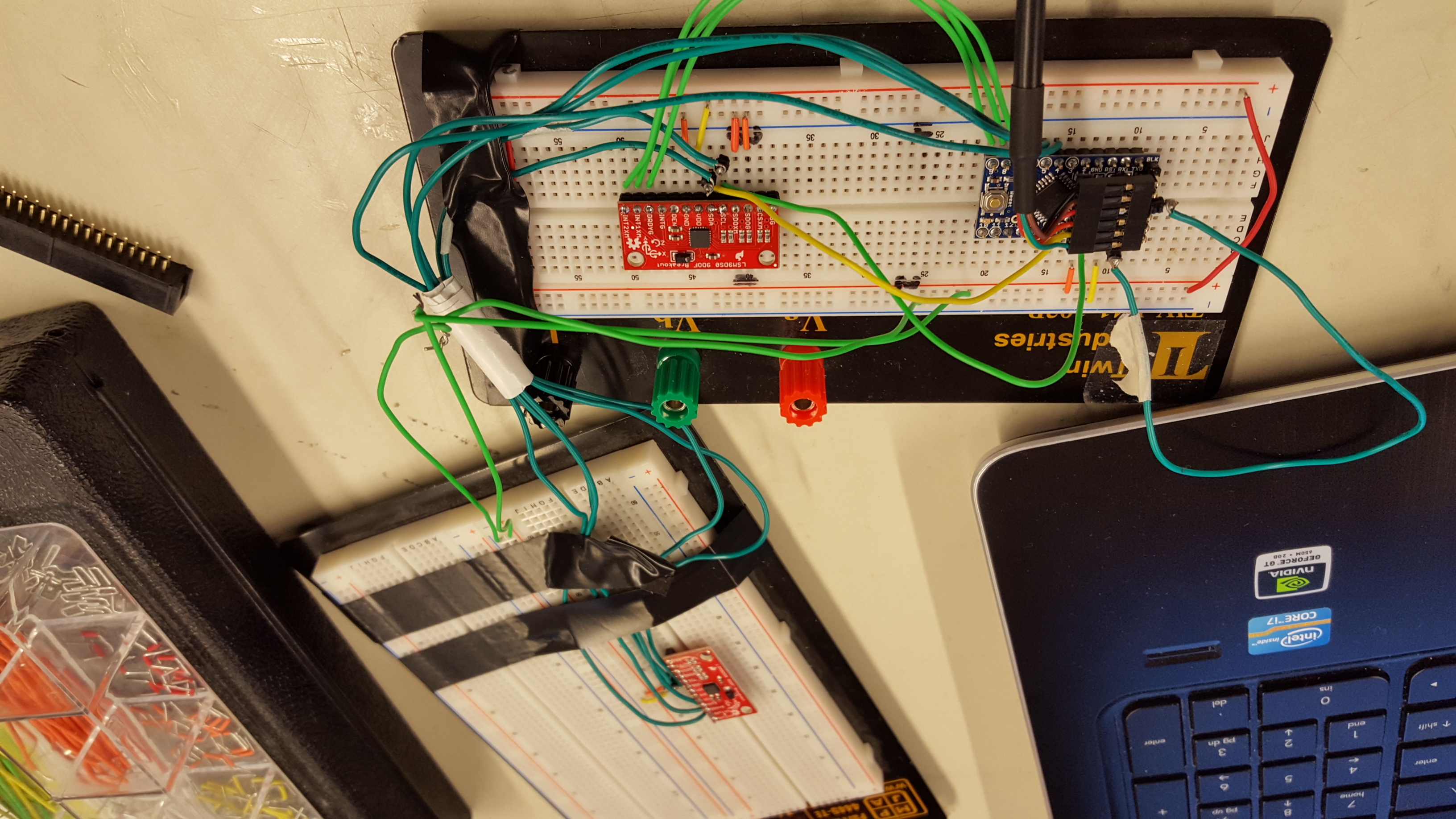
This morning however I began to dive into more research about using I2C with 2 Arduinos and I found that the master had to have access to all of the slave devices, and it requires a rather time consumptive protocol to switch an Arduino from Master to slave, something that cannot happen at 100Hz. The other option would be to upload all of the IMU library info to the FSR Arduino, however we would probably run into storage problems again. I decided to switch the code to use the IMU Arduino as the master, however due to space problems I would still have to store the data using the slave FSR Arduino. The final system will have the IMU Arduino commanding all of the devices, but it will send its data to the slave FSR Arduino for final processing and storage of the data. Hopefully this system works:
Tuesday August 11th, 2015
Yesterday I continued to characterize the accuracy of the sensor. Unfortunately the sensor seemed to act erratically, sometimes giving really good data, and others giving weird, totally different data. I wasn't able to fully understand why the sensors were changing so much but I had a feeling it has to do with the fact that there's no auto-reset. Today though we got in the new USB boards that have an auto-reset feature that hopefully should reduce the amount of inconsistencies in the data. Today we also started integrating the IMU and FSR systems together. After combining the code and compiling I realized we were using 125% of our available storage...so we moved towards the idea of using two pro mini's to expand our memory capacity. I thought about looking into processors with larger memory but quickly found they were all much larger and more energy consumptive than two pro minis. I spent some time deciding which Arduino should be the master, and ended up choosing the FSR Arduino. Its data is more complex while the IMU Arduino could send a single number upon request. By the end of the day I had the code together but it didn't work.
---- Week 7 ----
Friday August 7th, 2015
This morning before lab meeting I finished my IRB required CITI certificate for Nonmedical Research Investigators and Staff allowing me to test subjects with the device I made if we get to that point before I leave this summer. After that we had lab meeting and flammable cabinet cleanup. Unfortunately a lot of the chemicals were dubiously labeled and poorly contained (ferric chloride was in a Naked Juice bottle), so it took awhile to sort everything out. After that I focused on improving the attachment mechanism for the IMU system to prevent slippage and hopefully reduce the variability in our data (see the figure from Thursday). I'll have to test out how much of a difference this made on Monday.
Thursday August 6th, 2015
This morning I was able to get the accelerometer working and after a series of tests was able to confirm a final setting: Gyro set to 500 DPS and Accelerometer set to 4G. One of the trials was a bit funky but the rest seemed pretty consistent.
Wednesday August 5th, 2015
After the IMU data turned out so bad yesterday I began to mess around with the data collection rates on the sensor (speeding them up). After a few trials I got the sense that 500 - 2000 DPS would probably make the best collection rate, however soon after switching the settings around the accelerometers stopped working. I was able to get some great angular velocity graphs, but unfortunately without the accelerometer data it was hard to get angle data. This has happened before while debugging the code/processors over the past few weeks so after an hour or so of not being able to fix it, I figured I'd just wait it out. I went to meet with Caitlin and see how post processing was done on the motion capture data.
Tuesday August 4th, 2015
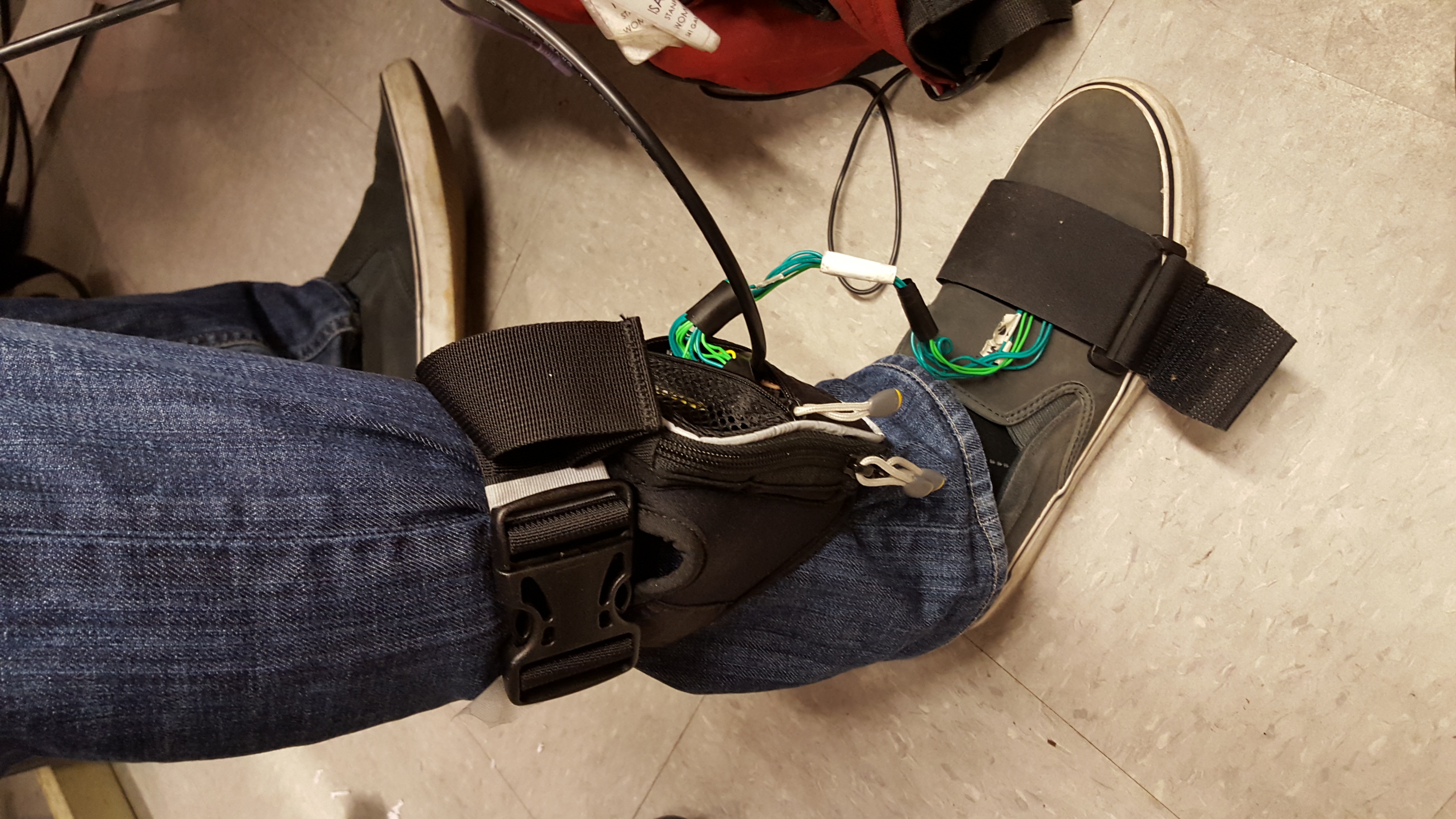
Yesterday I upgraded the IMU attachment mechanism, creating something that could easily (and comfortably) be clipped to the leg with nylon straps. This has made testing so much easier, and wasted a lot less electrical tape:
Before:
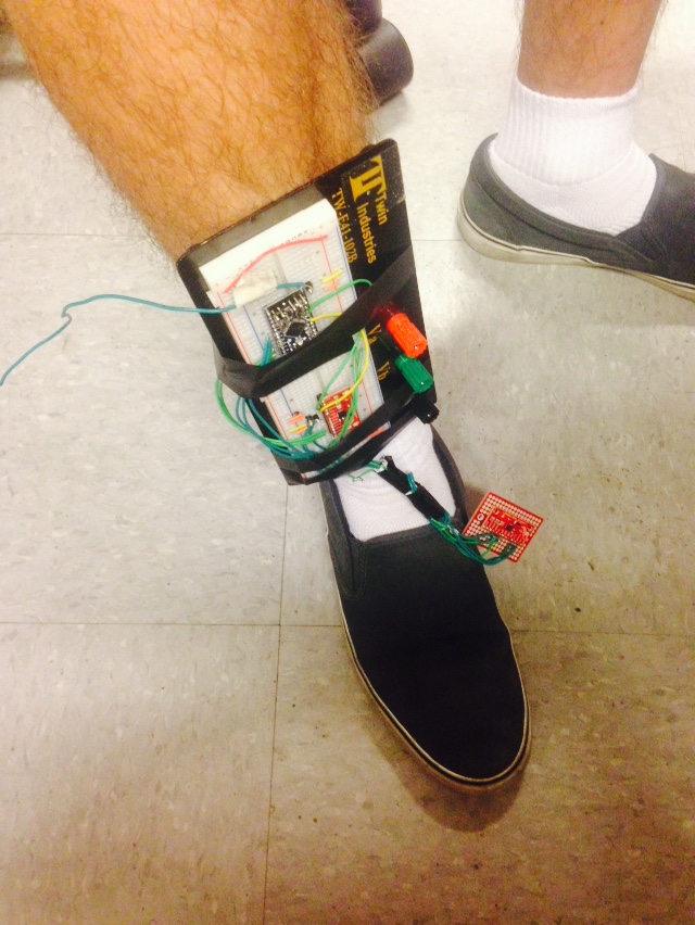
After:
Moving from there we went to the motion capture lab and ran some tests so we could get a basic idea of what my gait looks like and whether or not the sensors were in the right ballpark. Unfortunately the IMU data turned out to be terrible, but we were able to get some great stuff from the motion capture lab.
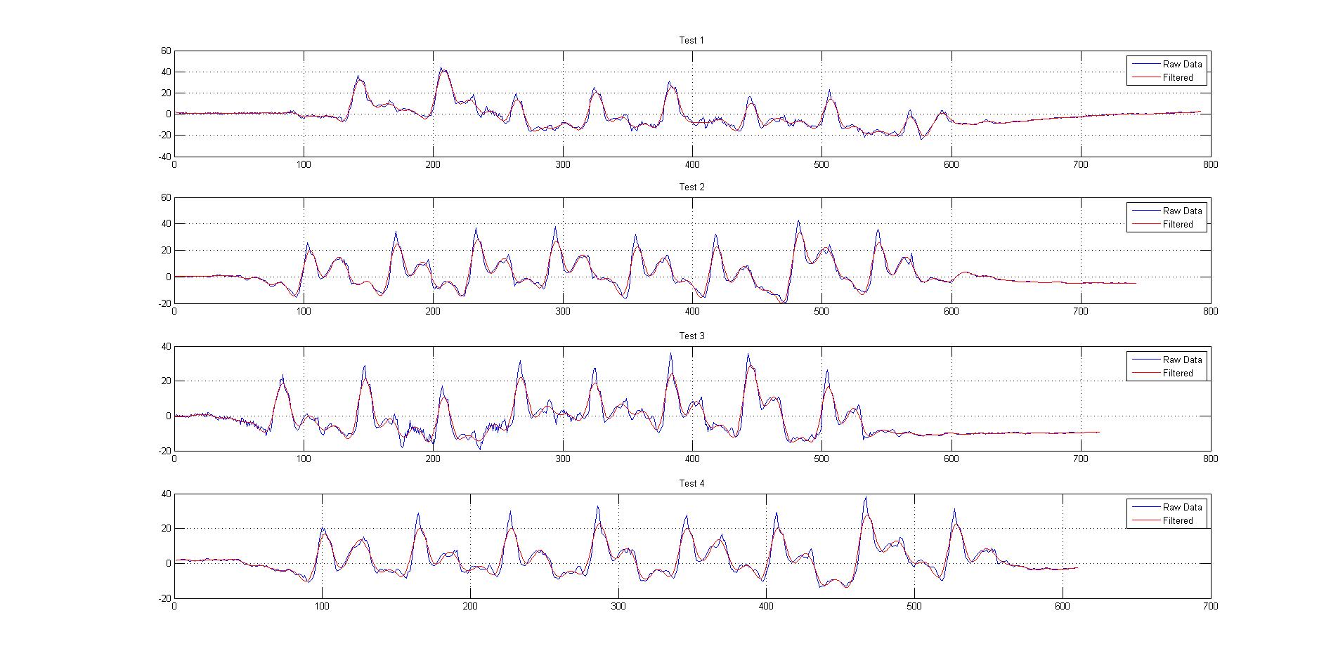
Monday August 3rd, 2015
Today and Friday have been much more exciting days than the past few weeks. After I got the sensor working Caitlin and I began to test its capabilities. On Friday we ran 4 tests that seemed to show an extremely accurate sensor that could show the differences in a couple different types of gait. The walking patterns were great, the noise hardly needed to be dampened, and the angles seemed to be spot on.
It all looked very promising until today, when I fired up the same code and suddenly the pitch reading seemed to max out at 90 degrees. By "max out" I mean that the sensor cannot tell when its upside down or right side up. In other words, the measurements start at 70 degrees and as you continue to tilt the sensor up, go to 80, go to 90, and then go back down to 80 and 70. It's interesting because we didn't see this behavior on Friday, so either we totally missed something and our data is just a lie, or something changed in the sensor. I think it may have to do with the orientation of the sensor because the orientation also didn't seem to be a problem until today. We ended up trying to get some tests done with roll however it didn't work out that well, mostly due to the fact that strapping the breadboard to my leg sideways required much more tape and continuously fell off. At the end of the day I ended up getting another breadboard from Caitlin and minimizing the design so that tomorrow we can run some real tests on the IMU and not have to worry about the attachment mechanism.
---- Week 6 ----
Thursday July 30th, 2015
This morning was frustrating again, but I'm confident the Pro Mini's will work. They were created by Arduino and running almost THE EXACT same processor as the Uno, and they have verified testing by the developers of the code. Working through the voltage problem I found the correct pins that need to be wired up, the correct voltage, and...
12:09 PM PST we have liftoff.
IT WORKED FINALLY.
...and of course the Wiki wants to put this particular picture upside down. I don't know why. Moving on to designing the final soldered piece and the SolidWorks housing.
Wednesday July 29th, 2015
Today I focused a lot on research while I waited for the Pro Mini to come in. I looked for quantitative measurements of the effects of Botox on patients with cerebral palsy or those recovering from stroke. There was a surprising lack of quantitative data, which I guess makes sense since the company we're working with wants to get it so bad. When the Pro Mini came in I began to hook it up to the sensor. According to the datasheet for the Pro Mini it had a voltage regulator that could handle up to 12 volts, however I plugged it in to the IMU with 5 volts from my computer, and within 10 seconds the IMU caught on fire...not sure what is happening but I cannot believe they sent us the wrong board after all this.
Thursday Update: They did not send us the wrong board. Caitlin checked the EAGLE file and found that the VCC input into the board from the FTDI port does not pass through the regulator...a feature they should have been a little more explicit about.
Tuesday July 28th, 2015
The past few days have been sad. On Friday I got nowhere trying to debug the code, and without a debugger or print statements it didn't give me many options for finding the error. As a safeguard we ordered another processor Friday afternoon in case the TinyDuino wouldn't work out (BTW we ordered one day shipping and it's still not here due to Sparkfun not shipping it until 7:00 on Monday, and a "Mechanical Failure" at UPS). It wasn't until Monday morning that I found a NULL pointer exception causing a conditional memory error that overwrote the memory the Serial.print port was using, causing the Serial input to break. At first I was ecstatic, this was probably one of the hardest times I had ever had with a computer bug and I had finally found it.
The next thing I did was run the code and...it failed again. The hardware address on the TinyDuino hadn't changed. I spent all of Monday trying to find the way to change the address resistors. The Tiny Circuits website said I needed to cut the address resistors and so I began removing the resistors from ground and it didn't work. I ended up making 3 cuts on the one board and 2 on the other in every combination of cuts I could make, and still the address wouldn't change. It wasn't until Tuesday morning that I realized the resistors they were reffering to were actually a LACK of resistor. The schematic was showing connections that weren't there. As a result I realized the Tiny-Circuits website was wrong in stating that you need to cut the resistors. Instead you actually needed to connect them. Luckily I was barely able to repair the cuts and with a little extra soldering was able to change the address of one of the boards. Finally I was ready to put it all together and run the code and begin taking useful measurements to see if the IMU's would work for us and...once again it failed. This time the code just paused and never read either of the IMU's data.
I went back and ran the original fragile code on one of the IMU's (the code works on one IMU at a time, but was freezing when trying to alternate in the same code) because I wanted to see if the IMU would work well when being moved around and played with. It drifted considerably. As always I got a system message that there was no compass calibration data, and I looked through the code and confirmed that the compass was in fact still being used, regardless of whether or not it was calibrated. Not only was this a huge flaw in the code, it meant that the drift I was seeing was happening DESPITE referencing the data to a magnetometer. After not being able to get the IMU to work by the end of the day, I decided that we needed to move away from the TinyDuino platform. It hadn't helped and was only taking more and more time as I kept finding new bugs. Besides the new processor we had ordered was finally coming in tomorrow so I'll move to that in the morning.
---- Week 5 ----
Thursday July 23rd, 2015
After some preparation yesterday I'm ready to start putting together the TinyDuino IMU. We got the parts around 10 and I began to integrate the two IMU's into our system. The code worked perfectly when I plugged the first IMU in, and by lunch time I had both working independently with different addresses. After lunch I began to integrate them to work together, a simple process of duplicating part of the code, and the Serial problem I had yesterday began to happen again. For some reason this code doesn't like creating more than one IMU object most of the time. There have been occasional times where I have been able to get it to work but upon running the exact same code again (no uploading just reopening the serial port) the code fails.
Wednesday July 22nd, 2015
Today I was going through all of the code for the Tiny IMU, and upon looking through the code I noticed it had some built in settings for the LSM9DS0, which is the IMU we were using previously. Because most of the code for the Tiny IMU seemed to be plug and play (even with 2 IMU's attached), I tried to get the code running on the LSM9DS0 we had. It was a nightmare. There was some bug with how the code loaded everything and it would break the Serial.print process within the first few lines. Upon further investigation it seemed to be a problem with how the code identified the IMU it was using, but even then the problem persisted when there was no IMU attached instead of throwing the error message it should have. I emailed the developer and he said that the code was only designed to run on the Tiny IMU, so I guess we'll just have to wait and hope the IMU works tomorrow.
Tuesday July 21st, 2015
By the end of the day yesterday, I still couldn't figure out the problem. Even with Natalie's help we only confirmed the fact that the sensor only worked semi-properly when connected incorrectly. So I've decided to move on to using TinyDuino's 9 axis IMU, which should be easier to use and more powerful than the current board we're using. Today I confirmed that these boards would work and I ordered the parts we needed. I continued to design a housing unit for the new circuitry, and I prepared for the arrival of the parts by going through and adding dual-board functionality to the designer code.
Monday July 20th, 2015
This morning I had what seemed like a breakthrough, but upon further investigation only increased my confusion. After rewiring everything I fired up the TinyDuino and all of a sudden it started to work. Not super well, but it was giving semi-responsive data at angles that seemed reasonable. Unfortunately it was very inconsistent, and occasionally behaved erratically but it was a start. Then I noticed my interrupt pins were wired incorrectly, so I fixed that problem and the thing stopped working. I'm not sure what's preventing the TinyDuino from reading the interrupts appropriately, but it seems to be the crux of the problem here.
---- Week 4 ----
Friday July 17th, 2015
Today I spent the whole day trying to get an input from the TinyDuino and IMU. I failed. I tried multiple configurations to no avail, and even tried running it on the old circuit, which works with the Arduino Uno. In order to get that done I had to go on a hunt for 1632 cell batteries, and after an hour of looking around campus, Natalie was kind enough to lend me a few of hers. Still though, the circuit produced nothing. On Monday I'm going to try rewiring everything again to see if I can get even a glimpse of responsive data out of the TinyDuino.
Thursday July 16th, 2015
After spending most of yesterday integrating my and Caitlin's code and prototyping the mounting unit, today we got our parts in. At first things went smoothly. The TinyDuino was easy enough to assemble and after a couple hours of soldering, I had the whole circuit assembled. Then it didn't work. I seem to be getting readings from the gyroscope, but no readings from the other sensors. I un-soldered part of my circuit and replaced one of the old boards back on the old circuit (that has been proven to work) and it worked fine. So after determining that the board is fine, and the code is fine, it was down to the wiring or, less likely, the TinyDuino itself. I replaced the current TinyDuino I was using with another TinyDuino and as expected it showed the same problem. I'm not sure what I'm wiring incorrectly, I simply connected like pins together and declared the interrupts. The problem also seems to be independent of the interrupts, since they can be declared incorrectly with the same result. After another hour I've created a new protoboard that can hook up directly to the old circuit. After hooking the TinyDuino up to the old board, it outputs nothing. No errors or anything, the code just doesn't seem to run. I can't even get a print statement out of it. Officially done for the day.
Tuesday July 14th, 2015
After looking through some more papers, I've confirmed our current design. Many other papers use a sampling rate of 100-200 Hz, and a data recording rate of 50 Hz, which is almost identical to our setup (245 Hz and 50 Hz respectively). In terms of housing the boards, I think a 3D printed box with slots for velcro straps is the way to go. Shoe mounting requires more thought, but we could possibly have a strap with a thin plastic section to provide tension under the shoe. We should also use the 16LED board that comes with the TinyDuino to communicate things like battery life, calibrating sequence, and "ready" status, possibly through a thin layer of 3D printed plastic. For printing the data, I'll create a CSV file that can be uploaded to Excel, that way the doctors don't need to buy and learn advanced software like MATLAB. We can then create scripts to automatically graph and present the data, and because the doctors will have access to the raw data, they can suggest further analysis we can run on the data.
I went over all of this with Caitlin in the afternoon, and we discussed integrating the two systems (force sensors and motion sensors). Our data will be a combination of step-dependent data, and a 50-Hz stream of continuous data from our sensors. In the end we want to have a system that uploads and graphs the desired data on Excel automatically.
---- Week 3 ----
Friday July 10th, 2015
The morning was mainly filled with lab meeting/cleanup, but Caitlin and I created a finalized parts list for the gait analysis system, which will be ordered on Monday. After lunch I looked through research papers to find some of the commonly used parts, however a lot of the specific parts used (aside from the actual IMU) were not mentioned. I did find that many of the experiments had heavy post processing of their data, often opting to transmit raw data and do all of the processing in MATLAB. This was often because researchers needed to show improvements from the raw data using their method of stabilization, however for our needs I don't think this will be necessary. Thinking forward it will probably be useful to have the TinyDuino save angle values to the SD card, and then write a python script to process the values into usable information for the doctors (i.e. graphs, gait simulation, etc). The most commonly used sampling rates centered around 100Hz, which should be doable with the TinyDuino, but can be lowered significantly while still obtaining good data.
I also went through some designs for mounting the IMU and TinyDuino, and since we will be 3D printing the box I opted for an elliptically curved box with a foam backing to give stability to the sensor and comfort to the wearer. The one thing I will have to look into more is the possible medical issues with reusing the foam after it contacted a patients skin. I also figured the case would have to completely shield all of the components so it's easy to wipe down and clean, and more robust for small drops.
Thursday July 9th, 2015
Yesterday I looked through code for the LSM9DS0 and I found a file that contained a lot more functionality using the interrupt pins on the board. After some work I got a really stable signal from one of the boards. Unfortunately when I tried to combine both boards the program wouldn't upload to the Arduino. The Arduino would upload other code, but it wouldn't upload code that correctly used the fusion algorithm twice. This morning Natalie and I tried to debug it for almost an hour and a half and we couldn't figure it out. She gave me some of her Arduinos to try out just in case it was the Arduino at fault, and luckily that was it! The code correctly updated on her Arduino and this is the data that came out of the fusion algorithm while walking:
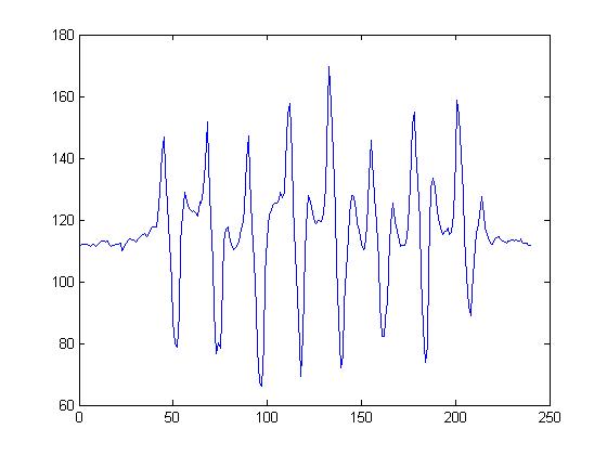
The data was surprisingly stable for the impacts it had with the ground. A lot of the literature cited how they made their moethods super exact, but the data coming from the built in code seemed to have almost no noise and to be fairly accurate. To test it's accuracy over time, Caitlin and I got a goniometer and compared the measurements to a 145 degree angle. The data from that is displayed below, and the error is mostly due to my inability to perfectly line the sensor up with the goniometer. In future trials we will have a solid board I can push the IMU into to make sure its perfectly hitting the desired angle.
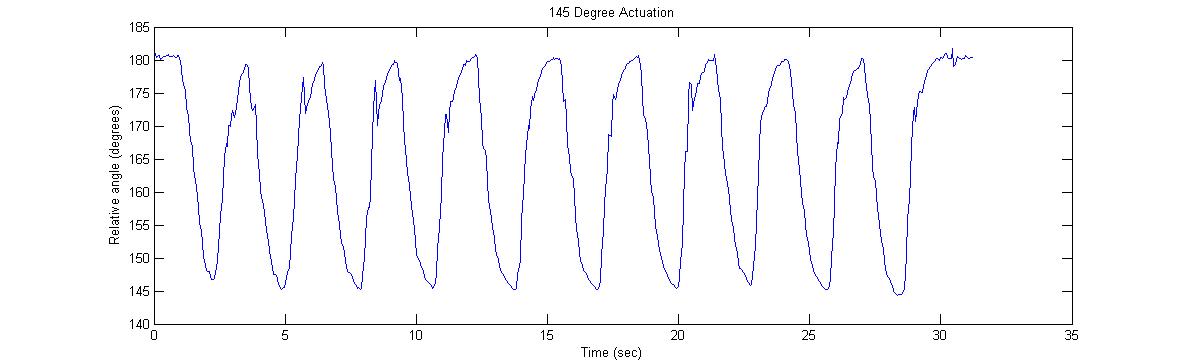
Either than that the data seemed really accurate, contained almost no drift, and corrected itself to the correct angle almost immediately, even after impact.
Tuesday July 7th, 2015
Today I looked through all of the ways to reduce drift from the gyroscope data, and the easiest way seems to be using the magentometer. I think our final solution will probably be a combination of a few methods (the derivative-double-integration method also looked good for cleaning our data) however I couldn't find any real world examples of fusion algorithms. There was also a lot of talk in the literature about using a 4th order Butterworth filter at 12 Hz for cleaning the sensor signals, but examples also seemed hard to find. I'm going to start looking through open source code for other 9 degree of freedom IMU's tomorrow.
Monday July 6th, 2015
This morning I found the problem in the code right away. I had mislabeled one of the data inputs into my calculate function. After fixing this, the code worked normally, and soon after I wrote some code that calculated the relative angle between the two boards. For fun (and for practice) I decided to write some Processing code that graphed the relative angle real time. Unfortunately I couldn't find a good way to permanently save the plots I created, so when I created the first prototype and tested it, I ended up just copying the data into MATLAB and plotting it from there.
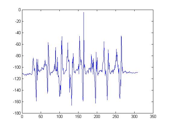
The above data is based on the accelerometers, so from here on out I'll be looking into using the gyroscope for readings, and then looking into what kinds of algorithms will be useful for fusing the data from the accelerometer, magnetometer, and gyroscope together.
---- Week 2 ----
Thursday July 2nd, 2015
The sensors came in yesterday and almost worked right out of the box. Each sensor worked fine on its own, and after looking through some of the ways to change the I2C address of each sensor, got each sensor to almost work independently, however by the end of the day there was still some problems reading the sensor on the other board. Today I found and fixed a wiring problem (mislabeled wires), and within an hour had added switch statements to the code and could receive readings from each sensor independently. After lunch I tried implementing the use of both sensors at the same time, however one of the sensors wasn't giving the right readings. I spent the rest of the day trying to figure out the bug, which after a lot of testing I narrowed down to the new code I wrote just before lunch...
Tuesday June 30th, 2015
I continued to prepare today for the arrival of our sensors. I constructed the breadboard setup and looked through some tutorials on I2C. The main thing that's left to prepare is the final combination of all the data. Tomorrow I'll have to finalize a way to switch between the data on both boards and then subtract the correct pitch vector from the other to determine the angular difference between the two, therefore detecting dorsi and plantar flexion. From there the only thing left to do will be to reduce the noise (and drift) into something the computer can synthesize into useful numbers.
Monday June 29th, 2015
The main thing we did today was order the parts we are going to test later this week. We decided on going with the magnetometer and 9 DOF IMU as initial ideas. The rest of the day was spent getting ready for their arrival. I looked through the code to understand the kind of data we would be getting and how to improve that data with filter equations from the literature.
---- Week 1 ----
Wednesday June 24th, 2015
Today we tested out the 6 DOF IMU. It worked fairly well, and had a pretty cool processing program that showed the sensor's position, however it was clear that the drift was a huge problem upon impact. Short drops of only 2 or 3 inches sent the measurements spiraling. In the end we decided to keep looking for something a little more stable, i.e. 9 DOF sensors. Mark also brought up the idea of using a magnetometer to detect a nearby magnet in order to determine angle, something that would greatly reduce our energy costs.
Tuesday June 23rd, 2015
This morning I researched and brainstormed some more ideas for plantar and dorsiflexion of the ankle. I came up with a possible way to measure ankle angle by using light sensors on the skin to detect the how much the skin is being stretched. Although this was an interesting idea, I didn't think it would provide very reliable data, especially with the poor track record of other optical measuring devices worn on the wrist.
Monday June 22nd, 2015
In the morning we were introduced to the lab and a lot of the projects being worked on. I was really interested in a lot of the projects, but my interest in biotech and wearable technologies brought me to Caitlin, who is working on the insole for stroke recovery. After lunch I got caught up on the causes and effects of stroke, and also watched a few Arduino tutorials to refresh my memory. After meeting with Caitlin, we worked out some extra bugs with the Arduino program on my computer and I set to brainstorming ideas for measuring plantar and dorsiflexion in the ankle.
I really enjoyed being part of the design process. Over the past few summers I've worked at other companies on other research projects, and much of the design work is either already done or handled by more experienced engineers. Although I know I don't come to the best option the fastest, I think I occasionally provide ideas that could be useful to the project. It also helps me understand the project a lot more when I approach it from a design perspective as opposed to a simple task that's laid out.