On this page... (hide)
1. Why Onshape?
Onshape is a full-cloud parametric CAD system that runs in your browser. This means that your document is stored in the cloud, and if you're working on a group project, everyone edits a single copy of the document, real-time. No more sending one person off to do all the CAD or dealing with whether "Version 1 Final Actual Final" or "Final Version 1" is the more recent copy.
Also, since a lot of what we do in lab is laser-cut assemblies, I've written a couple of custom features that make CAD for laser-cut assemblies a snap.
Onshape currently offers all professional features except release management for free with a .edu email address.
2. Getting Set Up
First, sign up for an educational account using your Stanford .edu email address. Note that as of Fall 2017, the education subscription silently expires after 365 days, at which point all your Education-tagged documents become read-only. You can sign up again using the same form to add another year of the Education plan as long as you continue being a student.
If you're used to Solidworks, Inventor, or some other CAD software, you can change Onshape's input preferences to match what you're used to. Once logged in, go to your account preferences page, and under "View manipulation" choose the option for the software you're most familiar with.
Onshape has an Introduction to CAD, more in-depth courses on CAD and data management, and further tutorials to help you get up to speed on using the software.
If you're going to be making a lot of laser-cut parts, you'll want to add the set of custom features I wrote to help do that:
- Laser Joint, which computes and generates finger joints between intersecting plates.
- T-Slot Joint, which creates bolted edge connections between plates.
- Kerf Compensation, which compensates geometry when cutting with software that does not compensate toolpaths for the laser kerf (all laser cutters on campus, at least).
- Auto layout, which automatically lays out parts for cutting using a rectangular bin-packing algorithm.
To add these features to your toolbar, open an Onshape document, and click the "+" icon at the right end of your toolbar. In the "Search documents or paste URL" field, paste each of the above URLs, and add the features to the toolbar. Note: unless you're very interested in writing your own custom code, don't "Make a copy" from the links above; that means you won't get updates to the features if and when I make them.
Each of the links above also points to a PDF containing documentation for each feature.
3. Using Onshape to make a Laser-cut Thing
As an example, we'll go through the process of getting the basic shape of my ME218 project, Big Game Hunting, drawn up in Onshape and then exported to cut on a laser.
3.1 CAD the Geometry
So What is a Part Studio Anyway?
If you totally skipped all the tutorials above (be honest, you did, didn't you?), here's the quick summary of what a "Part Studio" is.
Where most CAD programs have a single part being modeled in a single file, and use assemblies for the physical interfacing of parts and motion studies, this often means that multiple parts that are inherently related in geometry must be modeled separately, or with in-context assembly features, which can reduce robustness of the modeling.
Onshape uses Part Studios to model parts. Each Part Studio can (and often does) have several parts which are closely related in form or function. This allows, for example, modeling two flanges and a bolt circle using a single Hole feature, so that any updates automatically occur on both sides of the bolted joint. Note that parts cannot move in a Part Studio; motion studies should be done in Assemblies. This link is one-way: parts will maintain their positions in the Part Studio as modeled even if the assembly is moved.
Different groups of parts which do not need to be modeled together can be split into different part studios to speed up regeneration time, and then the subassemblies can be test-fit in an Assembly.
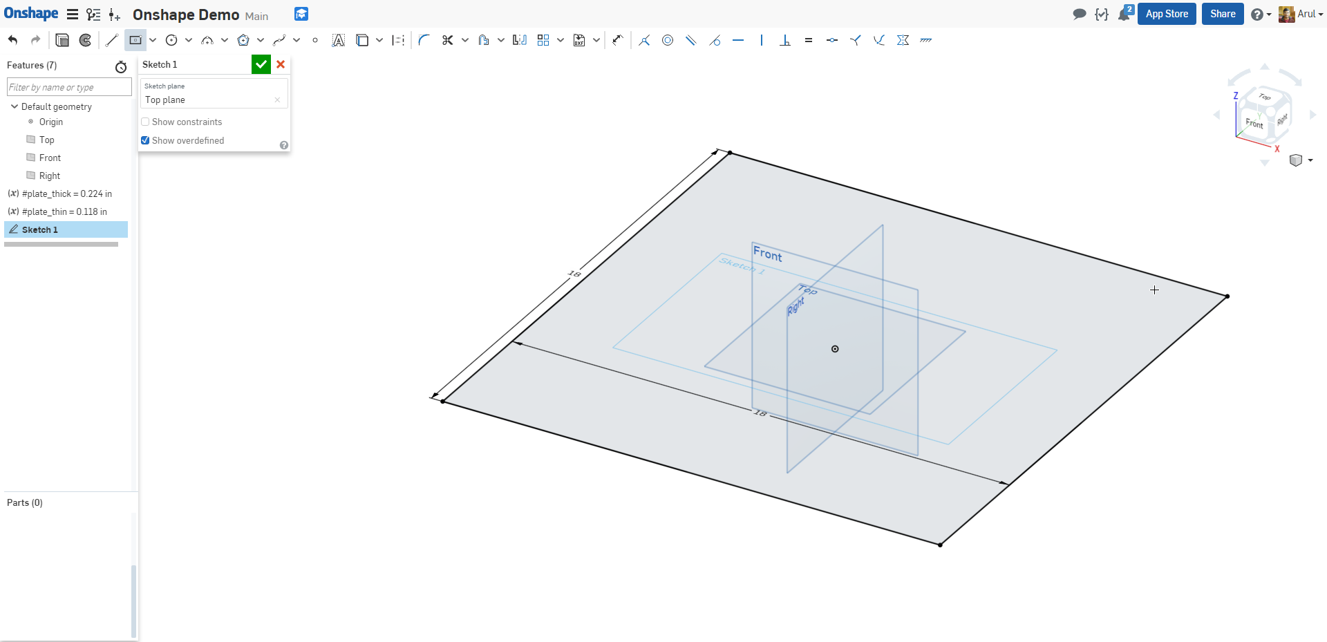
VariablesEspecially when modeling geometry that has specified dimensions, like the board thicknesses for your laser cut parts, it is extremely helpful to first define variables that you can then reference later throughout the design. If you then need to go through and change dimensions because your board is 6mm instead of 1/4", this will make that fix much much easier for you later.
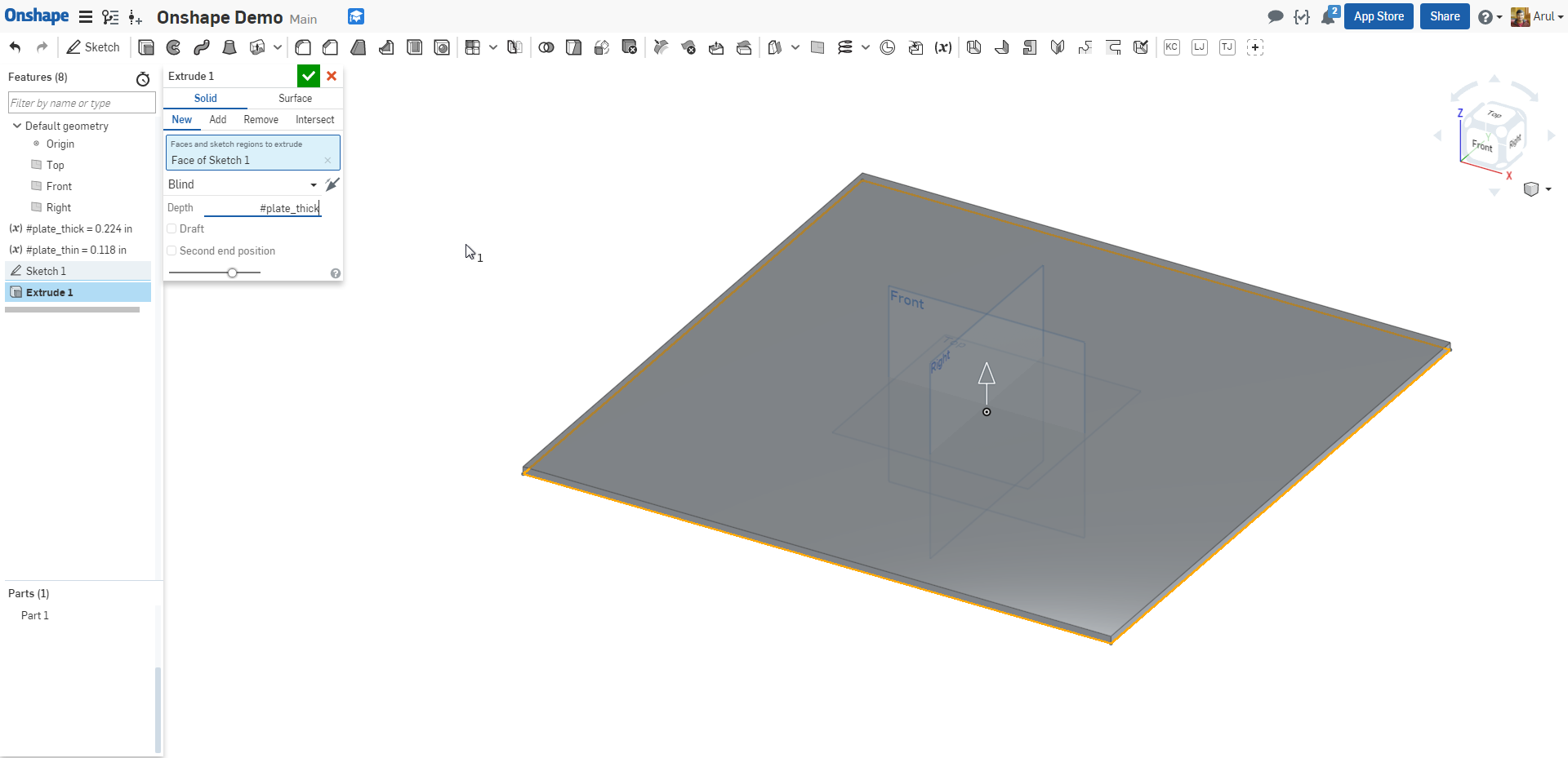
Sketch and Extrude The Base
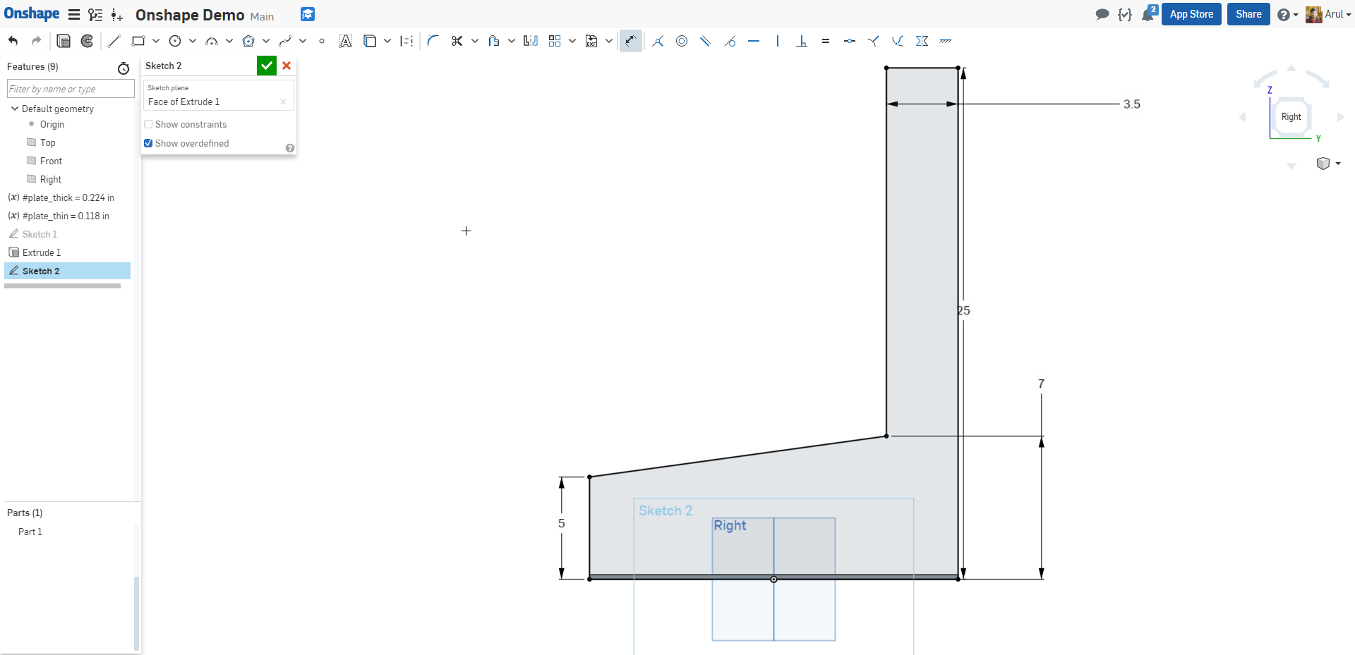
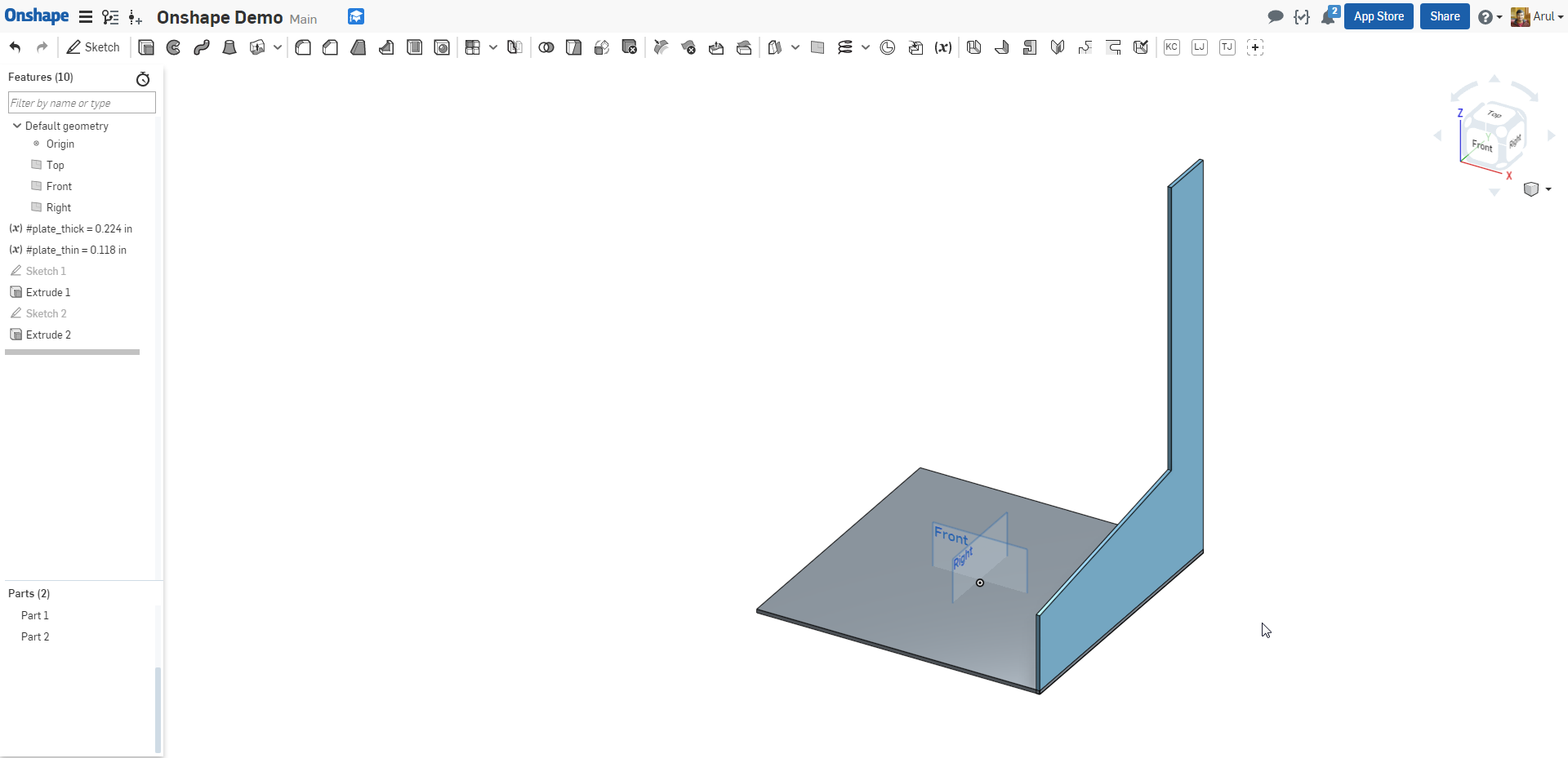
Sketch and Mirror the Sides
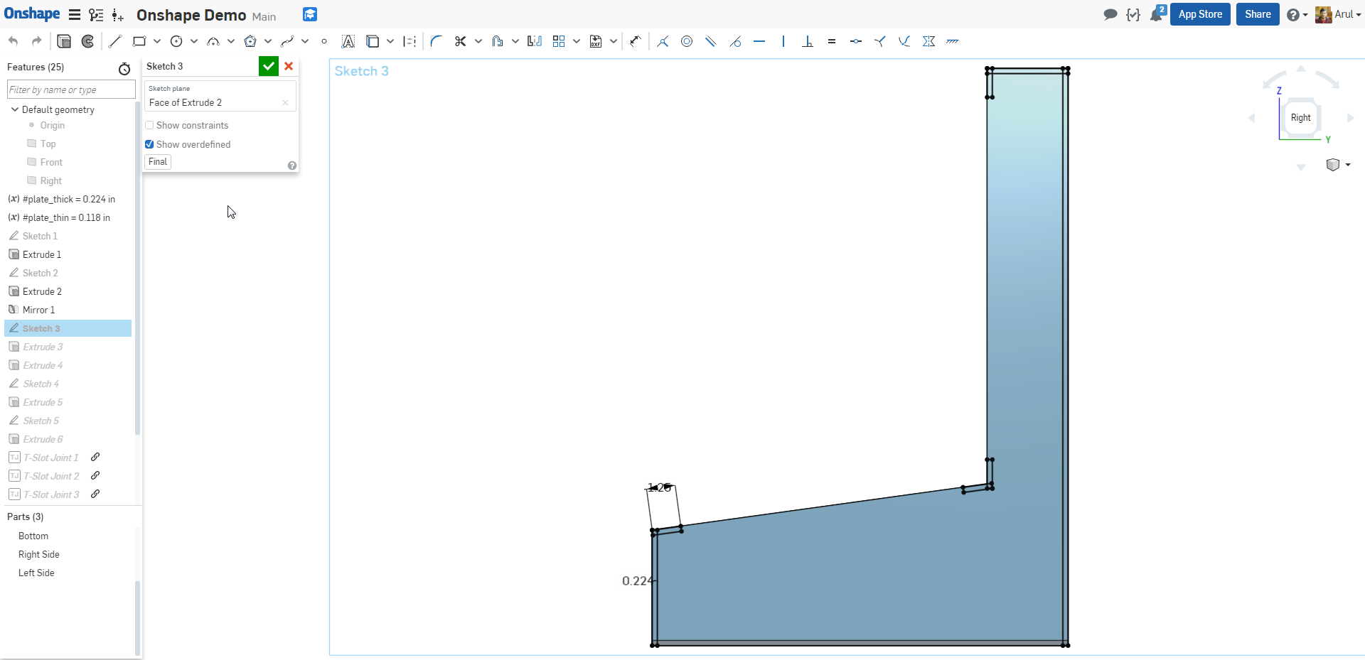
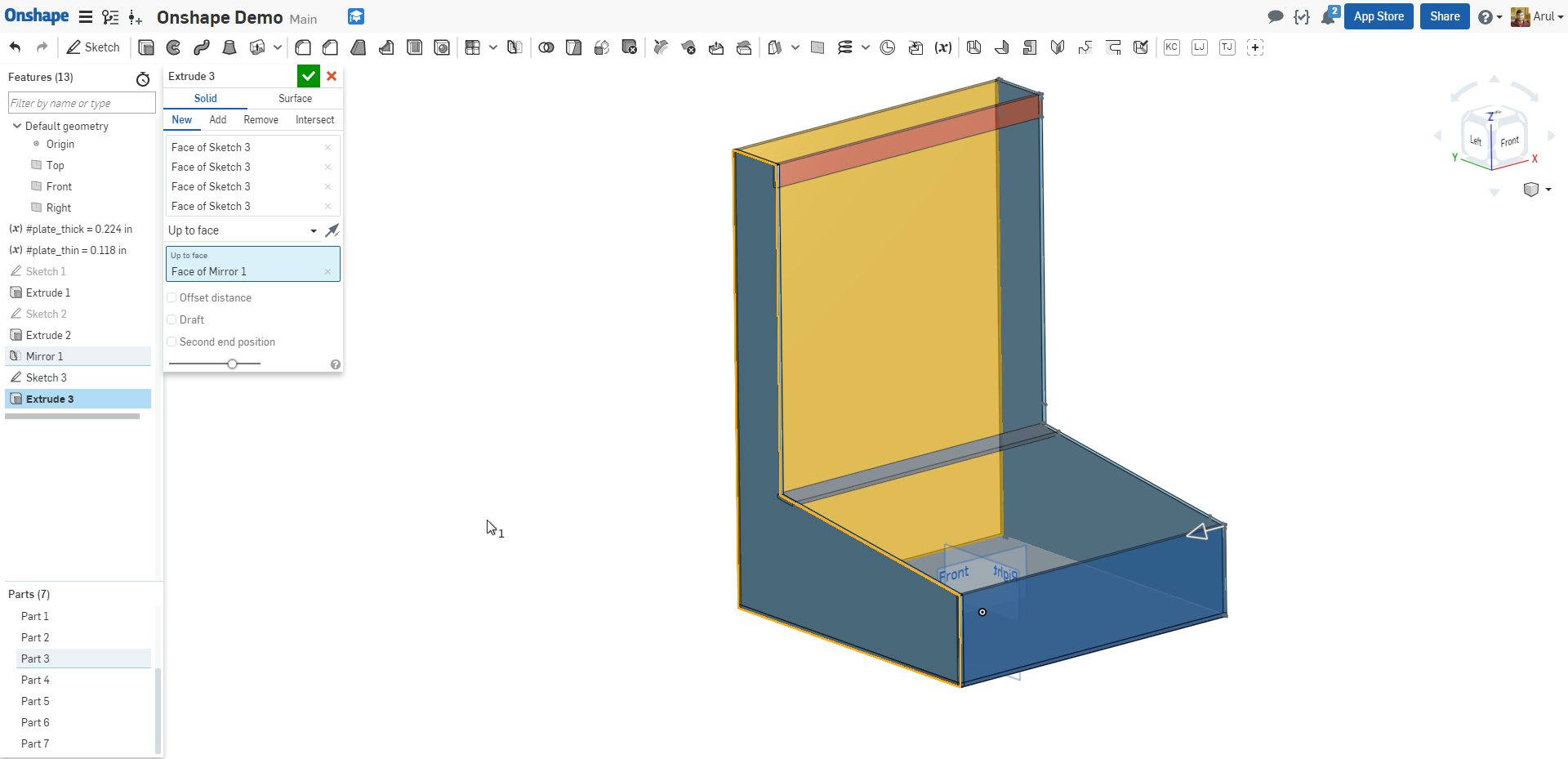
Sketch and Extrude The Cross MembersYou can extrude multiple disjoint regions as part of a single sketch, and they'll all become parts. So for the cross members, we can do everything as a single sketch to define geometry, and then extrude regions from the same sketch in multiple operations.
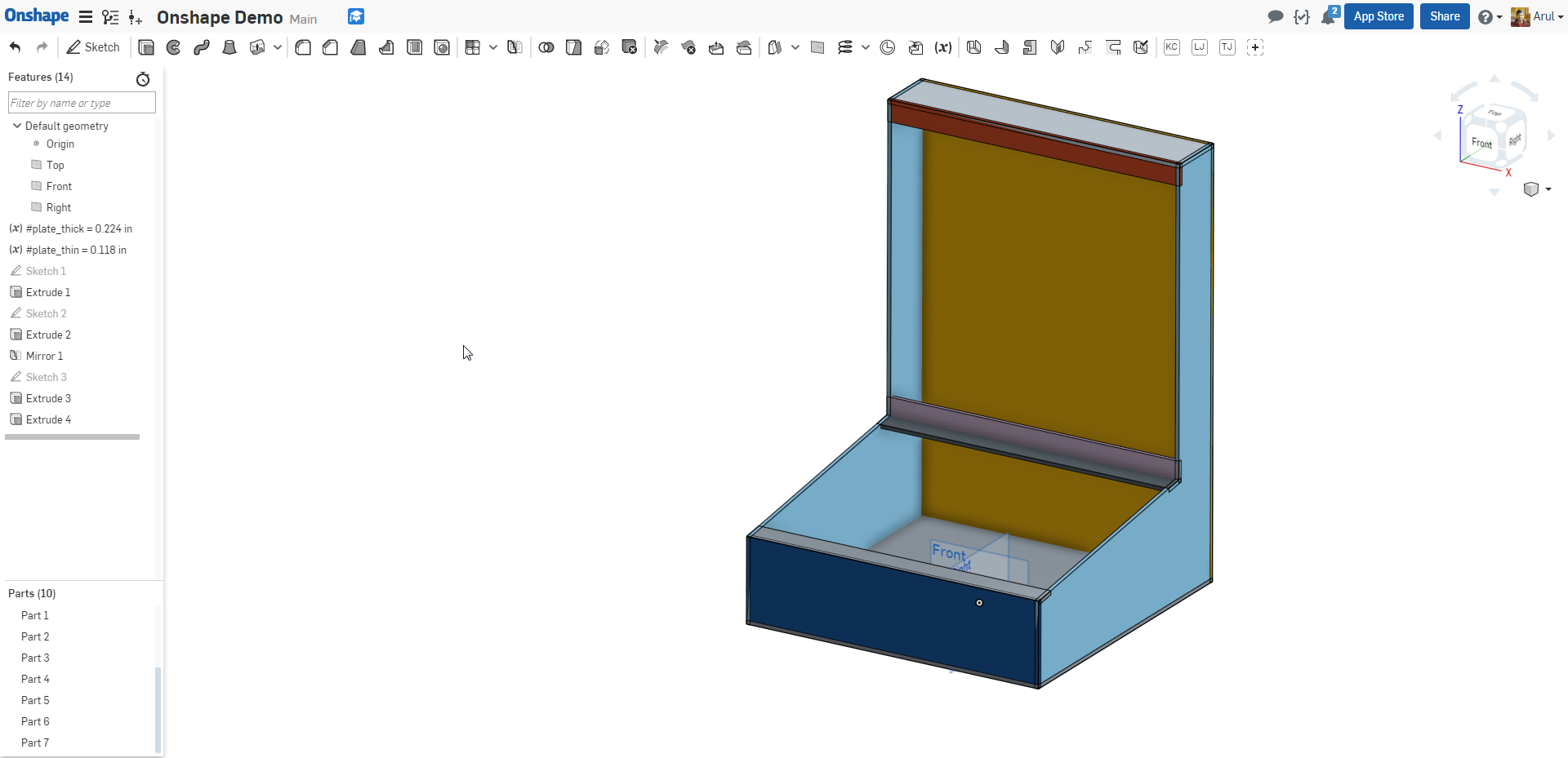
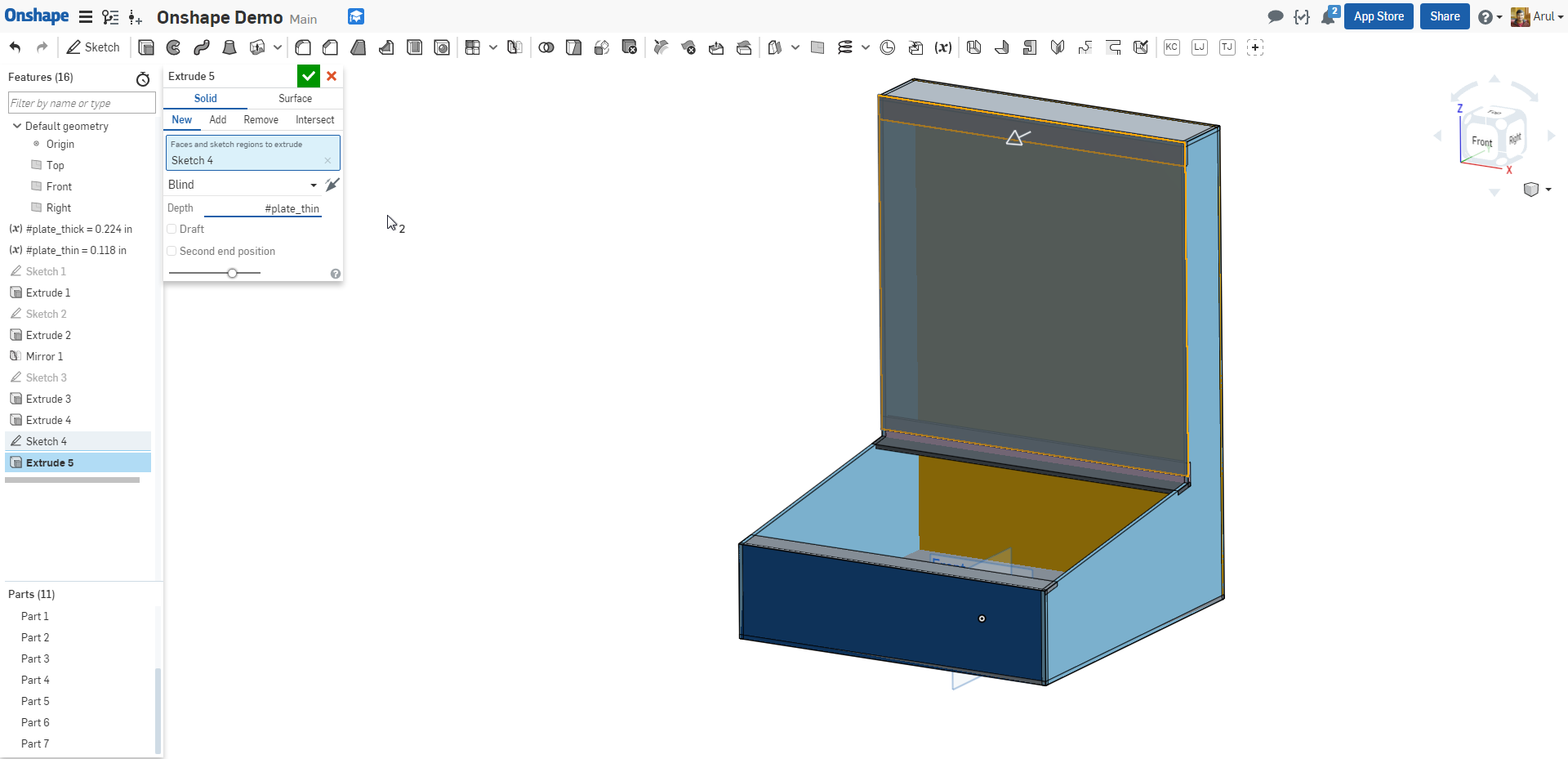
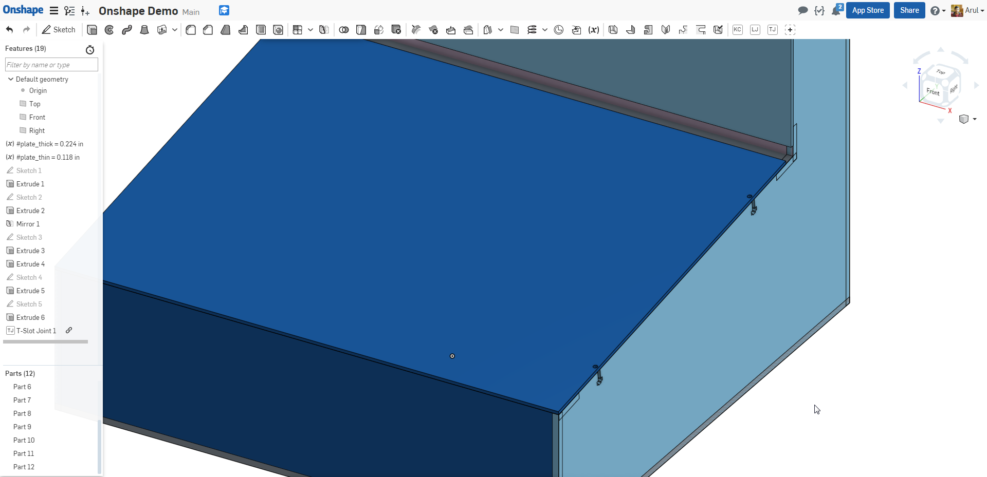
Sketch and Extrude Facing Plates
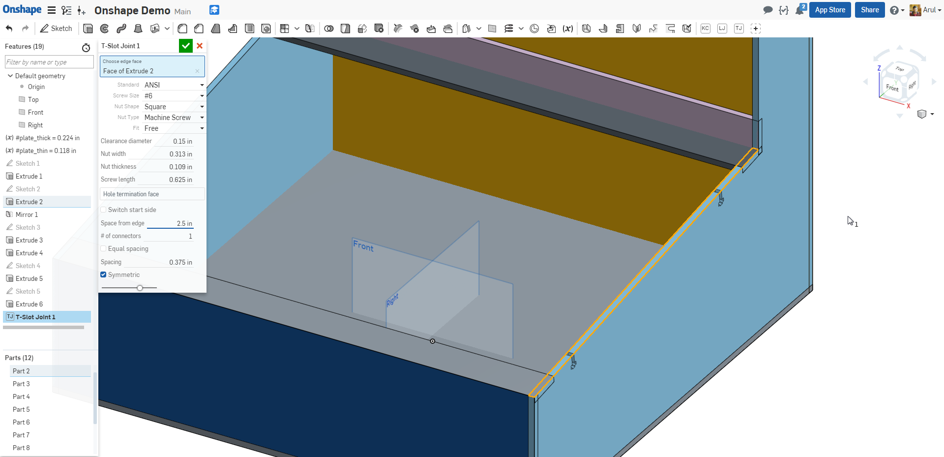
Add T-Slot Connections for the Facing PlatesWe want the facing plates to be removable so you can get at the insides. One way to do this, though by no means the only, is to use bolted edge connections through the facing plates into the edge plates.
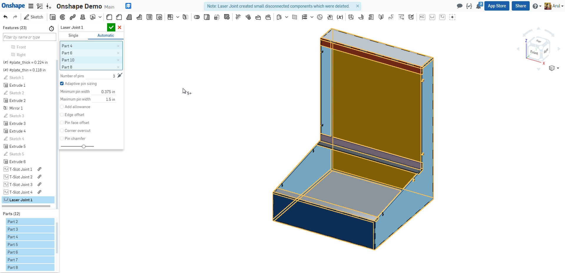
Laser Joint
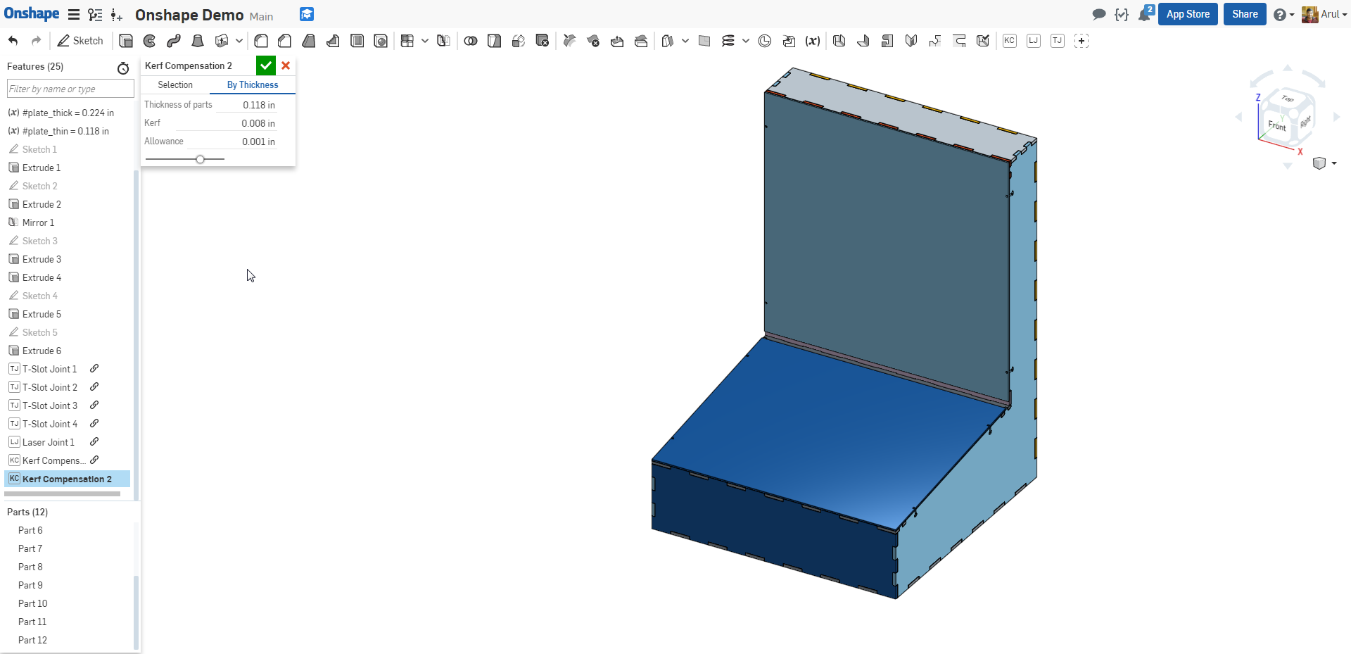
Kerf CompensationThe lasers on campus cut along the centerline. To get nominal-size parts, we'll offset the geometry a little so that everything lines up.
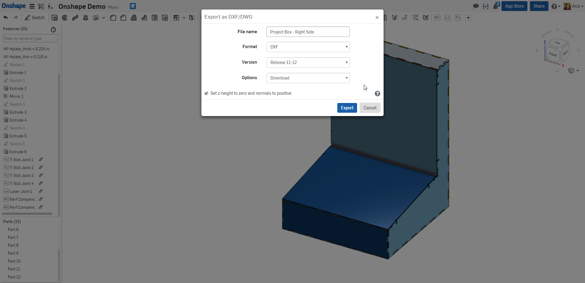
Export DXFs
|
                |
4. Nest the DXFs for Cutting
|
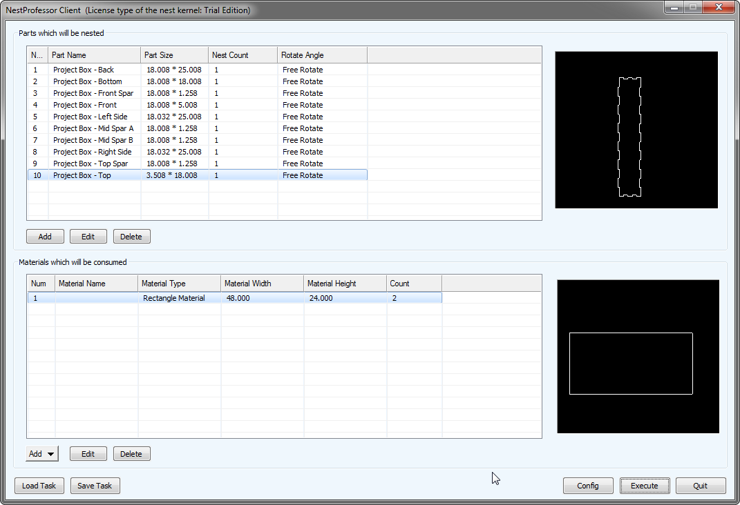
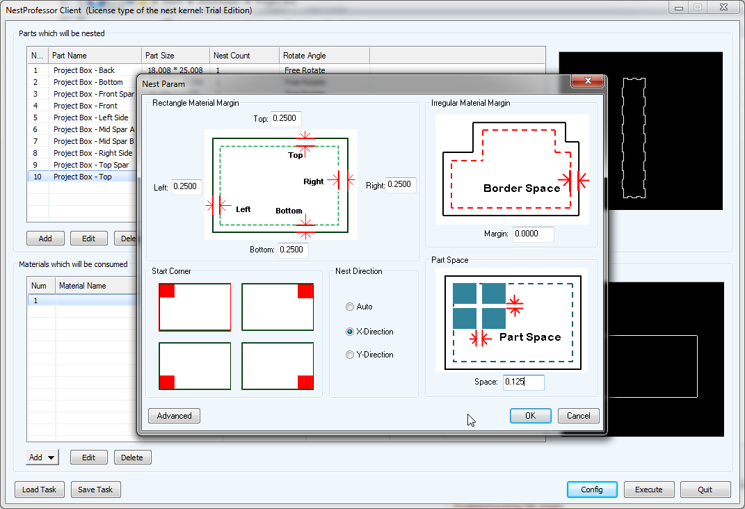
You now have a bunch of DXFs for each individual part. Now we need to lay these out efficiently so that we can make the most of the material when we cut. This operation is called "nesting." There's a couple solutions here. The easiest , and first thing to try is to use the Onshape Auto Layout feature, but this only gives good results if all of your parts are reasonably close to rectangular. To use Auto Layout while avoiding CADing duplicates of parts (which is bad practice), do not apply laser joints in the part studios. Create an assembly, insert and pattern all of your parts, and then from the toolbar click "Create Part Studio in Context" (as of this writing, the right-most icon). In this new part studio, first create a transform feature, choose "copy in place" as the operation type, and select all your parts. Now add any laser joint feature(s), kerf compensation feature(s), and then finally auto layout feature(s) to arrange the parts for cutting. You will then need to create a 1:1 Drawing, with views cropped to each cut sheet, and export as PDF/DXF. These PDFs will need to be processed in your laser cutter software to reduce line width so the parts are cut and not rastered. For more complex shapes, you'll need to use an actual nesting solution. SVGnest is a free, open-source solution, but only accepts SVG files. To use this, you'd need to use something to convert your DXF to SVG and then nest. Deepnest is downloadable, and takes DXF input, but costs $5 per saved output (you can mess around with it without exporting as much as you want). NestLeader has a free trial version and takes DXF input, so that's what I've been using.
|
   |
Arul Suresh, 1 Dec 2017