category: SummerBlogs
Gaby's 2020 Summer Blog
Week 1
June 25-26: I joined the BDML slack, and in the new exploratory hand channel, Mark, Rachel, Michael and I are discussing ideas for a two-finger "lobster claw" gripper. There will be one rigid finger and one longer soft finger (actuated by a tendon) that can explore the environment with tactile sensors. I also started doing tutorials on OnShape, which BDML uses for collaborative CAD projects. So far, it seems pretty similar to Solidworks, but it also has its nuances that I'll need some more practice with.
Week 2
June 29-July 3: This week has involved reading a lot of past research/papers about soft robotics, finger design, active surfaces, etc. As a team, we discussed the possibility of a snap-on-snap-off digit finger (one would be super soft, while the other is semi-soft, with several rigid members). We're also currently debating whether a linear slider design or linkage design will be better for compactness and range purposes. On my own, I've been doing some sketching of different soft finger shapes and overall hand designs. I also "met" with Rachel this week, and she was super helpful in showing me some key differences between Onshape and Solidworks, especially in terms of workflow. A main distinction is that Onshape has part studios as well as assemblies, so I've learned that part studios are for designing several parts that depend on each other's geometries and positions, and parts can only move in relation to each other in assemblies. Also, Onshape has a great organizational tool to keep track of the history of your parts (you can create versions, make new branches, go back to previous iterations, etc), so that will be very helpful in designing collaboratively.
Week 3
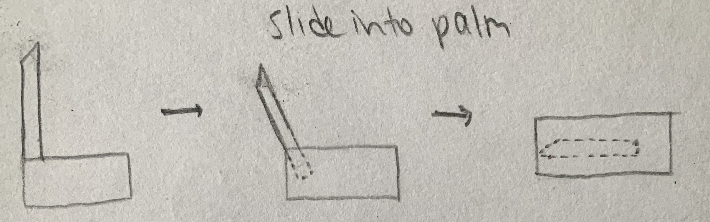
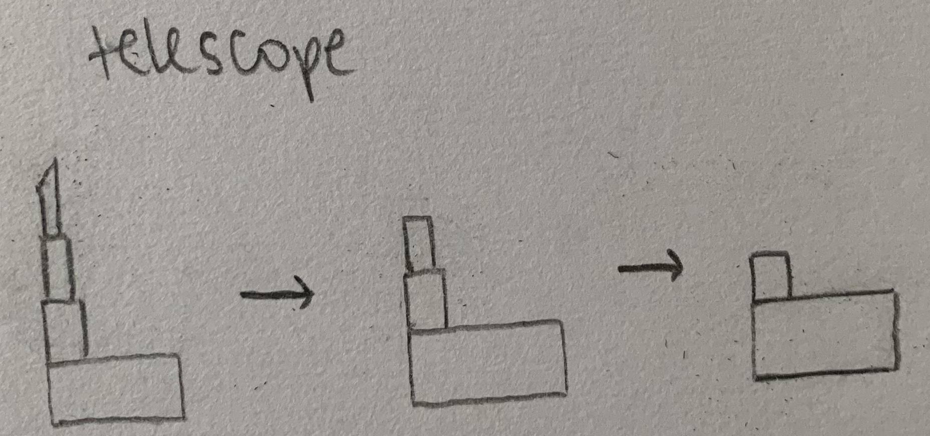
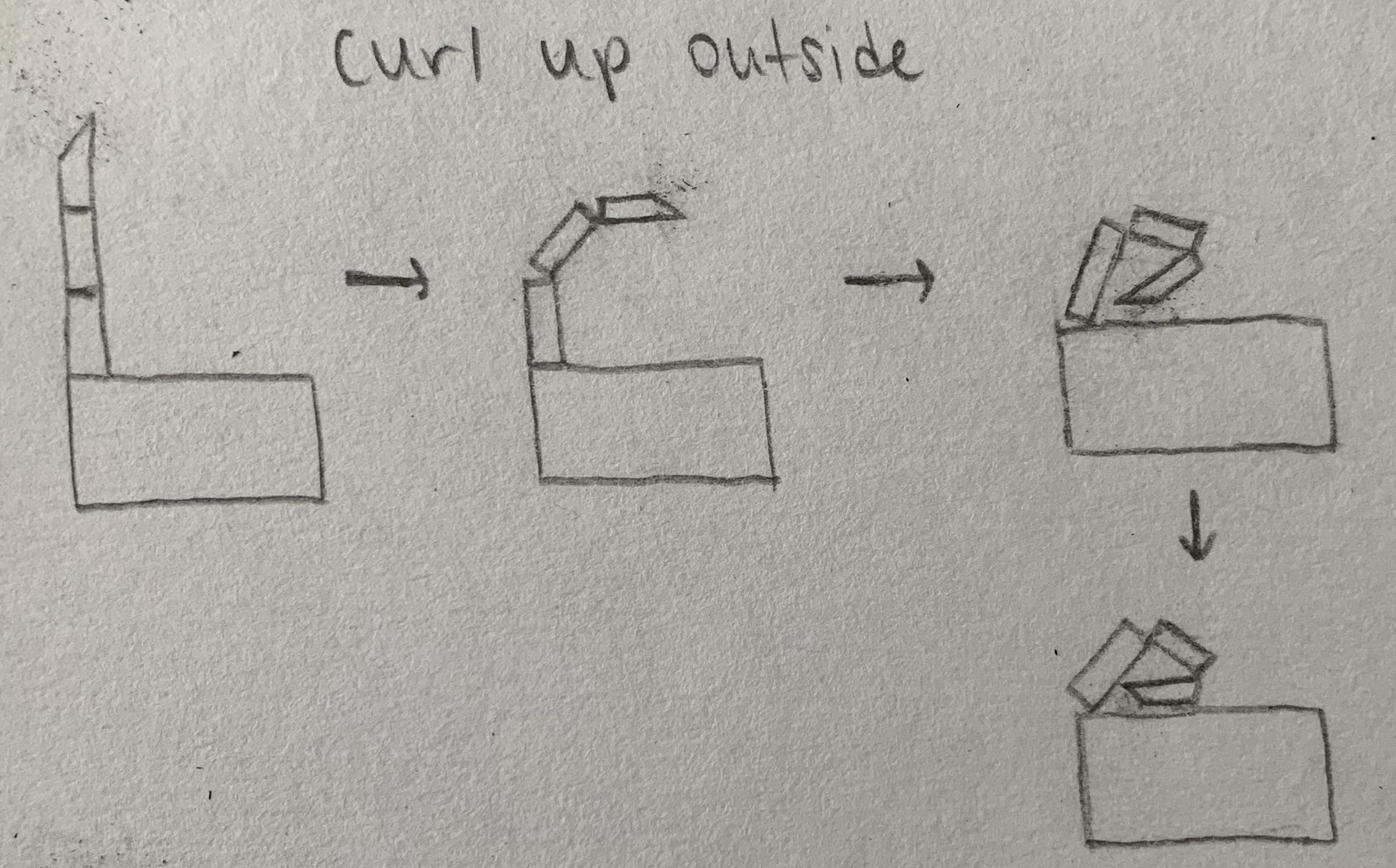
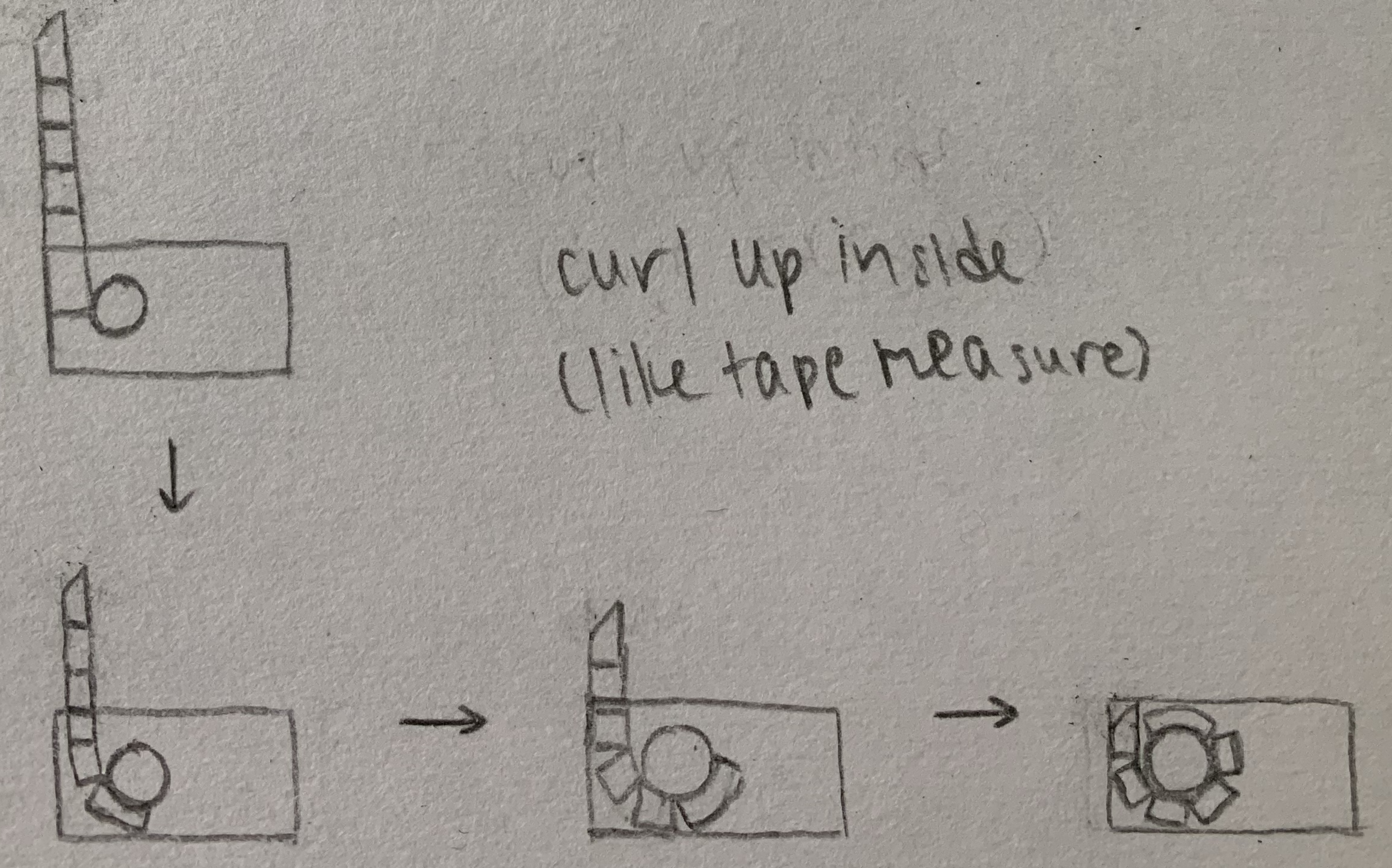
July 6-7: My supplies are here! Now I can start prototyping with foam core, cardboard, dowels, rubber bands, bowden cables, hot glue, and anything else I have around the house. I've used the cardboard to make some linkages, which I'm currently learning more about. Rachel, Michael, and I had a good brainstorming session. We discussed a cool idea of a retractable rigid thumb so that it's not in the way during exploration. This could look similar to a tape measure mechanism, so the thumb can retract and roll up into the palm of the hand. Other options include telescoping or folding/interlacing with the index finger. Shown below are my sketches for these different options.
July 8-10: After a lot of discussion and brainstorming in the last couple of weeks, it's time to start trying out some of our ideas. It seems like for the parallel jaw motion, a linear slider is best, especially if we want the option of switching out the index finger. For the wrapping/enveloping motion, we'll explore options like tendons, linkages, and direct/quasi-direct drive. I've been testing out different linkages on OnShape to see what link lengths give us the desired positions for grasping our determined smallest and largest objects. I also made a prototype that's based off of Michael's Onshape design. It's made of mostly foam core and involves a linear slider motion and a two-jointed index finger. It will be helpful to explore a fridge or cabinet in my house to gain insight on the general feel of the gripper, factors that weren't considered, and any adjustments that need to be made.

Michael's preliminary hand in Onshape
Week 4
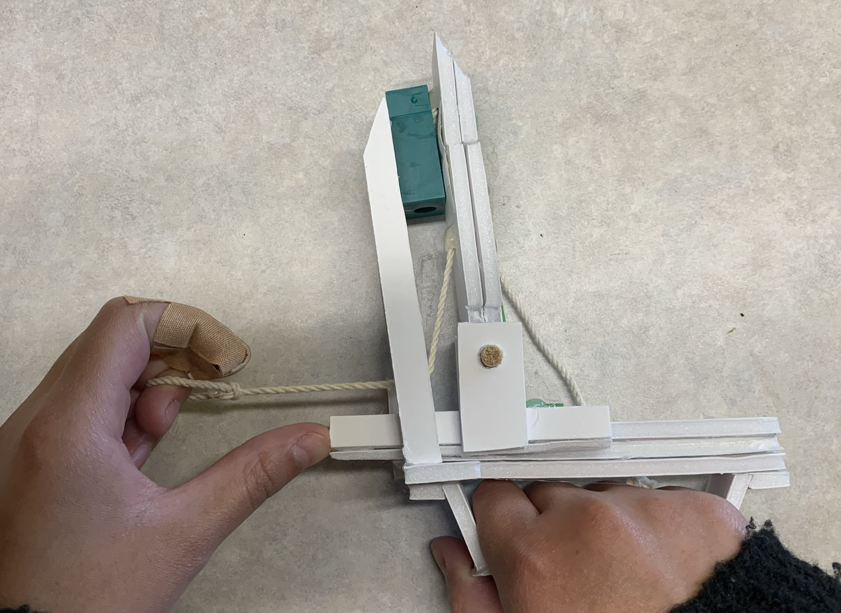
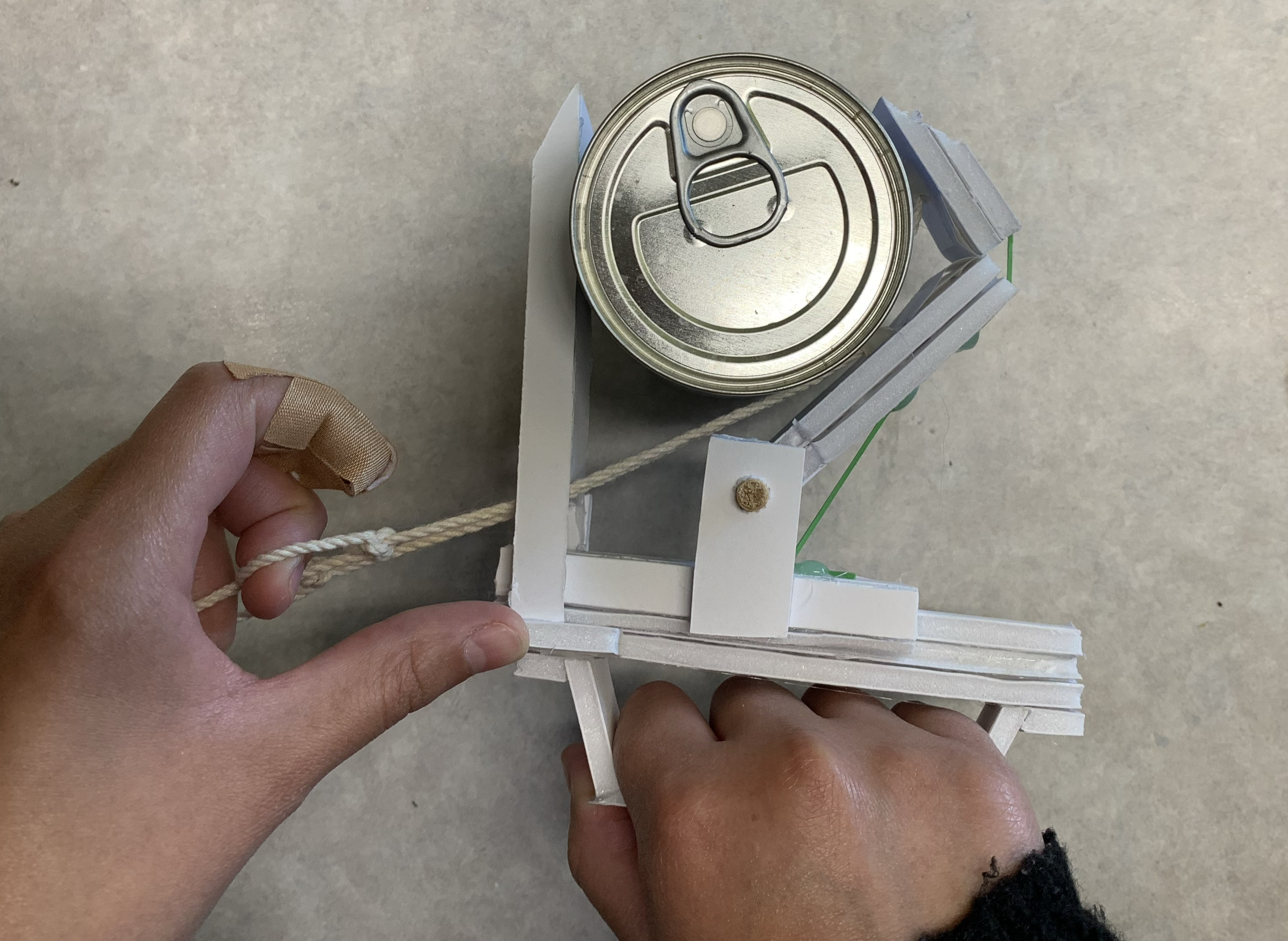
July 13-15: I've improved my prototype to make it more realistic and reliable. I added rubber bands to the backs of the proximal and distal links to simulate the behavior of torsional springs, I made a sturdier handle, and I attached two tendons to actuate the two links. The gripper can achieve the desired grasping positions for variously-sized objects, so it seems pretty promising! After meeting with Rachel and Michael, there are definitely some questions we'll raise to others in the lab meeting on Wednesday. We mainly need to figure how we want to explore an environment with the hand, i.e. determine in which directions we need a soft touch. This will directly impact which joints need to be really backdrivable and which parts need to have low inertia/stiffness. A good next step for the team will be to do some simulation in Gazebo. My next steps include analyzing forces on my 4-bar linkage design to determine if it will "unravel" when gripping objects, updating my prototype to have a single tendon (string) that actuates both links, and drafting a similar tendon-driven finger in Onshape.
Video of prototype pick up small object
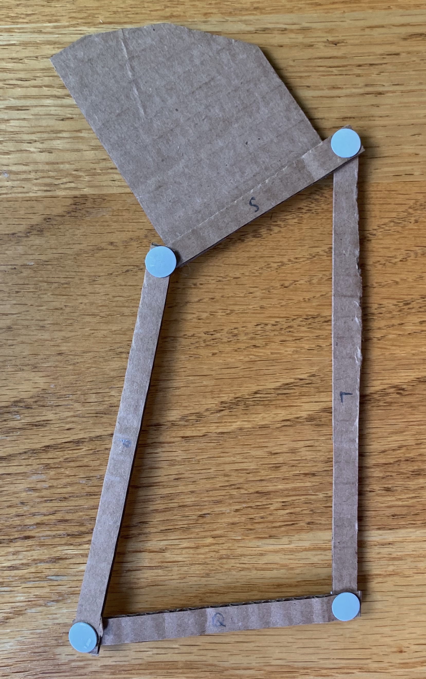
July 16-17: When considering the way the 4-bar linkage will behave in an actual gripping situation, I figured it would be helpful to just make a quick cardboard prototype and apply forces to it myself. As Mark and I expected, when the linkage is in a pinch-grasping orientation (the left side pointing straight up), any normal force applied by the object to the linkage, either on the proximal or distal link, will cause it to bend at the distal joint. This is clearly an issue. If we want to continue with a 4-bar linkage design, we will likely need a sort of brake to keep it rigid while the object is in grasp. This definitely adds to the complexity of the hand, and we're trying to keep it as simple as possible. Also, regarding the movement required to actually grasp an object, it makes sense to have the parallel jaw motion set the desired wrist size, and then use the enveloping mechanism to envelop the object with the index finger. By playing around with the prototype and the Onshape linkage, it seems like the nature of the linkage does not allow for a good "wrap-around" motion, so the hand will have to simultaneously adjust its wrist size and amount of wrapping in order to get into the proper position. This also adds to the complexity of the design, so these factors are ones to keep in mind when moving forward.
Week 5
July 20-23: I've updated my prototype again, this time using a single tendon that actuates both the proximal and distal links (this is what would be employed in a higher fidelity prototype). In Onshape, I'm currently designing a tendon-driven index finger that's similar to this prototype, so it's been interesting and helpful going back and forth between the two to compare details and figure out how to model different aspects digitally and physically. In Onshape, I'm creating a through hole throughout the finger, along with filleted edges and dowel pins to ensure smooth tendon movement. For the prototype, I used string and cut-up pieces of a straw to create the tendon's path on the finger. In either case, it's important to note that the farther the tendon is from the point of flexure, the less force that is required to bend the link (think about the relationship between distance and torque). In Onshape, I'm making "dog bones" that are typically made out of urethane and act as the flexure joints for the finger. In my physical prototype, I used rubber bands to act as both the flexure joints and an antagonistic tendon that pulls the finger back to its original position.
July 24: Mark sent an email to me and a few people involved with the ME102 curriculum about how my prototype is a good example of how you can use simple materials to enhance a design. Giving ME102 students a kit of materials could be a great way to learn and prototype remotely this year. Mark thought it'd be helpful for me to include a bill of materials for my prototype, so here it is: foam core, hot glue, wooden dowel rods, string, straws, rubber bands, scissors, ruler, exacto knife
Week 6
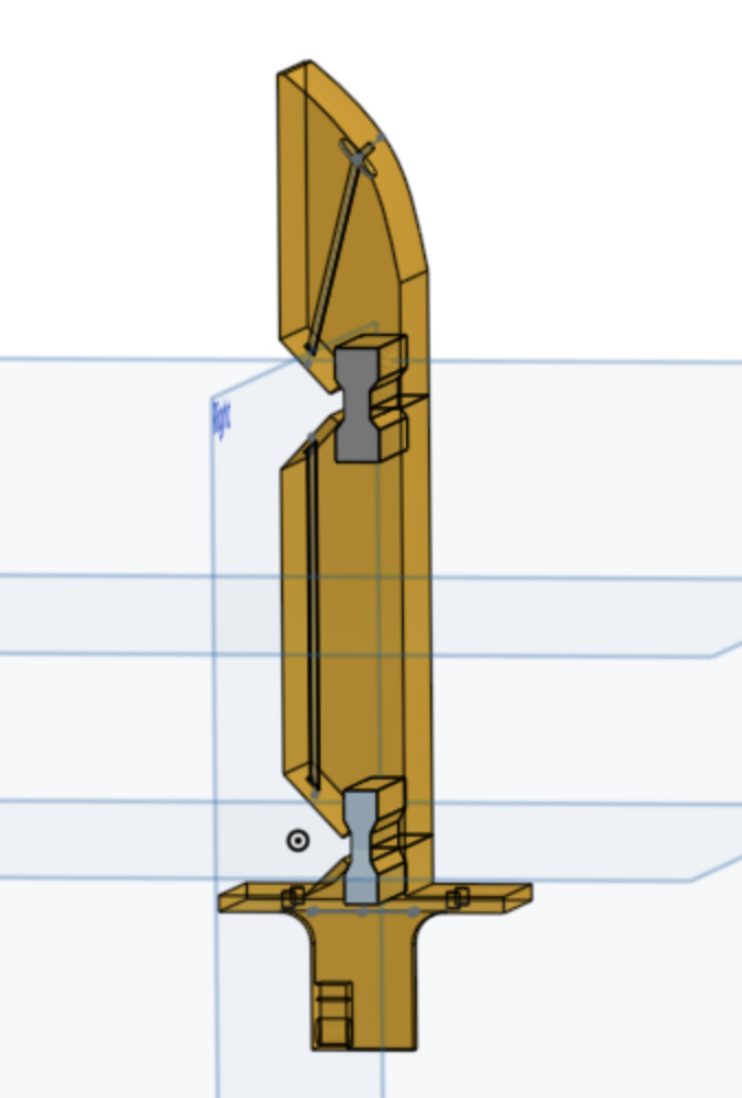
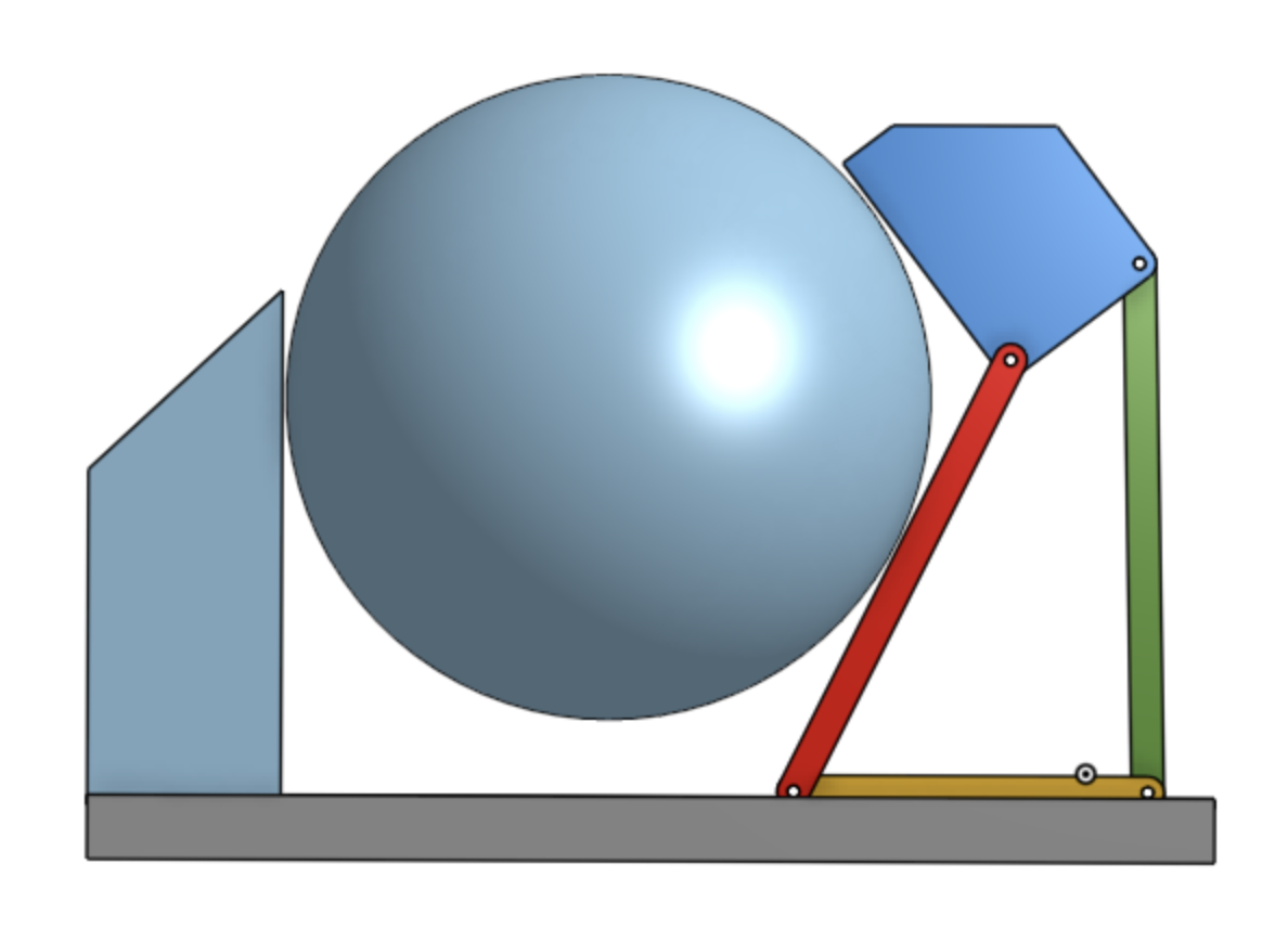
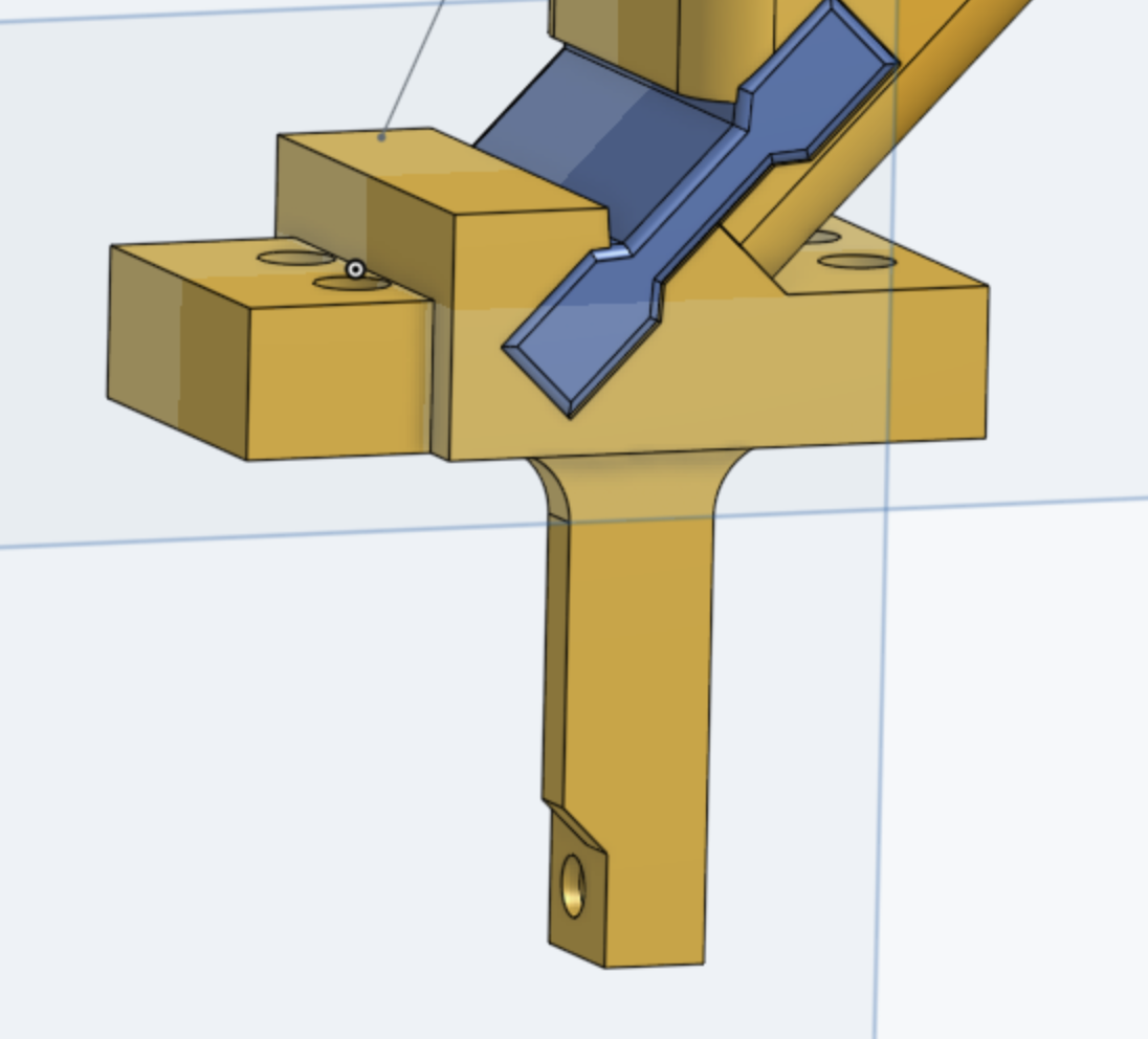
July 27-28: During the TRI meeting last week, we discussed a few different things regarding a tendon-driven index finger design. We talked about the idea of one vs multiple tendons to control the proximal and distal links. While multiple tendons may allow for more varied movement of the finger, it adds complexity that we don't necessarily want, and it would likely lead to a bulkier wrist (which we want to avoid) with several motors. So, sticking with the one-tendon idea, another question is if the tendon needed to be routed around a dowel pin, or if it could be threaded straight through the proximal link. The image on the right shows the latter option. The concern for a straight through route is that the material between the tendon and the edge of the finger may be too thin. Moving the tendon closer to the center of the finger would remedy this issue, but it would also decrease the torque, therefore requiring more force to bend the joint. As long as we avoid having excessive friction (by adding a steel dowel pin and fillets on the tendon exit holes), having a single, routed tendon seems like a good design choice for moving forward with 3D printing a prototype.
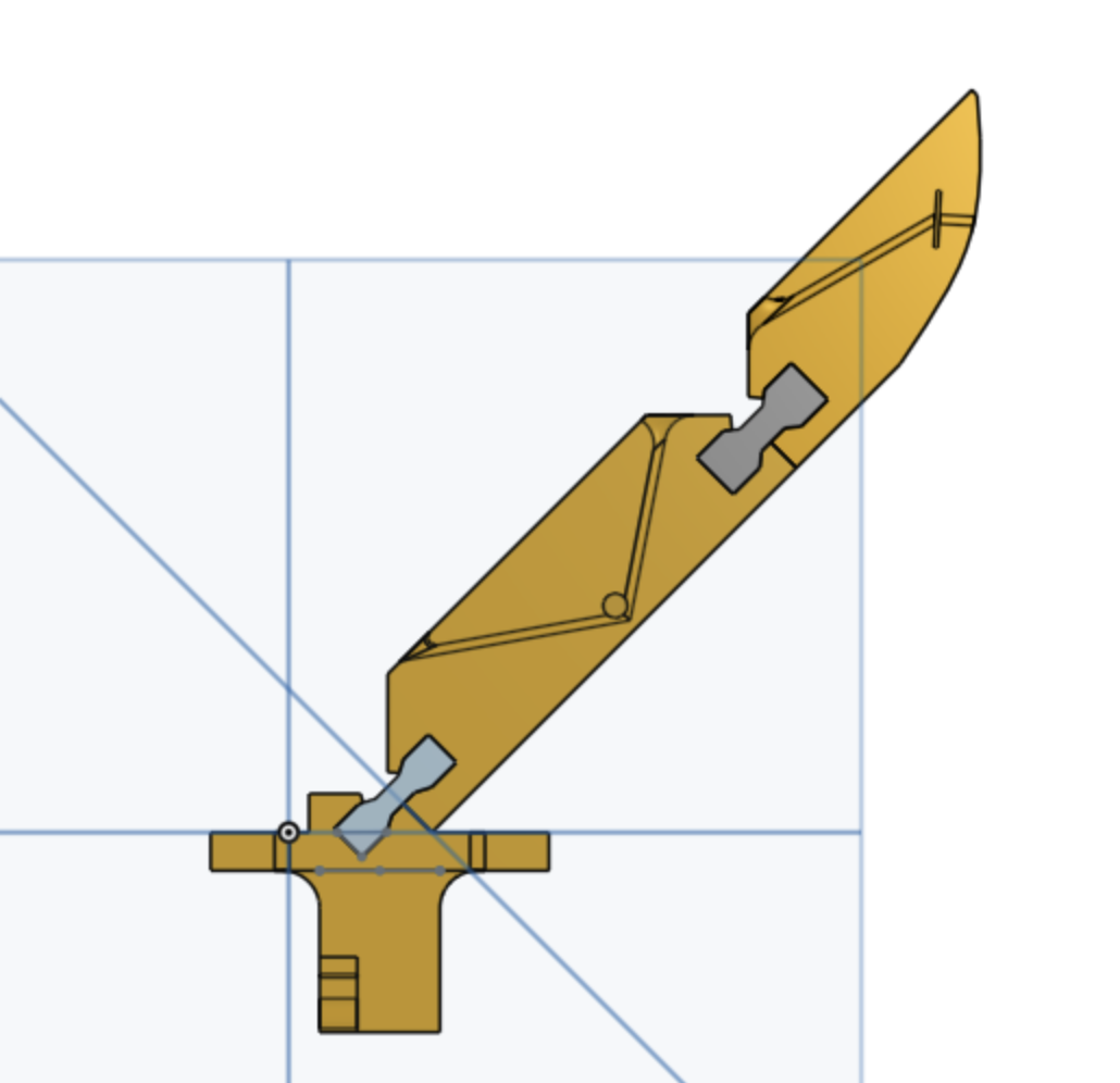
July 29: While working on the finger in Onshape, I realized that with its current resting position and its hard stops, it cannot bend backwards at all. Previously, our team decided that ideally, the hand would have a small wrist and be able to grasp larger objects with the wrap-around reach of the index finger. So, I realized I should change the CAD in order to fulfill these design goals. It was fortunately a very simple fix, where I just rotated the finger 45 degrees backwards and kept the base the same. After all, the proximal joint rotates 90 degrees, and there's really no reason for the proximal link to fold until it's parallel with the linear rail. Ironically, I'd made this adjustment to my physical prototype, which you can see in the pictures above, but I'd forgotten to do the same thing in CAD until now.
July 30-31: My top priority right now is to make some final changes to the CAD design I've been working on to get it ready to be 3D printed. Talking to Michael and Rachel was really helpful in figuring out what needs to be adjusted before printing. These changes include adding fillets to all the edges, making the tendon routing holes larger, adding a counterbore hole in the distal link, and making sure all the finger base dimensions match what Michael has. I will also need to put the finger in assembly and use revolute mates to see how the links actually move. This will show me if the edges line up well as the finger closes, or if parts collide with one another, in which case I'll need to adjust the lengths of the dog bones.
Week 7
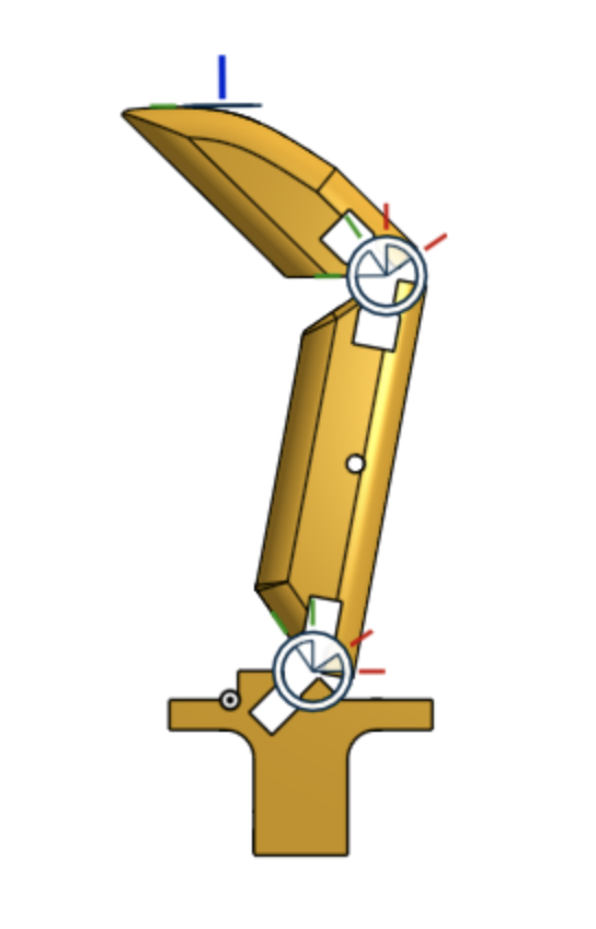
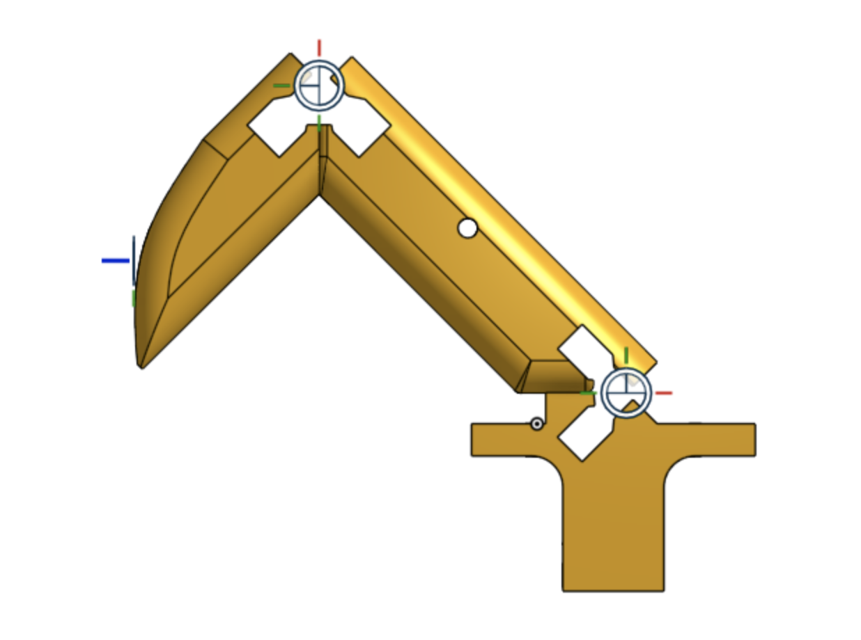
August 3-4: I've made a lot of the necessary changes listed above. The biggest thing I did was put the finger in an assembly to see how the parts would actually move and interact with each other. Initially, the dog bones were too short, which caused the links to collide instead of bending the full 90 degrees that the joint should allow. So, I changed the dimensions of the dog bones (they're both 1 inch long now), and the links fold up perfectly now, with the edges lined up correctly.
I also adjusted the base of the finger so all the features and dimensions matched up with Michael's. The index finger he's been working on is a simple rigid finger, similar to the thumb, so he can keep testing the linear sliding DOF. It's important for my tendon-driven finger to have the same base as his so we can easily remove/attach the fingers and experiment with different designs. I made sure to keep two sets of holes in the base so it can attach to two carriages on the linear slider, counteracting the moment caused by the force of the object being grasped.
August 5-6: A big discussion topic this week has been where to put the motor for driving the tendon. One idea is to mount the motor on the side of the finger base and have a pulley on top of the base to reroute the tendon to the motor. A similar design would be to have the motor on top of the base, so it slides into the rigid finger's gap. Difficulties with these concepts include making sure the tendon lines up perfectly with the pulley, the weight of the motor potentially increasing the finger's inertia, and ensuring the motor doesn't interfere with the motion of the finger. Inserting the Polulu motor bracket into the hand assembly showed us that it's larger than expected. Working a lot in Onshape can skew how you view the size of parts, so it's helpful to remind yourself of the actual dimensions. Rachel called it "CAD goggles", which I think is a great way to describe it. Another thought brought up was if having two tendons, side by side, would be a better option for actuating the finger. Having equal forces on the left and right would avoid out-of-plane moments that having a motor on the side could cause. According to Mark, though, this adds complexity with a design that is not absolutely necessary.
For all of these reasons, we've decided to go with a bowden cable to connect the tendon to the motor. This allows us to put the motor on the hand base (which has plenty of room), so it doesn't interfere at all with the rail or either finger. Having the sheath also eliminates the issue of slack in the cable getting in the way. Bowden cables can actually be pretty flexible too, so that helps as well.
August 7: Michael has started planning for the paper we will write about our gripper design. He's written up a sort of "mock paper", which I think is a really cool and useful way to make an outline. Organizing the different sections and drawing up plots of what you expect/want your data to look like is a great foundation to start a paper on, and it's definitely a strategy I'll keep in mind for the future. He has also created a timeline for what needs to happen up until the paper is due, from hardware to experiments to writing. Rachel and I will look everything over and give Michael our feedback on the main ideas and details of the paper.
Week 8
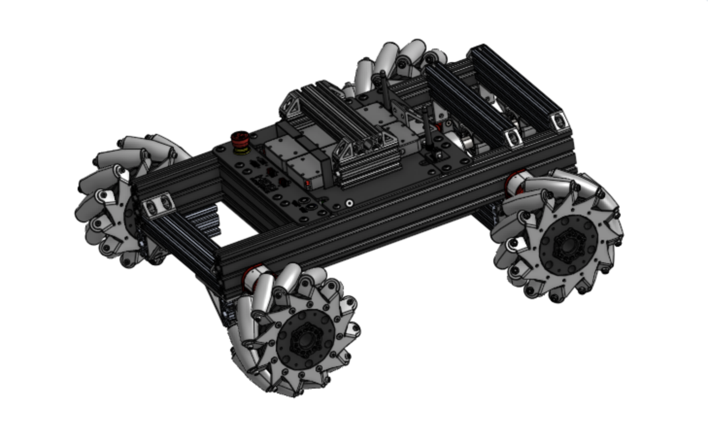
Solidworks assembly for mobile platform
August 10-11: Michael is about to order a mobile platform to mount a robotic arm, and there are a ton of Solidworks files for the platform. Since I have a newer version of Solidworks, I'm helping him out with opening files, determining which parts are where, and figuring out what to order from McMaster. So far, the files are pretty confusing, since all of the names are product codes instead of descriptions. There are also subassemblies within the overall assembly, making it difficult to determine how many of each component part there are. We'll keep working, though, and hopefully can figure out everything we need to get for
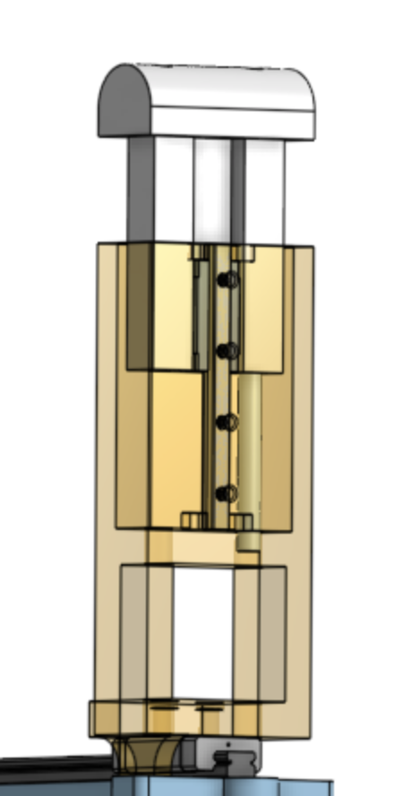
Telescoping finger design
the mobile platform.
Rachel has been working on an index finger with a passively telescoping fingertip, which is really cool! It would allow for "aggressive" exploration into a cluttered environment without knocking over objects. The design has the fingertip sliding into the rest of the finger with a small linear rail and two springs.
Another big focus of this week has been going over the paper plans. One of the main ideas of the paper is that being able to touch and not displace an object makes it easier to determine its state faster since we do not propagate uncertainty in the environment. Additionally, a question that was brought up was if we should go into actually exploring cluttered spaces, or if it's better to leave that for future work given all that the paper is already discussing. To me, this question, along with the main idea of not propagating uncertainty, brought up an idea of having an experiment where the gripper explores a "semi-cluttered environment". This type of environment would have objects that are spread apart far enough where the hand can find, touch, and gain information about each object, and reach the target object without having to move any of the other objects out of the way. This would show the advantage of quickly interacting with objects without propagating uncertainty. This sort of experiment would also be a good stepping stone to future work with a more dense cluttered environment, where you would want to purposefully move objects out of the way to get to the desired object.
August 12-14: I was finally able to figure out the Solidworks files for the mobile platform, so that was great. I turned one of the biggest subassemblies and the overall assembly each into a separate zip file, and I was able to upload them into Onshape and share them with the team. Michael used the files to figure out some key dimensions and discuss those during his call with Flexiv, where he and Mark negotiated to gain use of one of their arms. So, I'm glad I was able to help him prepare for that.
The last thing I needed to do to get the tendon-driven finger ready to print was make sure the dimensions for the dog bones are realistic in giving us the right amount of stiffness. I went about this by looking at the Ocean One hand and looking at the ratios of different dimensions each dog bone had (i.e. thickness:length). The good thing is that many dog bones can be cast at once on a big sheet, so we can test different dimensions and urethane types to see what works stiffness-wise.
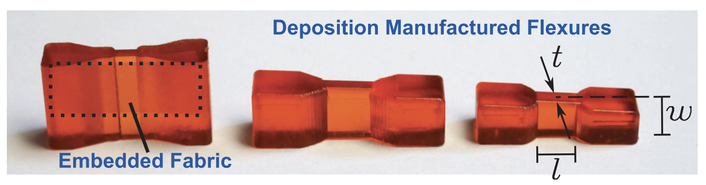
Ocean One hand dog bones
With the ICRA RA-L deadline a couple of months away, we are really shifting our focus to doing everything necessary to get the paper ready. This includes figuring out what experiments will best support the main ideas we want to express. I'll be thinking about this over the weekend in preparation for a brainstorming session we're going to have with Sam and Arul.
Week 9
August 17: The brainstorming session was very helpful in figuring out the details of what experiments we should do for the paper. We mainly discussed the first two experiments, which will show how the gripper can quickly touch objects in a safe way (doesn't knock over or break them) that doesn't propagate uncertainty. The first one involves making contact with a rigid peg that has force torque sensor to determine the forces that would be applied to objects when they are found in a cluttered space. Collecting this force data for different approach speeds will show the benefit of having a hand that applies lower forces on the objects it runs into. The second one involves making contact with objects and measuring their displacement on different surfaces. This will exhibit the gripper's effectiveness in propagating minimal uncertainty for more efficient exploration and acquisition. Michael and Rachel will do this experiment on common household surfaces, like wood and tile (countertops), as well as plastic (fridge shelves) and cloth. I definitely wish I could be on campus to help with all these experiments, but it is what it is and I'll keep doing whatever I can to help remotely.
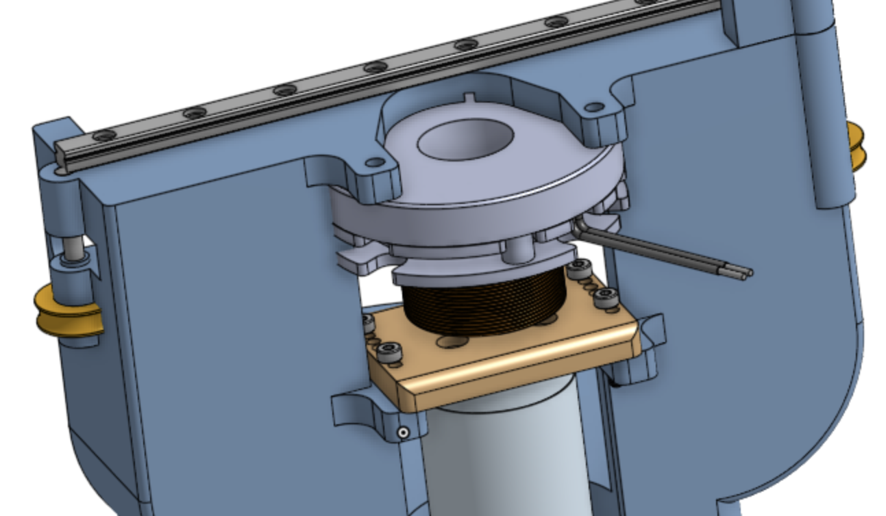
August 18-20: Since the Pololu motor ended up having cogging issues, we're now using an RE 25 motor to drive the parallel grip. When overdriven, this motor can apply about 14 N of force. While we don't need this much force for most of the experiments, it is necessary for lifting and holding various objects, which we want to show. Therefore, it's important to add a clutch so that we can overdrive the motor for a moment and then lock the hand in place. I have been adding a clutch mount to the CAD part studios/assemblies so that the clutch can be mounted upside-down, between the top of the palm and the capstan. The BXR CAD model is very similar to the clutch Michael has, except that the hollowed core of the BXR is a square instead of a hexagon. Something I noticed with the model is that the clutch sticks out slightly in front of the linear rail. So, depending on where the capstan is (there's an adaptive base so its position can be changed), the mobile finger may need to stick out farther from the palm's edge in order to avoid hitting the clutch.
August 21: We're presenting at the lab meeting next week, so we need to think about what we want to focus on in our presentation. We've done a lot since the brainstorming meeting back in July, so it'll be great to explain the progress we've made, as well as interesting to hear the feedback from other lab members.