Links: ME112Notes, ME112WebResources,FinalProjectMaterials
Manufacturing Tips
At the drill press...
On this page... (hide)
- 1. Gears and gear mounting
- 2. Bearings
- 3. Joints
- 3.1 Structural joints
- 3.2 Linkage joints
- 4. Cutting wood
- 5. Reducing weight
- March 1: Brought some extra tools into the ME112 lab.
- See also: FinalProjectMaterials
1. Gears and gear mounting
The general problem is to make gears mated to a round metal shaft with
- good concentricity (so that the gear pitch circle is not eccentric)
- good perpendicularity to the shaft axis
- a strong connection that can transmit torque between the shaft and gear
1.1 Commercial Gears
McMaster Carr has a reasonable selection of gears and shafts. The plastic ones are not expensive (search for plastic gears). Jameco Robotics Store does too under Chassis and Mechanical Hardware.
Commercial gears often have a hub on one side and a set screw hole. If they do, then it's a relatively easy matter of boring out the center hole to the right size. It's best to fixture the gear in such a way that it doesn't move around. Buy the gear with an undersize standard bore and drill it out to suit your shaft.
At final assembly, if you file a bit of a flat on the shaft where the set screw goes, it will take more torque. You can also use Loctite or Superglue if you have problems with set screws coming loose. Don't rely only on glue to attach a gear to a shaft.
If the gear has no hub then achieving a high torque connection to the shaft may be harder. Use the same "boss" or shaft collar idea as for the Lego gears. Or make your boss by drilling a hole in a cylindrical piece of plastic or masonite. You can also make coupling collars which easily attach to a commercial gear (axially) and connect via a set screw or other radial feature to the shaft.
See note below about Lego gears for fixturing ideas.
1.2 Mounting Lego Gears on Shafts
The Lego gears are of relatively high quality with close tolerances. They can be bored out to fit larger shafts, but this is tricky because (i) the center hole in the gear is not round but is shaped for a spline, which causes a drill bit to "wander" as it starts to cut and (ii) the sides of the gear (or the front and back depending on your terminology) are not flat which means that you can't just put the gear against a flat surface and expect good planarity.
So what is the solution? The ideal solution would be to have a large collet or other fixture that would (i) support the gear from below around the edge of the gear (which is flat) and (ii) center it precisely and (iii) be stiff enough to hold it rigidly so that it doesn't shift when you start trying to drill it. The collet would ideally be lined with a material soft enough to prevent damaging the gear.
Apparently there is a collet and a "block" at PRL that work well for holding gears while drilling or reaming them. Ask a shop TA for help if you are attempting this modification!
The next best solution might be to wrap the outer edge (the teeth) of the gear in a layer of electrical tape to protect them and then put the gear in a large chuck like a lathe chuck. This would at least assure concentricity.
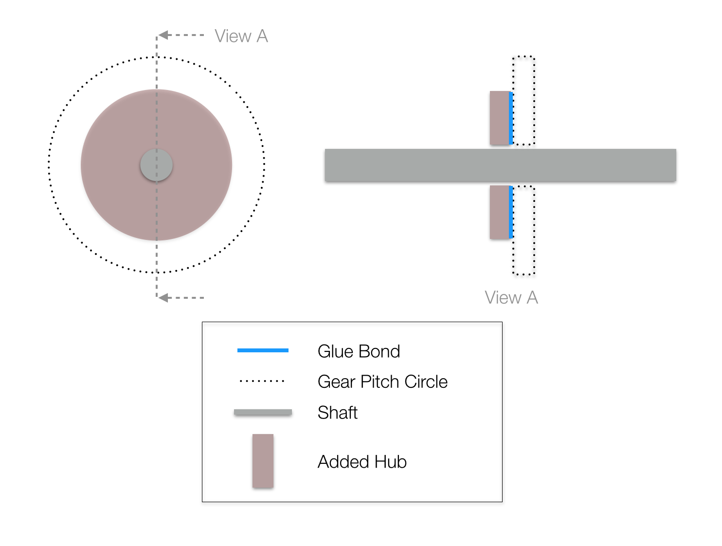
The problem of perpendicularity can be reduced if the gear is butted against a "boss" or "hub" on the shaft. The boss is just a round piece of material with a concentric and perpendicular center hole that fits on the shaft (shown in light brown in the image below). The boss is glued to the gear (blue line below) to provide a larger area for transmitting torque.
Feb 2014 Another reasonable idea would be to lasercut a "Lego gear shaft adapter" adapting from the DIY Lego Gear tutorial.
Another possibility is to use a commercial shaft collar to help transmit torque + also enforce perpendicularity. One such item is sold by Pololu here. I can put a couple of sample shaft collers in MERL 133 (1/4 bore) for people to experiment with -mrc
1.3 Motor/gear connections
Often the motor shaft has a small diameter. What if your pinion gear already has too large a hole? The only good solution in this case is to make a spacer whose inner diameter matches the motor shaft diameter and whose outer diameter matches the gear. (You can always make the hole in the gear a bit larger to match the O.D. of the spacer.) Ideally this spacer would have an end flange. Ideally it would be made of something like brass which is wonderful for machining small parts with good tolerances. Then you could Loctite or superglue the assembly together. I should try to make a picture of this...
If you can find a tiny vise or clamp or chuck or collet to hold the motor shaft rigidly, you can file a small flat on the motor shaft. This will help with torque transmission. It's important not to accidentally put loads on the motor bearings when doing this; you'll ruin them.
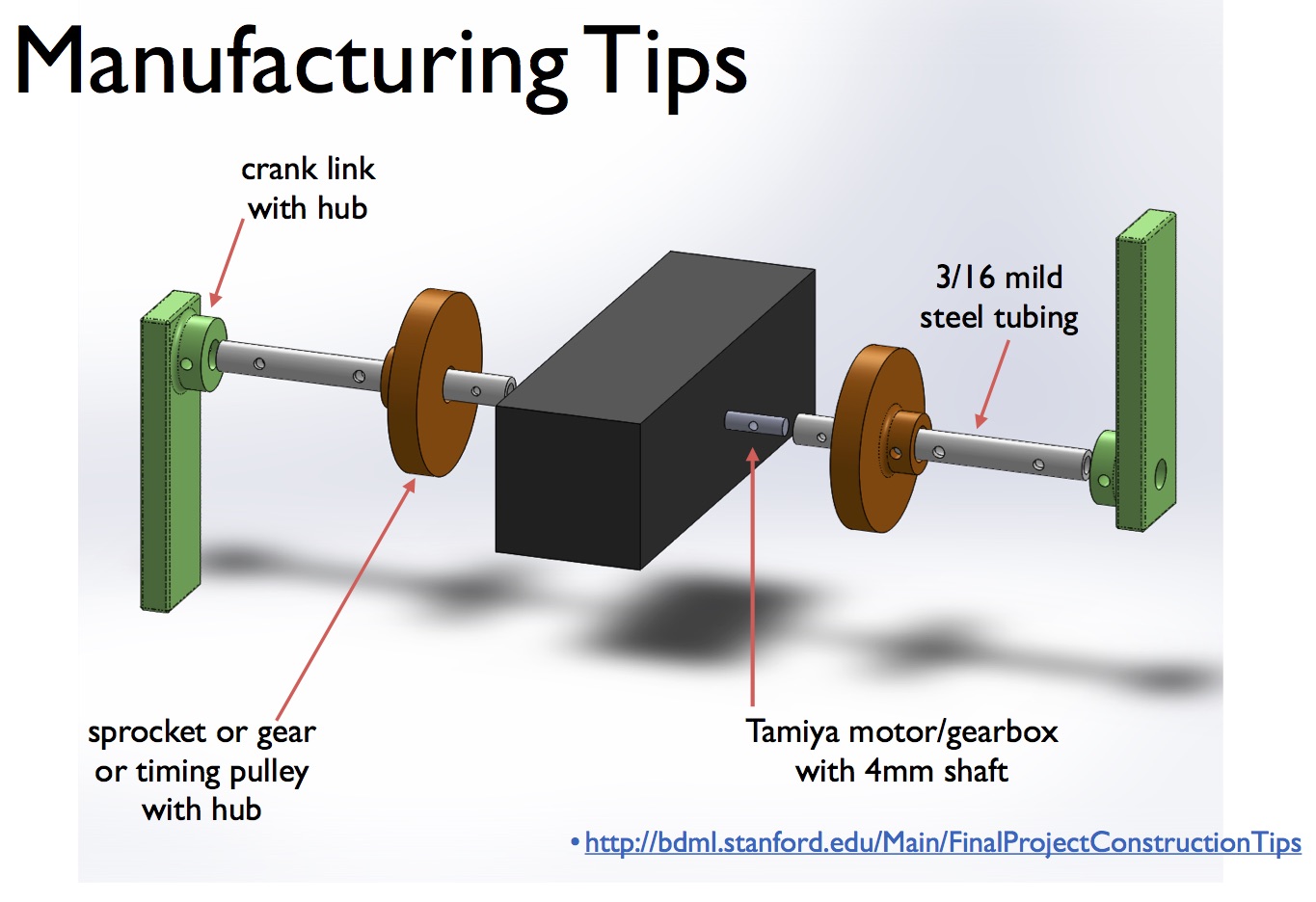
(click to enlarge) The ideal tube is 4mm ID, 6mmOD
mild steel, available at McMaster Carr
Conversely, if the motor shaft is about the same diameter as the shaft you want to connect it to, but it's too short, then you want a shaft coupling. There are commercial ones you can buy (drill out the inside bore on each end to match the motor and other shaft). A cheap solution, if torques are not too high (which they often aren't right at the motor) is to use some nylon or metal tubing. If you have trouble getting a press fit connection to hold the torque without slipping, you can put a pin through the tube and shaft as shown in figure. Tamiya motors usually have a 4mm diameter shaft, so 4mm ID tubing is ideal.
1.4 Shaft/gear Connections
Another way to connect a gear to a shaft is to use something like a cotter pin or spring pin. In order to do this you only need to drill through the gear flange and not worry about tapping for a set screw.
If the shaft is case-hardened, as it often is if steel (a reason not to use steel), you will need to nick it with a grinder or file to get through the hard shell. Then you can drill it. Be sure to use a tapping oil or some kind of lubricant!
2. Bearings
- Plain "sleeve" or "flanged" (sleeve with a flange or washer attached to one end so it can take some thrust load) are simplest. You want them to be a bit loose on the shaft. If you press them into a mounting hole that is slightly undersized they will collapse inward just a bit, giving you a snug but still low-friction fit.
- Ball bearings are bit fussier. They should be pressed gently into a mounting hole. When you press them, be careful to only press against the outer rim (not the inner one, which would produce large axial loads on the balls and likely ruin the bearing). Although it's not great practice in general, for a limited-life prototype like the Duck-bots, the outer rims can be glued in place. (Be very careful not to get any glue inside the bearing!). Be careful as bearings may rust if they are made of susceptible materials and are not protected from water exposure.
- The fancier and more time-consuming approach is to make retaining ring grooves and use retaining rings or "C clips"
3. Joints
3.1 Structural joints
Feb 2014: For 2014, wood parts are only going to work for above-water components ("inside the boat"). Even then, you'll want to use the water-resistant wood glue. Below water, you'll need to use plastic, aluminum, etc. Note that water-resistant wood glue is much easier to clean up than Gorilla glue or epoxy.
3.2 Linkage joints
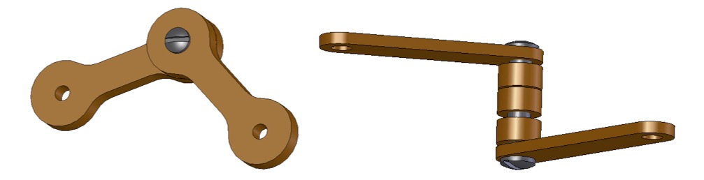
Joint at left is sturdy and won't wobble; joint at right will, unless you glue the "washers" to one side
For minimum slop and wobble, the "pin" should be rigidly attached to one of the two links. For example, if you use the screw posts (see MaterialsAndSupplies), you can press fit the female part into one link and, ideally, secure it with a bit of glue. (It will help if you roughen the underside of the flange using sandpaper or a file.) Then place a plastic washer over the post and place the second link over it. The hole in the second link should give a snug, but free-rotating, fit. Finally put another washer on top of the second link and fasten the cap screw in place. If you have trouble with the screw loosening in use, you can use Loctite, superglue or (a bit cheezy but it works) nick the threads slightly with a file before screwing in.
4. Cutting wood
A good thing about Masonite is that while it cuts beautifully on the Lasercamms, you don't really need to use a laser cutter. For small pieces, it's faster to use a coping saw and vise. For making holes a drill press or even a hand drill works just fine. (Drill press is better if you need to ensure the hole is perpendicular to the face.)
24 Feb: We will provide a drill press and scroll saw for you to use from Professor Cutkosky's lab. Please treat them well, and don't lose the drill bits we provide.
- Wear glasses!
- Vacuum, when done
- Put tools away
5. Reducing weight
You want to minimize the weight of your robot components. Why? Because a beefier linkage results in a heavier robot, which results in larger forces in the linkages and a higher torque needed from the motor. So then you need a bigger (heavier) motor and more batteries. So your robot gets even heavier. A vicious cycle...
Suggestions:
- Use the 1/8 thick Masonite for lightly loaded parts such as links that undergo mostly tension and don't need much torsion or bending stiffness. Thin Masonite can easily be braced by gluing small pieces of wood (or more Masonite) at right angles to it. Think 3D versus 2D.
- Cut holes everywhere. I will bring a couple of big hole saws into MERL 126 that can be used with the drill press. Again, as you take out more material you may need to add a bit of stiffening braces.
- Don't use thicker shafts than you really need. Steel shafts are heavy; aluminum shafts are lighter (and easier to cut).
- Don't use a bigger motor than you need.
For those of you who are using Jameco sprockets, check your chain tension (chain tension * sprocket radius = torque). You are likely to run up against the ~6lbf maximum tension.