On this page... (hide)
1. Introduction
The objective is to create a parametric numerical model that can be used to characterize the quasi static and dynamic behavior of the Annular EAP Diaphragm (Fig 1.) when subjected to out of plane deformations. The annular geometry of the diaphragm helps linearize the viscoelastic response of the diaphragm, resulting in fewer losses due to damping and increasing the bandwidth of the device. The same geometry also creates a catenary like surface profile when subjected to out of plane displacements. Once complete the model could be used as a tool to better understand and design artificial muscles and implement concepts comprising of a collection of such elements (such as stacked concept in Fig 2.)
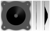
Fig. 1 Schematic for annular diaphragm: (L-R) top view, side view, side view(deformed)
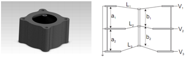
Fig. 2 (L-R) Multi Unit Stack Concept, Cross-section of three units [2]
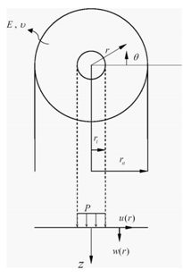
Fig. 3 Geometry and Notation for a center-loaded membrane. The inner portion provides a net vertical force P. The resulting edge-loaded annular membrane ri<r<ra is analyzed. (Yu et.al)
2. Finite Element Model
The model performs a non linear (large deformation) analysis using Ansys. Shell 209 (a 3 noded axisymmetric shell element) was chosen. A simple Hookean model for an incompressible material was used.
3. Comparison with Yu et.al., 2009
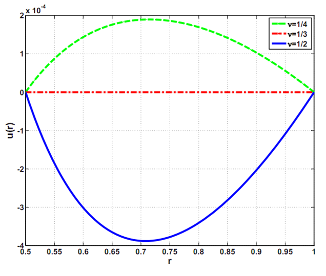
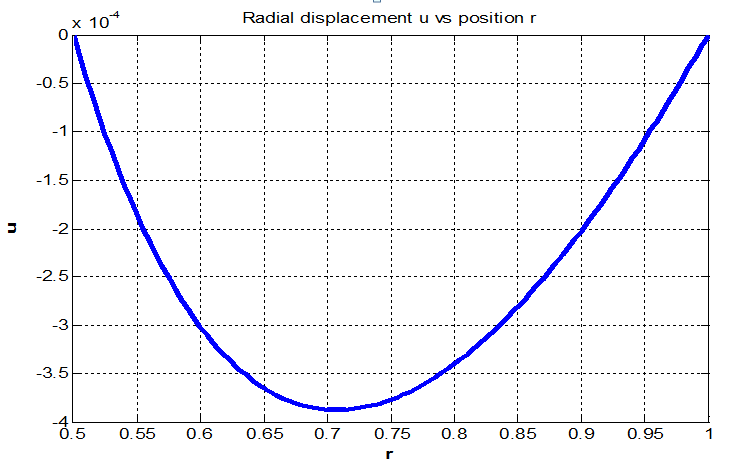
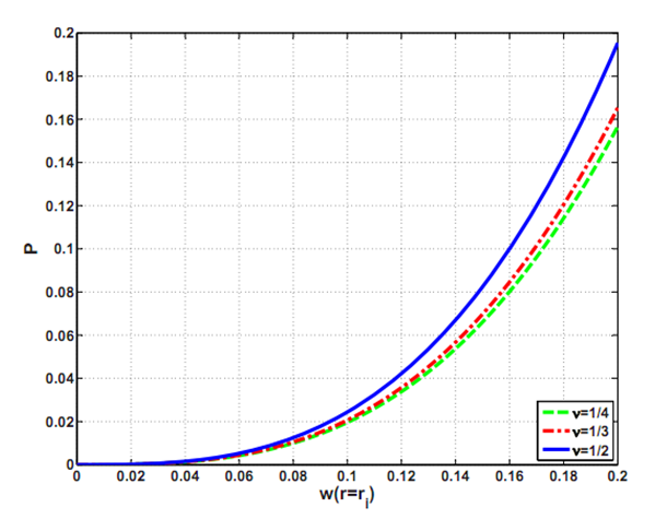
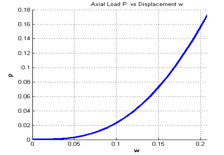
Comparing results with analytical solutions derived by Yu et.al. we found reasonable agreement. The radial displacement matched very closely. The Axial load (Fig. 5) matched for small displacement however we found deviations (within 10%) at large values of displacement. It is interesting to note that the displacement in the radial direction are almost three orders of magnitude less than the displacement in the z direction.
(a)
(b)
Fig. 4 Radial displacement u(r) with prescribed vertical displacement w(ri)= 0.1, w(ra)=u(ri)=u(ra)=0 and ri/ra = 0.5. a)Yu, et.al b)Present study.
(a)
(b)
Fig. 5 Axial force P, applied at the inner boundary versus out of plane displacement at inner boundary w(ri) with prescribed boundary conditions w(ra) = u(ri)= u(ra)= 0 and (ri/ra) = 0.5 a) Yu. et.al b)Present study.
4. Comparison with Experimental Results
The model was modified to match the geometry of an actual annular EAP diaphragm. The objective was to match the quasi static experimental response(Fig. 6) to that obtained from numerical model. A simple Hookean Model was attempted for simplicity. A basic parametric study was conducted to find the value of Young's Modulus to match the Force displacement plot obtained experimentally. As expected from Fig. 6 the Young's modulus increases (observe local slope) as the displacement increases. The same behavior was also observed from Numerical Model. For wi = 0.5e-3 m E=5.5e6 Pa, wi=3.5e-3 m E=19.1e7 Pa. Hyper elastic models are very common for modeling EAPs. To further support the use of hyperelastic models for the given geometry, the value of Equivalent Strain (Analogous to Von Misses Stress) was evaluated at different radii. As seen in Fig. 7 for wi =3.5e-3 m (worse case) strains of up to 12% were observed (in addition to the pre-strain of 400%).
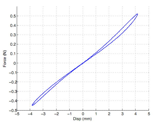
Fig 6. Workloop test on a single diaphragm. Test was conducted at 1Hz with +/- 4mm of displacement and no applied voltage [2]
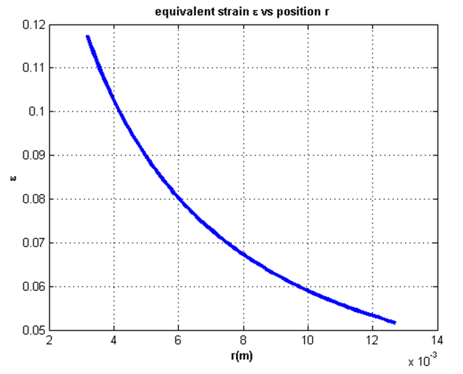
Fig. 7 Equivalent Strains ɛ vs radial position r
5. Next Step
Change to appropriate Material Model
6. References
[1] Design of Dielectric Electroactive Polymers for a Compact and Scalable Variable Stiffness Device, Sanjay Dastoor and Mark Cutkosky
[2] Symmetrical Solutions for Edge Loaded Annular elastic Membrane, Yu & Karr, Journal of Applied Mechanics , 2009