The tactile sensor demonstrator, the sensors on the RobotiQ hand and sensors for the SRI/Meka/Stanford ARM-H hand share a common design. The normal+shear sensor used for adhesion sensing also shares common design elements.
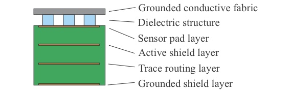
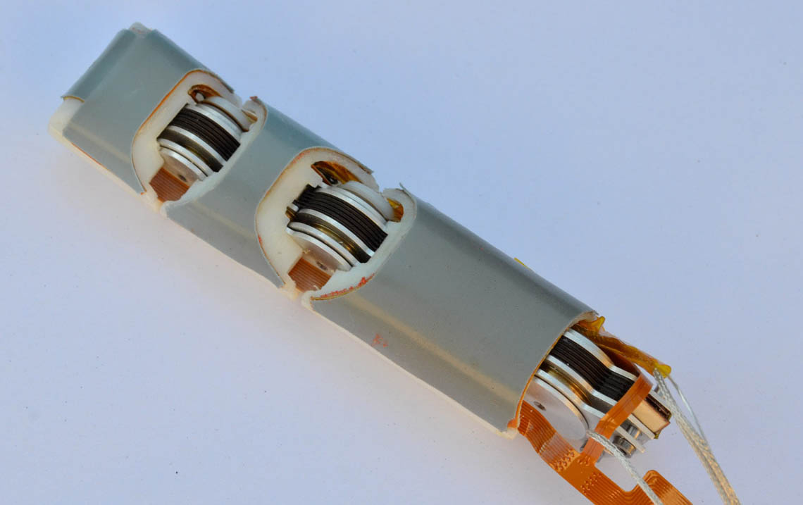
The structure of the tactile sensors is shown at right. A multi-layer rigid or flexible PC board provides grounding and shielding. The upper surface is also grounded, to reduce noise and prevent the sensor from functioning as a proximity sensor. The sensor uses Analog Devices AD7147-1 chips to read the taxels, provide filtering and active shielding and communicate via I^2C bus. Small arrays of n sensors can be sampled at 1200/n Hz. Not shown is an upper layer of protective skin. The skin thickness will vary according to application, and the gripping surface will typically be textured for repeatable sliding performance.
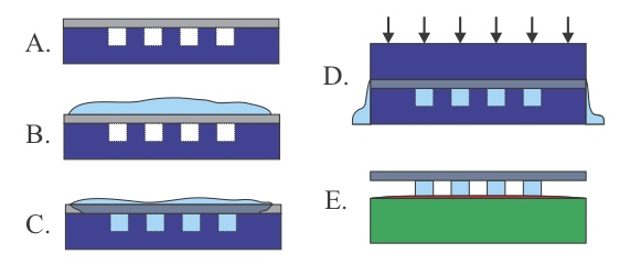
The manufacturing process for the dielectric is shown at right. A conductive mesh fabric is placed atop a mold and silicone rubber is pushed through it into the mold, forming an array of posts. For the demonstrator boards and RobotiQ hand, the post material is a silicone RTV with a durometer of Shore A 25 and modulus of approximately 840 kPa. A top plate is clamped under pressure as the silicone cures. The posts are bonded with a thin layer of silicone adhesive to the upper circuit layer to create a monolithic structure.
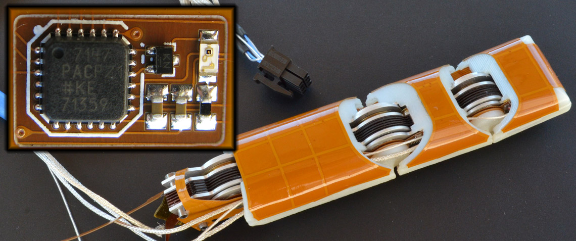
Flexible circuit for finger. Inset (upper left): detail of surface mounted IC
The same basic construction is used with flexible printed circuits for the fingers of the ARM-H hand: