Audrey's Research Blog | Summer 2014
On this page... (hide)
- 1. WEEK ONE
- 2. || June 23
- 3. || June 24
- 4. || June 25
- 5. || June 26
- 6. || June 27 - Lab Retreat
- 7. WEEK TWO
- 8. || June 30
- 9. || July 1
- 10. || July 2
- 11. || July 3
- 12. WEEK THREE
- 13. || July 7
- 14. || July 8
- 15. || July 9
- 16. || July 10 + 11
- 17. WEEK FOUR
- 18. || July 14
- 19. || July 15
- 20. || July 16
- 21. || July 17 + 18
- 22. WEEK FIVE
- 23. || July 21
- 24. || July 22
- 25. || July 23 + 24
- 26. || July 25
- 27. WEEK SIX
- 28. || July 28 + 29
- 29. || July 30
- 30. || July 31
- 31. WEEK SEVEN
- 32. || August 4
- 33. || August 5
- 34. || August 6
- 35. || August 7
- 36. || August 8
- 37. WEEK EIGHT
- 38. || August 11
- 39. || August 12
- 40. || August 13
- 41. || August 14
- 42. || August 15
- 43. WEEK NINE
- 44. || August 18
- 45. || August 19
- 46. || August 20
- 47. || August 21
- 48. || August 22
- 49. WEEK TEN
1. WEEK ONE
2. || June 23
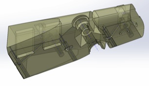
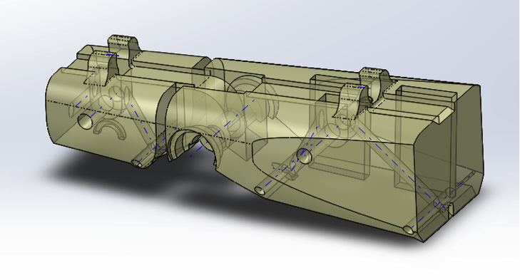
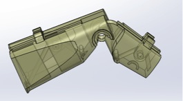
Today was my first day at the BDML! I started working with the Mobile Manipulation team on their underwater robotic hand prototype. After meeting the team and sitting in on a couple of meetings to get a better feel for the project, I was assigned to design and laser cut a cover to contain the parts and wires in the robotic hand prototype in order to prepare for next week's experiments on the prototype.
I used SolidWorks to design the cover - it was my first time using this particular software, so Hannah kindly walked me through the basics. My plan for the design was to offset the top of the cover from the existing prototype parts to leave room for the electronic components inside, and also to have a part that the wires could wind around and go through to plug into the external components. After I had drawn up the parts, Hannah taught me how to use the laser cutter at the TLTL, and we cut out all of the parts required for the cover.
The plan for tomorrow is to put the parts together with the existing prototype, and make any alterations/re-cuts if necessary.
3. || June 24
Had an early morning meeting with Hannah and Alice regarding the layout of the electronics needed for the IR touch sensing on the grasper. It was really interesting to see how IR detection/distance calculation was used in the silicone parts of the fingers in order to create a "touch" sense for the robotic hand. We also discussed the need for op-amp usage to act as a buffer in the detection system, as well as the need to incorporate Hall effect sensors and magnets in the joints of the fingers to be able to deduce the torsion and distance between the segments of the fingers.
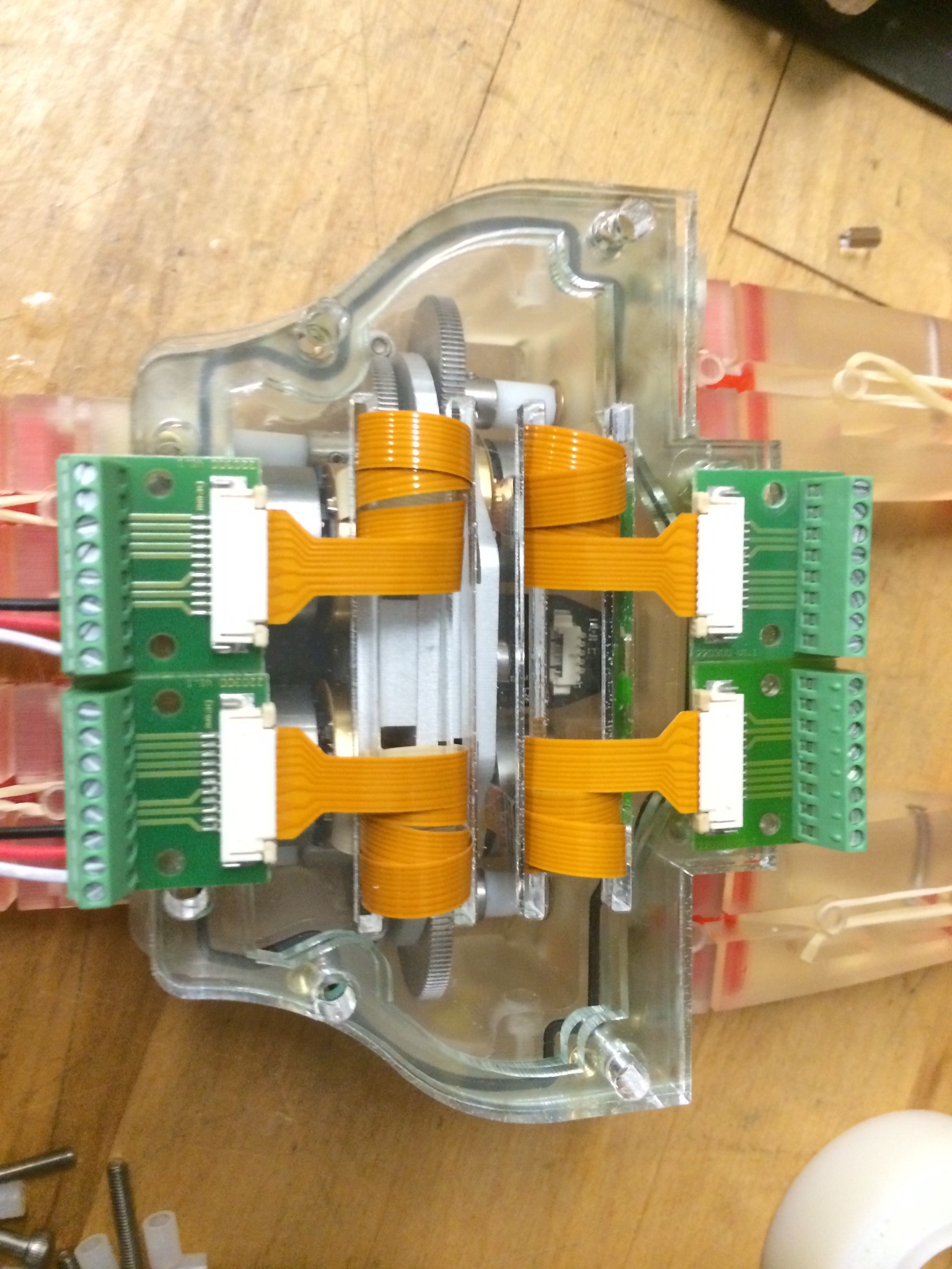
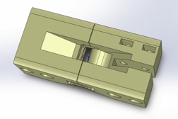
After the meeting, I assembled the parts I made yesterday for the cover of the hand. Took me a while to do this, due to space constraint on the relatively small palm design, and the sizes of bolts and plastic offsets available at the lab, but finally finished it! Below is a picture of one of the inside layers of the cover that organizes the wires:
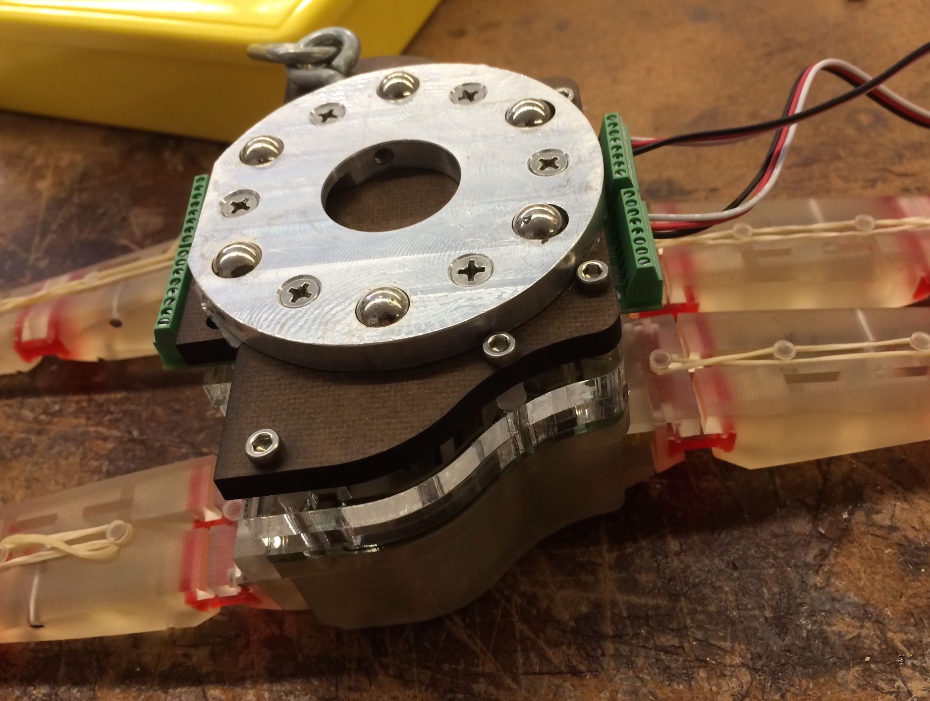
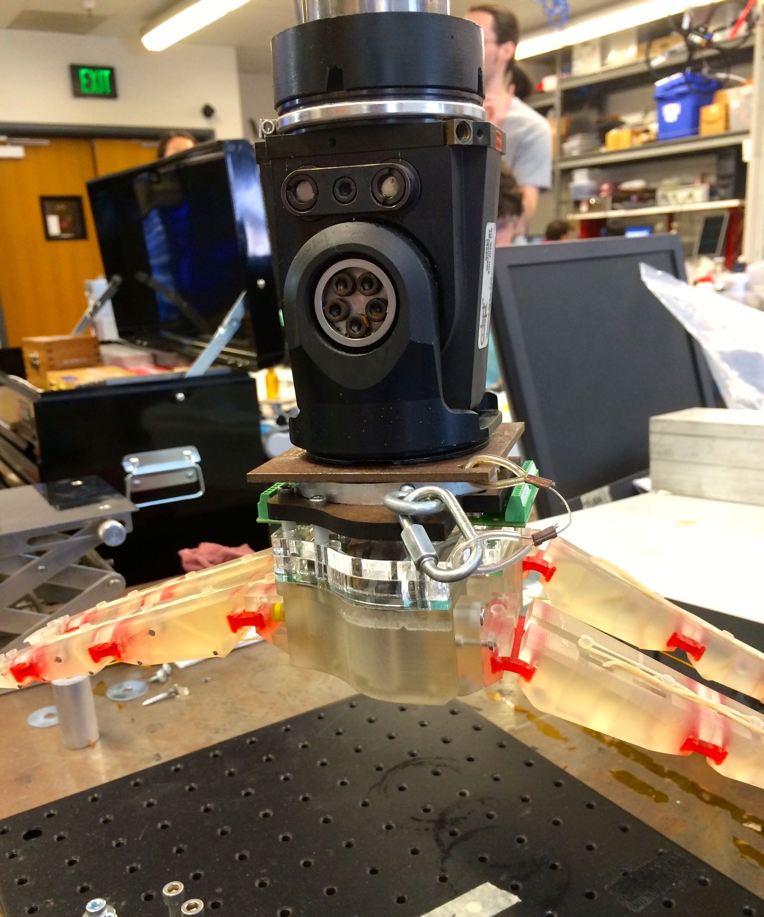
After assembling the inner parts of the cover so that the wires were organized, and there was enough room for the electronic components (both inside and outside), I bolted the top part (with the magnet that attaches on to the robotic arm for testing) onto the grasper prototype. Below are pictures of the fully assembled cover, and the grasper prototype attached to the robotic arm with the new cover.
With this mini-project complete, I started doing some research into Hall effect sensors, particularly on their use in previous robotic hand prototypes. I plan to continue this research tomorrow, concentrating on examining different types of Hall effect sensors and accompanying magnets, as well as looking at how two Hall effect sensors can be incorporated at a finger joint in the prototype to detect torsion.
4. || June 25
I did more research on Hall effect sensors and how to incorporate them into the robotic hand prototype. I tried out different shapes and sizes of magnets to see what effect they would have on the sensors in terms of output voltage ranges. We need the magnets to be strong enough to produce a fairly large change in output voltage of the sensors with small distances, given the relatively minute distances that the segments of the finger will be moving at the joints. However, we are also limited in terms of the space available to embed the magnets in the joints of the robotic fingers. I put together a preliminary circuit with two Hall effect sensors and amplifiers to make the output voltage range more linear - I hope to do more testing using this tomorrow in order to figure out what the most appropriate components will be for the prototype.
Natalie also showed me and a few others how to do silicone casting for IR sensing parts - mixing the different substances to make the silicone, and the procedure to spin the silicone to cast it into a consistently flat piece. Hannah and I will be doing some research into how the different thicknesses of the clear and (opaque) white silicone will affect the IR sensing for the grasper next week.
5. || June 26
In the morning, I attended a meeting regarding IR sensors and the silicone casting/electrical circuits needed to make the parts. Natalie also shared her ideas on flexible force sensing for stroke rehabilitation with me and a few others.
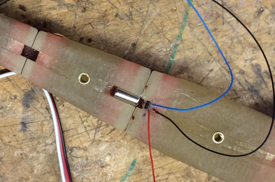
After fixing the preliminary circuit I had built yesterday to test the Hall effect sensors (this required switching out multiple op-amps until I found one that actually worked), I finally managed to amplify the output signal of the sensors to a suitable, more linear range (from 5V to 0V, an improvement from the original max 2.5V of the output signal). The Hall effect sensors I was using for this circuit were already integrated into a larger part with a few other electrical components, which made these sensors too large to fit into a robotic finger for testing. I got an individual sensor and soldered leads onto it, and then fixed it into a cavity in the finger joint. I also drilled a hole into the robotic finger joint and fixed the magnet I had selected yesterday after testing. The picture below shows the set up of the parts in the finger joint - I plan to do more thorough testing of distances and torsion angles vs. output voltage signals next week.
After talking with Mark and Hannah, a rotating magnet setup using the different poles and the changes of the Hall effect sensor output voltages due to this in order to determine distance is also a possibility. After testing the linear setup I have first, I will experiment with other magnet/sensor layouts to determine what the most effective one will be for the robotic grasper.
6. || June 27 - Lab Retreat
Today we went to Sam MacDonald Park for the lab retreat - I spent the day getting to know everyone in the lab better, enjoying BBQ, discussing summer research goals and hiking in the redwood forests.
7. WEEK TWO
8. || June 30
In the morning, I attended the Hand Design meeting to discuss the previous week's progress, and goals for this week. I took readings of the linear Hall effect sensor setup in the robotic finger using different sizes of magnets. After some setbacks with the components used in my experiment (mostly the leads coming snapping off very easily from the tiny Hall effect sensor and needing to solder them back on multiple times), I found that the most linear and reliable output voltage readings were taken with a magnet of 3mm diameter and 9.5mm length. Buddy also showed me and a few others how to use the Adept robotic arm - how to do basic functions like turning the machine on and calibrating it, as well as the programming functions on the attached computer.
Tomorrow I plan on testing torsion readings with two Hall effect sensors, and seeing the accuracy and reliability of readings with the magnet I found useful for the linear readings.
9. || July 1
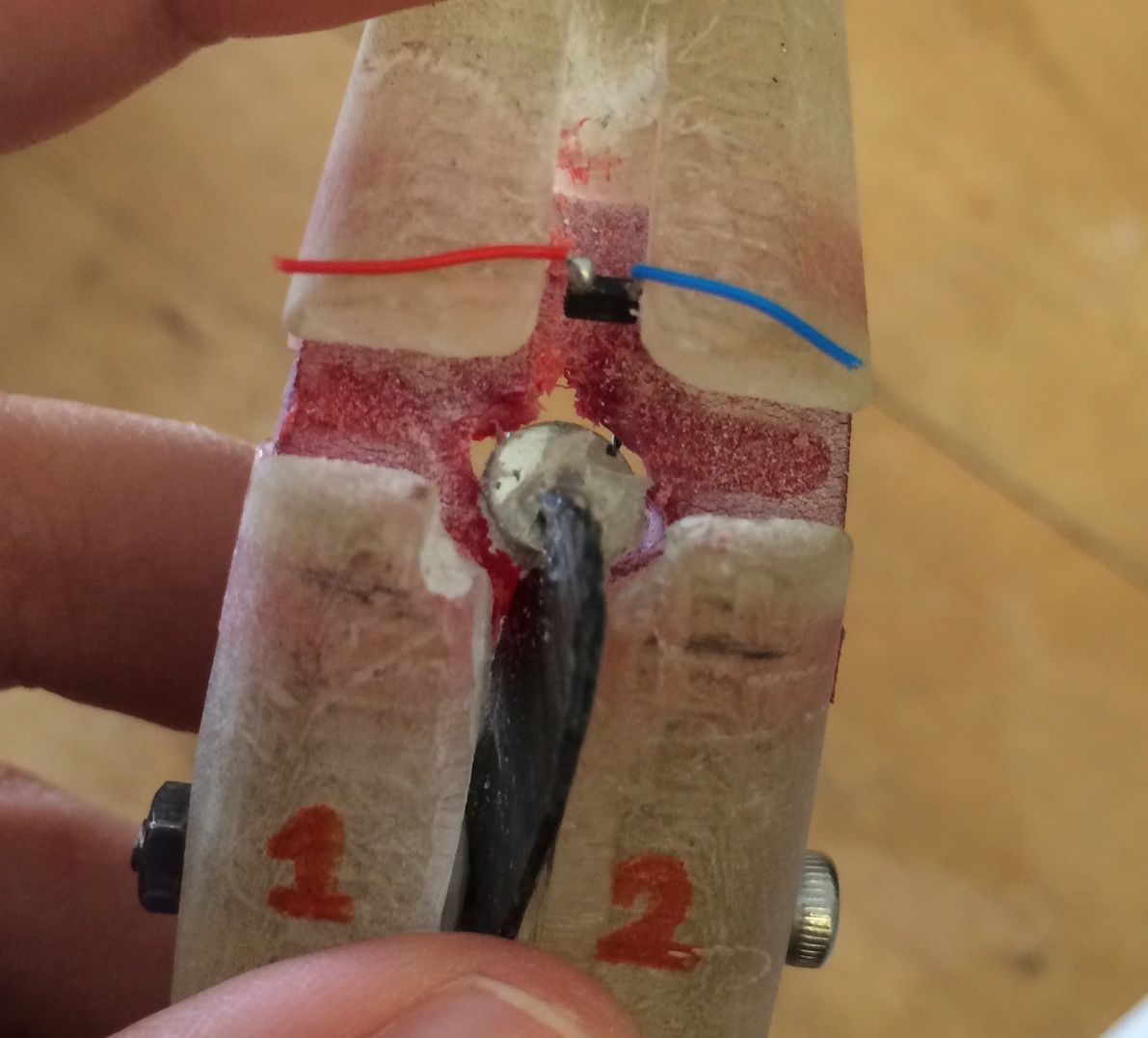
Today I concentrated on making alterations to the robotic finger joint in order to do the torsion experiments. Morgan showed me how to use the Dremel tool, and I used that to shave away an area in the joint so that there was a large enough space to fit two Hall effect sensors across from the magnet. It took me a while to position the Hall effect sensors right in the joint, as the leads I soldered onto the tiny sensors broke off several times (frustratingly sometimes after I had hot glued the sensors in place inside the joint...). When I finally got the sensors set in the right place - centered and across from the magnet, I tested that the sensors were registering the magnet well and giving a good output voltage range. Below is a picture of the setup of the two sensors:
Tomorrow I plan on recording the readings for the torsion experiments, and I will also brainstorm design ideas for incorporating the rotating magnet method for joint angle detection.
10. || July 2
I took the torsion readings today using the linear setup from yesterday - I found that there is a pretty good range of output voltage values for torsion with joint angles from 0-45 degrees, but after that the output voltage range is very small and makes it hard to differentiate between different amounts of torsion.
I then brainstormed design ideas for the rotating magnet/sensor method with Hannah - we worked out that setting the magnet at 45 degrees at the center of rotation of the joint flexure while making the Hall effect sensor circle the magnet was the best setup (as the joint is only bending in one way). We also realized that the best way to incorporate the magnet and sensor in the joint would be to use two flexures, and have the magnet and sensor set in the middle. I then tried a few different shapes and sizes of magnets to find one that would work best in this new setup, and decided on a small, flat donut-shaped magnet. The hole in the middle makes the magnet easier to set in the flexure joint, the flatness of the magnet meant that the change of poles as the sensor rotates around the magnet will be quick and lead to better and more linear readings, and the magnet is quite small and will fit well with the joint size we are working with. I also spent some time drilling various holes into the flexures to thread the donut-shaped magnet in and make room for the long bolts I will use to separate the two flexure layers. In addition, I used the Dremel tool to make grooves in both flexures for the magnet so that it will not move from the 45 degree angle it will be set in.
11. || July 3
I spent the day putting together the prototype for the rotating sensor + magnet tests. After spending some time trying to get the magnet to sit in the groove on top of one of the flexures in the middle area, I decided to try a different method as it was very hard to set the magnet at the right angle to make it equidistant from all positions of the rotating sensor. I used a thin piece of plastic that could be held by the bolt separating the two flexures, and this allowed me to set the magnet at the right angle in a way that was offset from both flexures (see picture below). I did some preliminary testing to make sure the range of output voltages was acceptable (the changing poles makes the output voltage go above and below 2.5 V).
12. WEEK THREE
13. || July 7
Today I finally was able to take the output voltage readings for different joint angles using the rotating sensor around the stationary magnet prototype. I got a very good range of voltage values - particularly for the middle range of angles (~30-60 degrees), which is the most important range for the underwater robotic grasper. We had a Hands meeting at noon to update each other on our progress and come up with goals for this week. I plan to develop the rotating sensor method further to get even more accurate results for joint angle detection - a problem with the current prototype is that the magnet is not exactly at the center of rotation, so the sensor initially starts from a closer distance to the magnet and gets a little further away, which throws off the readings slightly. I also plan to get the system to detect torsion and be able to output reliable voltage values for that as well. I talked with Hannah and we will also be experimenting with silicone casting for her part of the project later this week.
To begin honing the rotating sensor method, I sketched out some ideas and some of the parts and methods that I had experimented with in the past for inspiration. Below are a few of the sketches that I drew today:
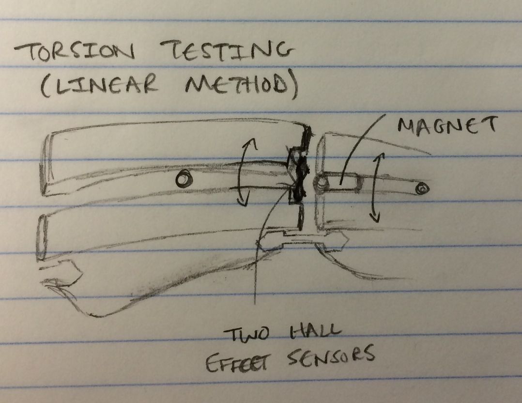
I realized that in many situations with the underwater robotic grasper, the joint angle will be greater than zero when subjected to torsion - using only one Hall effect sensor would make it very difficult, if not impossible, to detect both the joint angle and torsion value accurately as there would only be one output voltage value and there would be numerous combinations of joint angle and torsion that would lead to similar values. Tomorrow, I will brainstorm more ideas to develop the rotating sensor method using two Hall effect sensors.
14. || July 8
I continued brainstorming and developing methods to allow the rotating sensor/magnet method to detect torsion values - also thinking about how to incorporate these systems on the robotic finger prototype. I narrowed it down to two main methods to try out and get readings from: a) to have both sensors in the same plane across from the magnet much like the linear method, except the magnet will be stationary at an angle and the sensors will rotate around the magnet as the joint bends; b) to have one sensor rotating around the magnet to get joint angle readings, and one sensor that directly faces one pole of the magnet with an interference part in between (e.g. a piece of plastic) - as torsion is applied to the joint, the interference part will move out of the way, thus allowing me to take torsion readings.
I started implementing method a) onto the robotic finger prototype - first by drilling a hole through the flexure and 3D printed material, and then using the Dremel tool to clear out the middle part of the finger to leave space for the plastic support and magnet that will be bolted to the finger same as the previous test on July 3 (see picture from that day). Hannah also showed me her new silicone molds, and explained how she plans to make silicone layers for her system.
15. || July 9
I made some progress with the rotating sensor/stationary magnet setup in the robotic finger prototype - I got the magnet to sit stationary at an angle inside the gap I made in the flexure. I encountered some problems in terms of the placement of the sensor, as it was hard to get the sensor to rotate around the magnet without changing its distance from the magnet and thus its output voltage readings - it is difficult to get the setup to rotate at the joint's center of rotation. Below is a picture of the setup in the finger:
I also talked with Dave about possible magnets to use and different sensor/magnet setups. He gave me some great ideas for methods I can try out, as well as some good advice on the different types of magnets. I am currently using a relatively flat, circular magnet, which requires the sensor to rotate a long way around the magnet before there is a significant change in output voltage. Dave suggested that I try putting two small magnets together so that each has an opposite pole facing the same direction - this way, the magnetic field is tighter, and the sensor can move a small amount to get a greater output voltage change. I also decided to go back and test out the linear method, as well as a couple of other methods, using simple setups (i.e. not in a flexure or finger prototype), so I can try out different components and distances easily to find the best setup, and then incorporate it onto the prototype.
16. || July 10 + 11
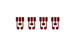
I was having many difficulties with the small leads breaking off of the tiny Hall effect sensors, so Hannah suggested I print out a paper circuit and attach the sensor and wire leads to the circuit. She showed me how to use Eagle to design the circuit, and then to use the special printer with silvered ink to print out the circuit. Below is a picture of the simple circuit we designed:
Hannah then showed me how to use a combination of silver paste and superglue to attach the Hall effect sensor and wire leads to the paper circuit:
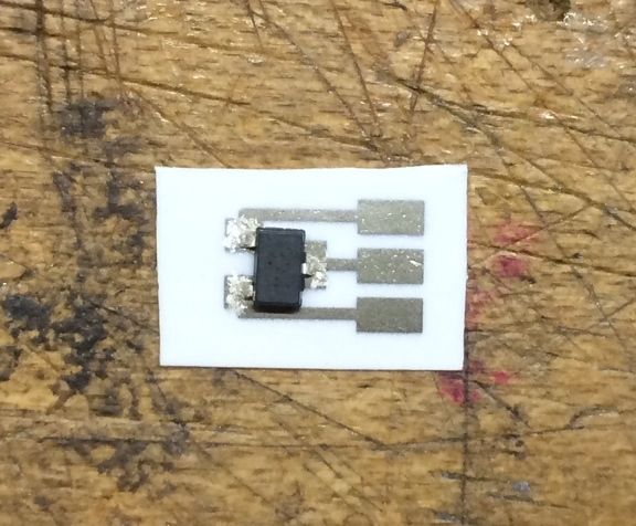
I made sure the connections were solid by checking them under the microscope, as well as using the multimeter's short circuit setting to test that the small legs of the sensor and the end of the wire leads were connected properly. Unfortunately, though the connections tested as sound, after the silver paste dried, the leads were no longer connected very well and eventually even taping down the different components could not ensure a secure connection. Hannah then suggested using protoboards to make the sensor-wire lead connections. I used a hacksaw to cut the protoboard down to the size I needed for the sensor, and then soldered all the components onto it:
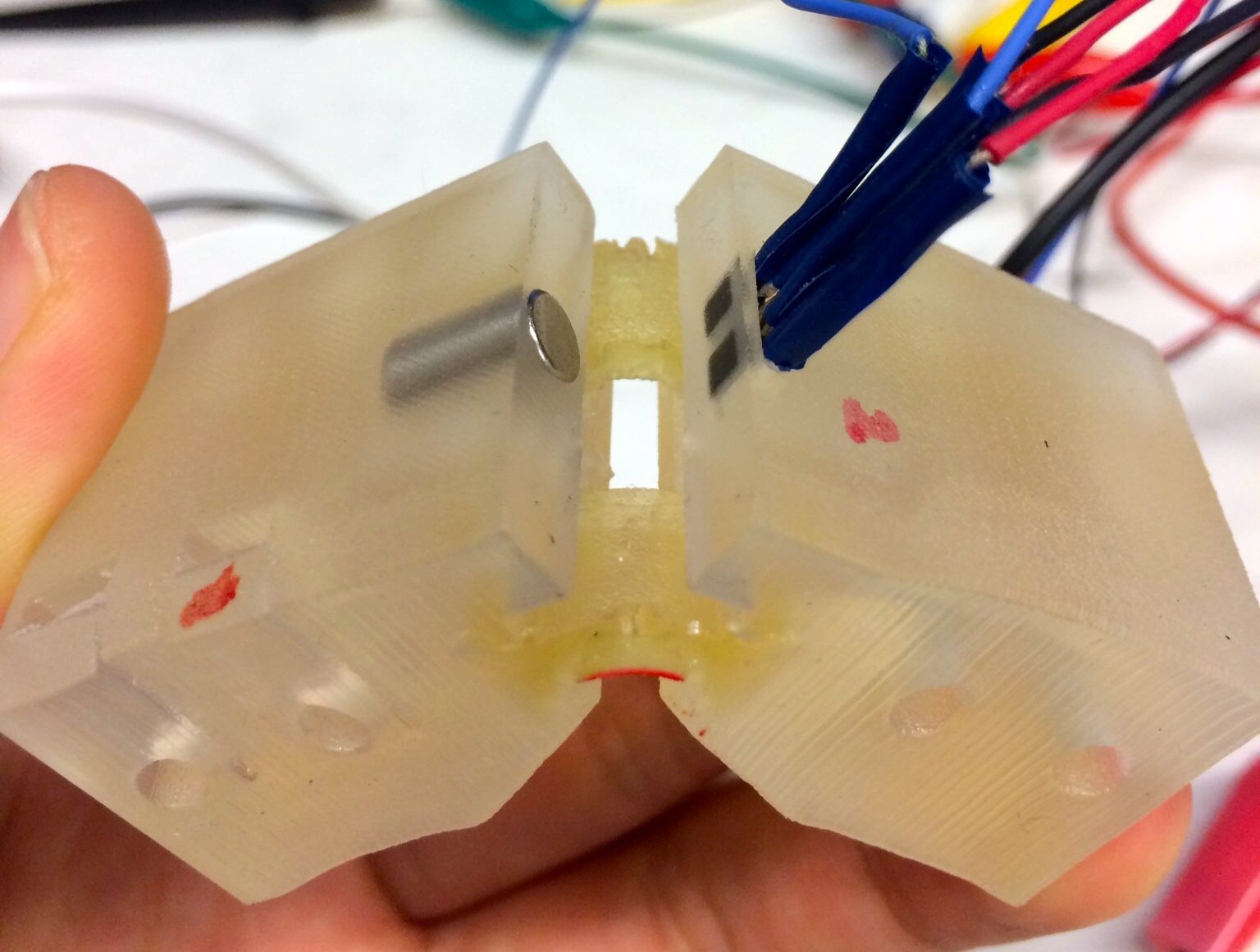
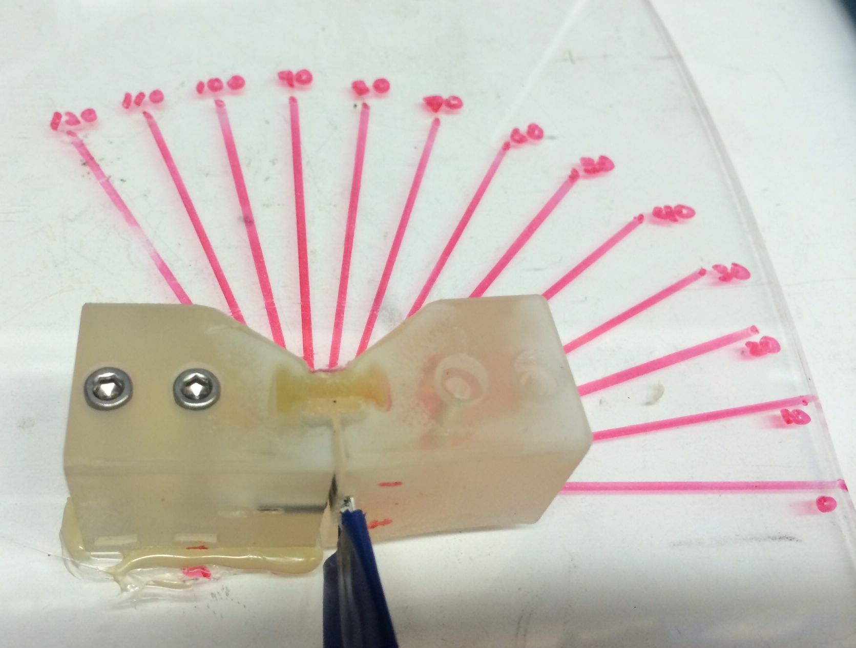
This made for a much better connection, but there were still many issues that occurred as I attempted to attach the two sensors onto the robotic finger joint. Solving these problems consisted of many frustrating hours spent fixing thin wires that broke off inside of the protoboard connections, issues with hot glue, not angling the sensors exactly the same (resulting in different output readings), not positioning the magnet well inside the joint, etc. However, I finally got the setup to work and get a range of output voltage readings that were acceptable. Below are pictures of my final setup to test joint angles and torsion with a rotating sensor/stationary magnet method:
Next week, I will take readings from the prototype, and do any re-evaluations of the setup that are necessary. I hope to make a 3D SolidWorks model of the setup, and start printing out some 3D parts to conduct more accurate tests with.
17. WEEK FOUR
18. || July 14
Today I attended the weekly Hands meeting - Hannah debriefed us on the conference she went to over the weekend, where she was able to talk to a lot of people that are working on projects related to the underwater grasper. Later on, Mark also debriefed us on his trip to South Korea - the lab he visited seemed extremely interesting, and I particularly liked the origami and water-bug robot projects.
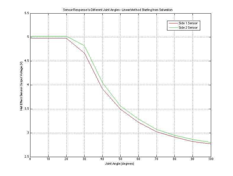
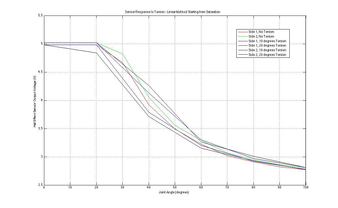
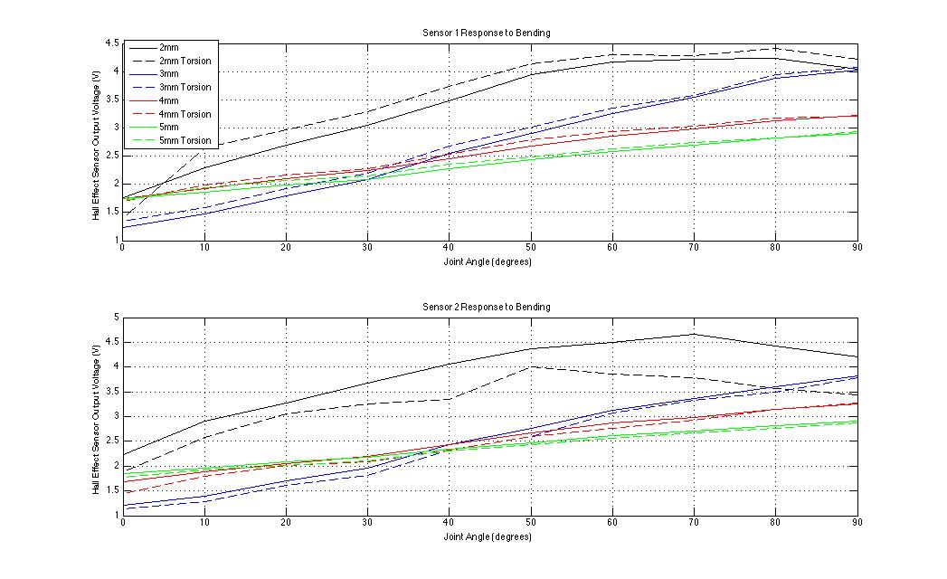
I took extensive readings with the prototype setup I finished at the end of last week, looking at how both joint angle and torsion changes the output readings of the two Hall effect sensors I embedded in the robotic finger joint. Below are two Matlab graphs I made to better visualize and analyze the data I got:
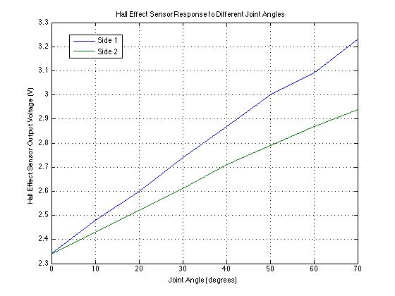
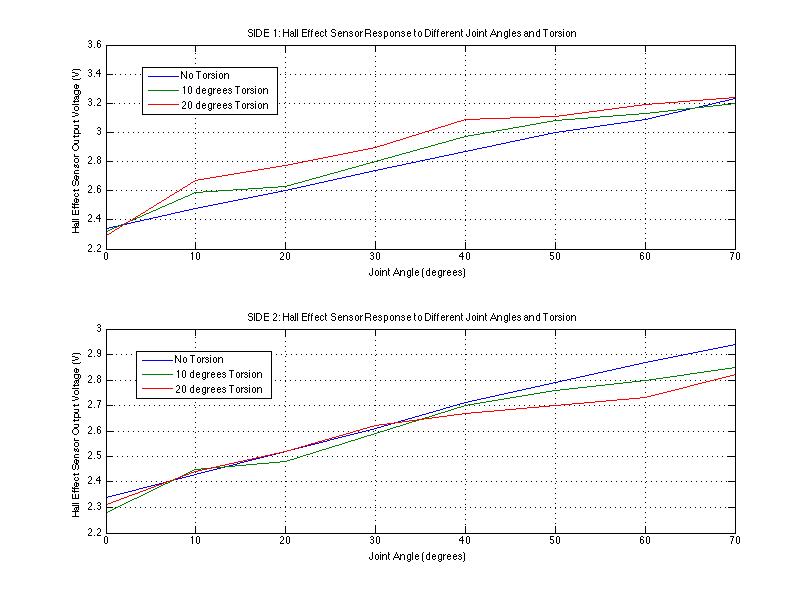
The two Hall effect sensors (labeled Side 1 and Side 2) are slightly offset because I was not able to place the two sensors at a location equidistant from the magnet at all times. The second graph, displaying output readings depending on torsion applied, was a result of bending towards Side 2 - tomorrow I will take readings when applying torsion towards Side 1 to see if the results are similar.
I also plan on making 3D printed models of both the linear and rotation method, each in a basic finger with one joint. I plan on making these models on SolidWorks, referencing both the calculations and geometries of the existing robotic finger that Hannah will send me, as well as previous robotic finger designs. I will be making the joint in a separate 3D printed part for urethane casting, so I can easily take the joint out and put it into another model if there are any issues with the first 3D model. I hope that with this method, I will minimize time needed to make urethane joints if I need to change the 3D model design, especially as casting urethane is such a long process.
19. || July 15
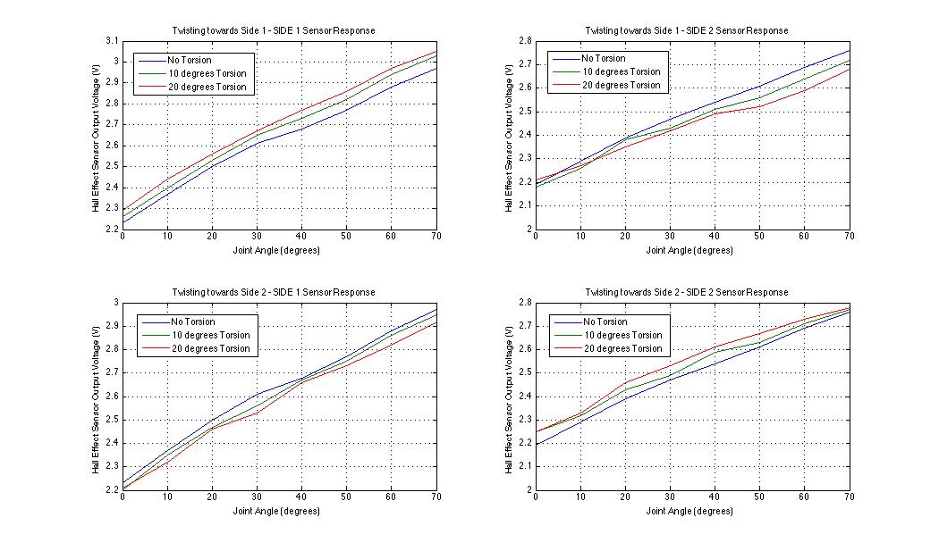
I took more readings with the rotating sensors/stationary magnet setup. Unfortunately I didn't realize that the voltage level was slightly lower than yesterday's (4.7V instead of 5V) which meant that my readings were slightly lower than before. Because of this, I took a whole new set of readings at this voltage rail - joint angle readings, and torsion readings for twisting towards both Side 1 and Side 2. Below is a Matlab graph displaying my results:
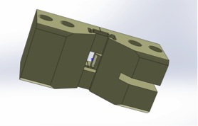
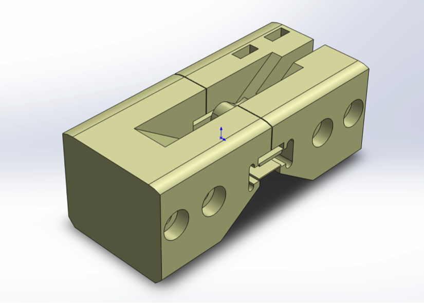
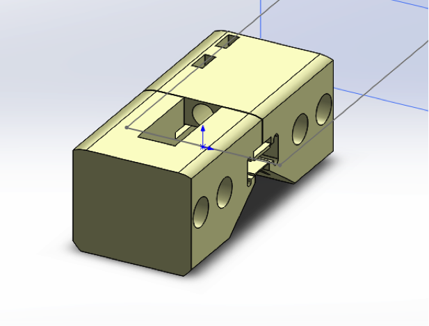
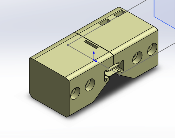
I then had a meeting with Hannah where we altered her original SolidWorks model of the finger joint to fit the sensors and magnet at suitable angles. The new finger design has a cut-out in the middle, so we can use flanges to hold the components in the middle (between the two flexures on either side), and this allows us to put the sensing setup in the middle part of the finger. We decided to print out 4 different versions of this, with sensor-to-magnet distances of 2mm through 5mm. Below are a few pictures showing the slots for the two sensors, the slot for the magnet, and the overall design:
I then altered the design on my own to make a setup for the linear magnet-to-sensors method. The 3D printed material should not interfere with the magnetic field, so I made a bridge at the top of the new middle cut-out section, and made slots for the two sensors, as well as a hole for the longer magnet needed for these linear tests. Below are pictures showing the half of the bridge with the hole for the magnet, and the full linear model setup:
20. || July 16
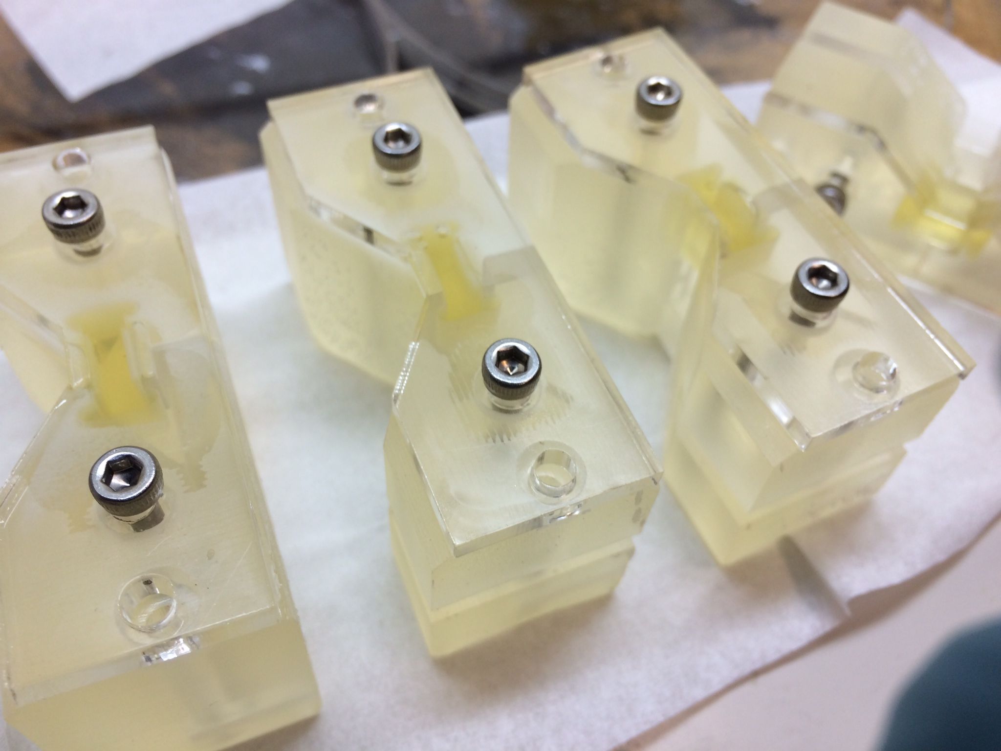
Today we casted the urethane joints of the 3D printed prototypes! Below is a picture of the five 3D prints we made:
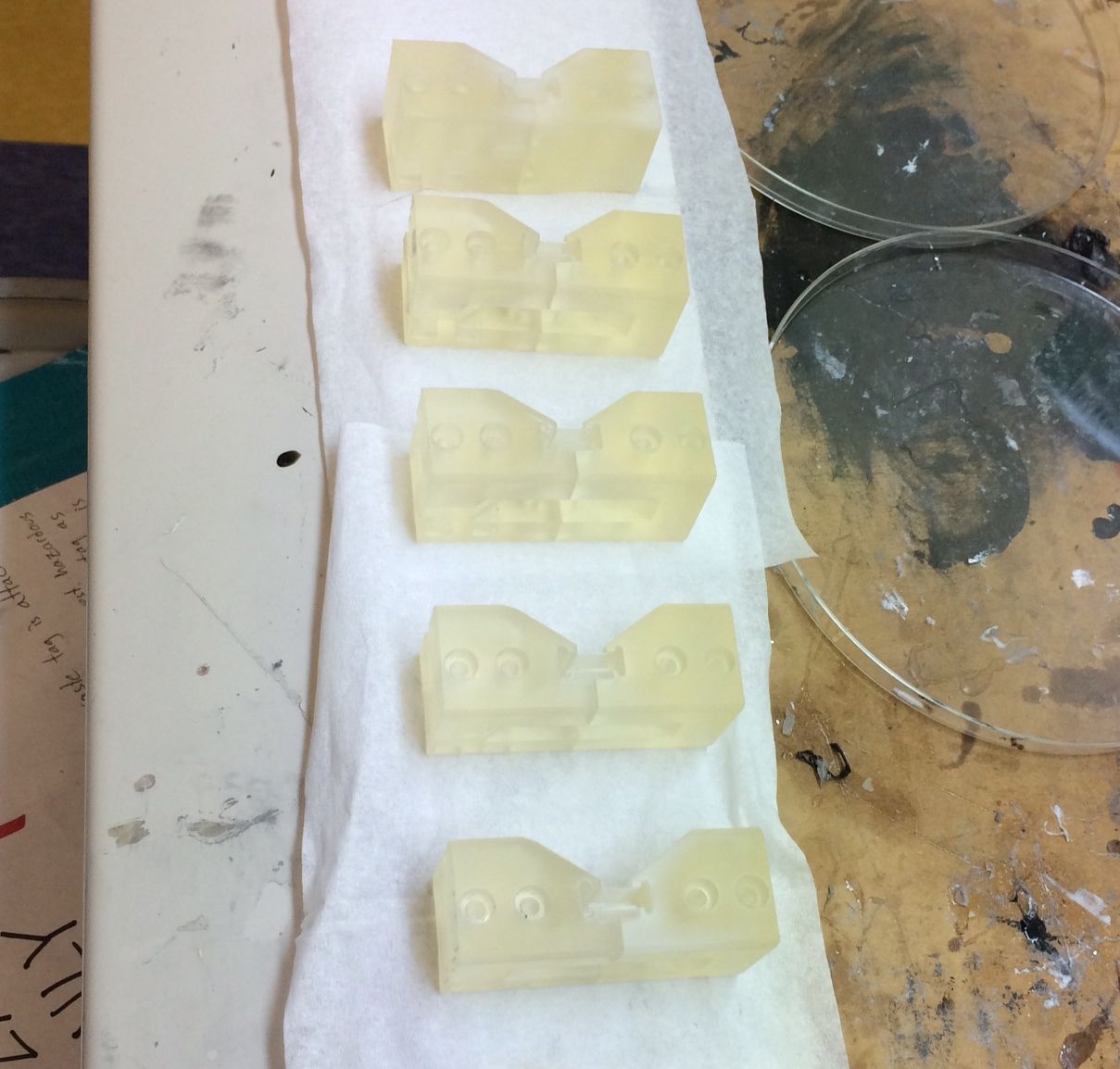
Hannah and I went to the TLTL to cast the urethane joints. We used the laser cutter to print out a flat acrylic part that could be bolted down to one side of the prototype so that we could cast both flexures in the prototype at one time (especially as it is already a very long curing process). The prototypes we made are designed to have a gap in the middle in order to incorporate the joint angle/torsion detection systems inside the prototype, so there are effectively two flexures (one on each side) in each of the prototypes.
The urethane casting process is very similar to the silicone casting process. We mixed 2 parts of a more viscous liquid with one part of a less viscous liquid and stirred vigorously.
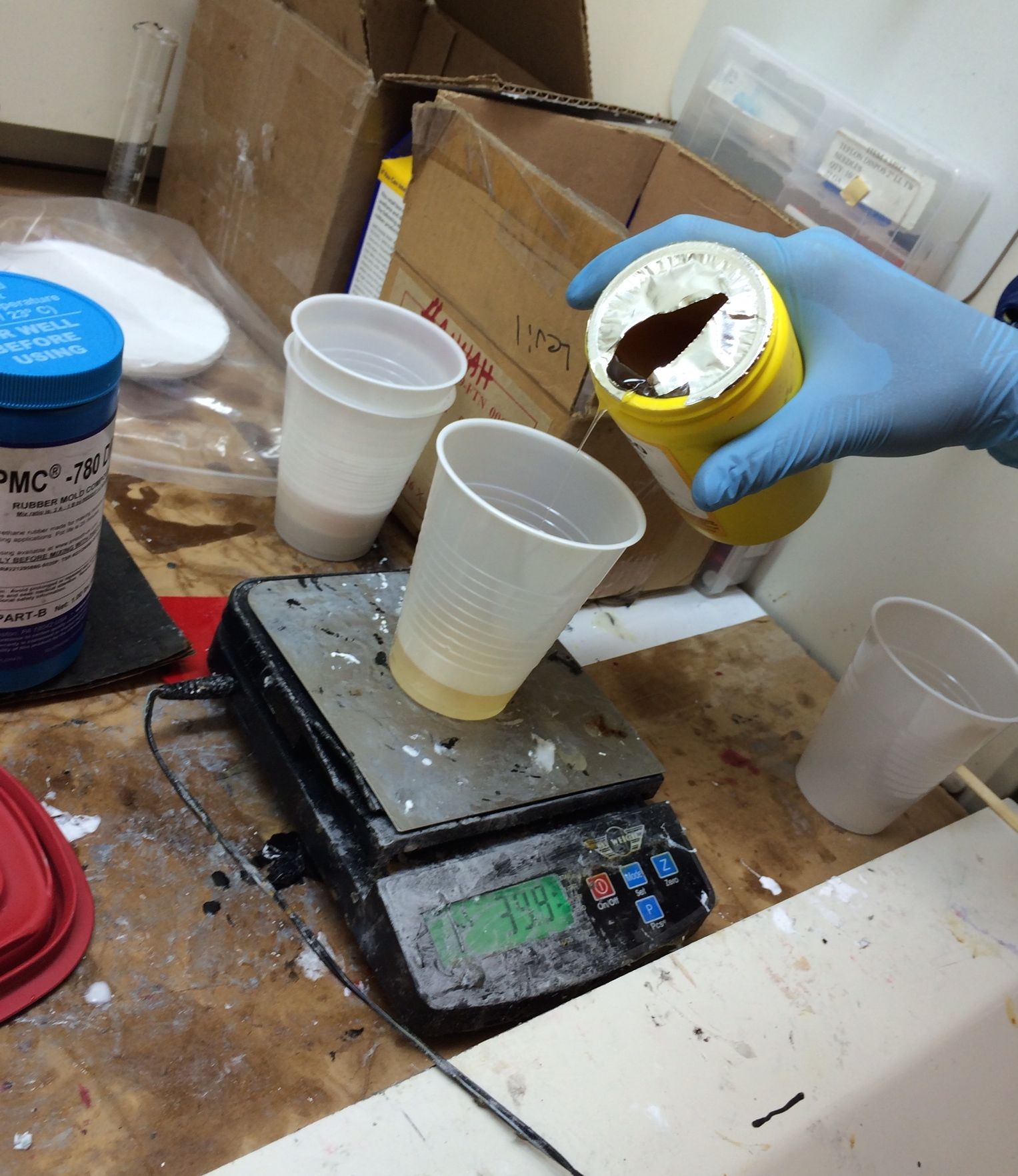
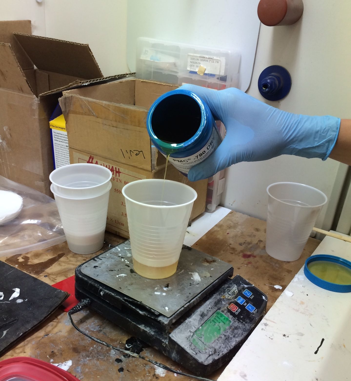
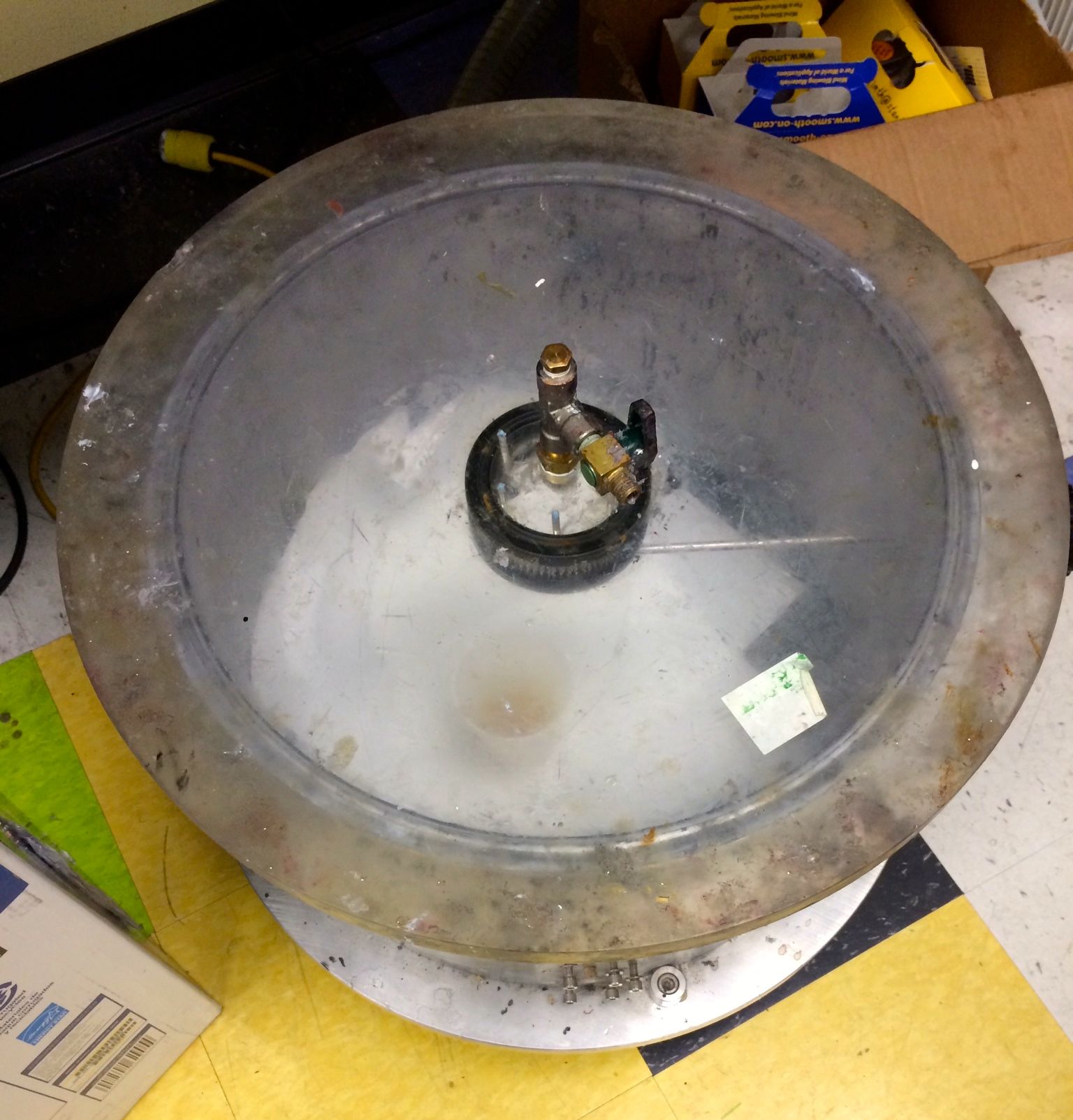
We then put the mixture into a vacuum, which degassed the liquid so that when we cast the urethane there would be fewer bubbles - air pockets/bubbles could lead to faster material crack propagation and failure.
Once the urethane was suitably degassed, we used a syringe to carefully insert the right amount of urethane into the flexure holes. We put a little more than was necessary in each flexure to make sure that the flexure would be completely filled. We relied on the face that when we fastened the acrylic plate on top, the excess urethane would just become a very thin film that we could peel off later.
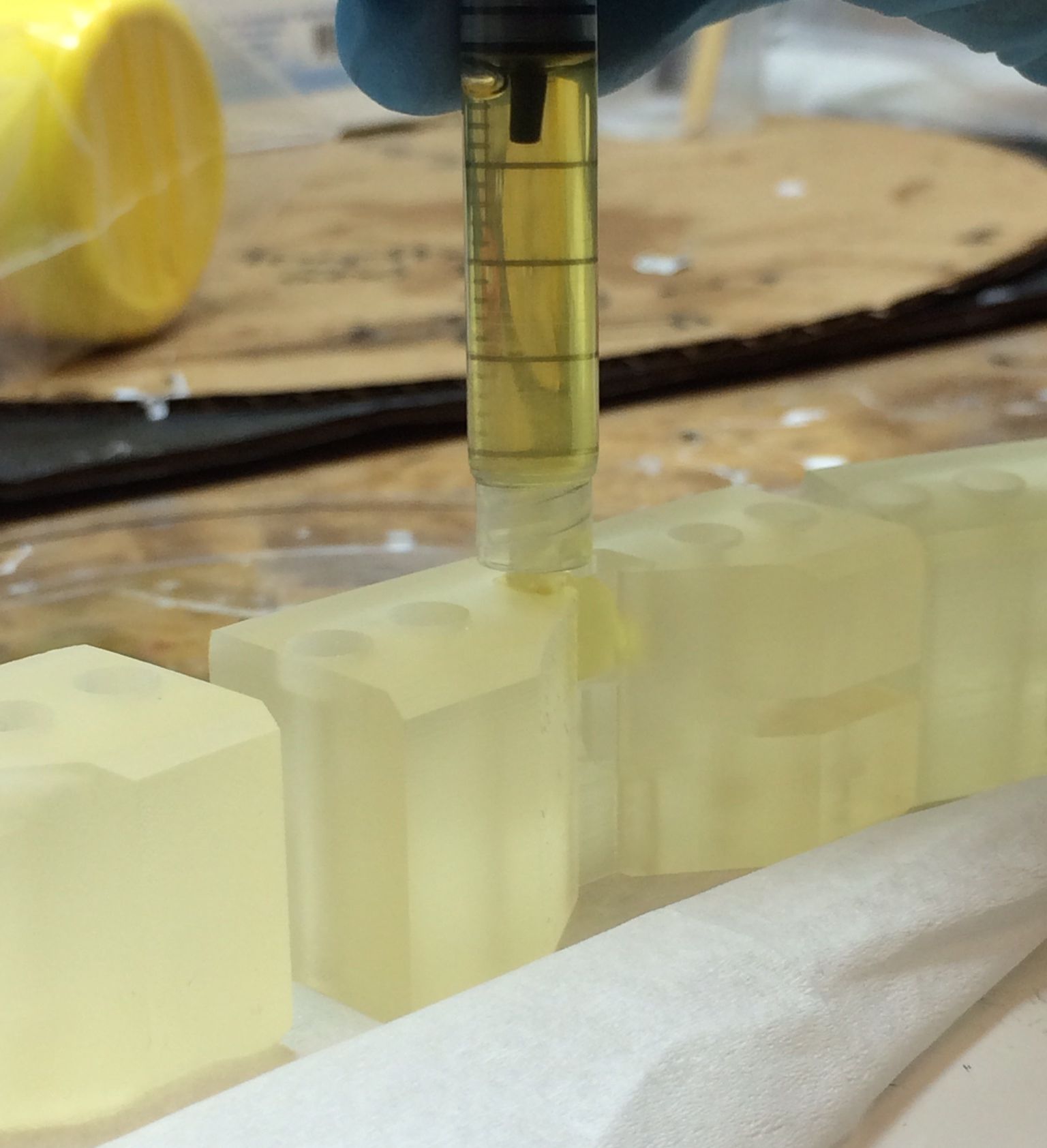
After we filled the all the flexures on one side and fastened the acrylic plates, we turned all the 3D prototypes over and filled in the opposite side flexure with the syringe. We left the flexures to cure - this curing process takes roughly 48 hours.
21. || July 17 + 18
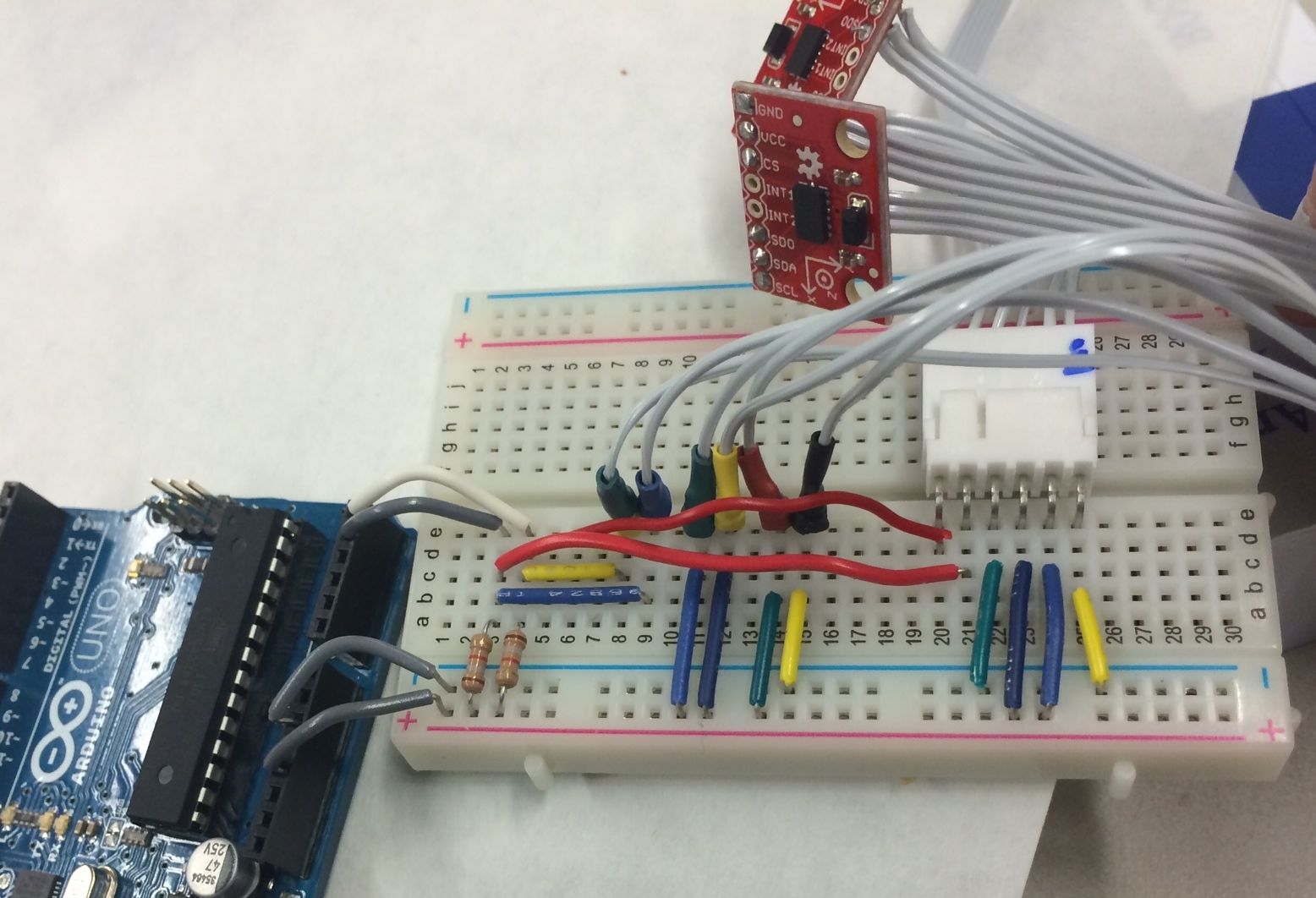
Since the urethane curing process takes 48 hours, I spent these two days helping Shiquan with his part of the Hands project. He is working on putting small tubes into each of the fingers that are attached to pressure sensors - this enables us to read a pressure gradient, which can be used to determine what and how the hand is gripping. I wrote code to get the pressure transducer to communicate via SPI protocol with an Arduino. Arduinos already have a SPI library and assigned pins, but this only allows one byte of data to be read at a time - the pressure transducer has a two byte data output (with the first two bits used as a status check for the sensor). I was able to make the data compatible with both components by using masks and manually controlling the slave select pin. After working on it for some time, and artificially changing the pressure around the sensor with a syringe for testing, I finally got it to work!
I also checked on the urethane joints at the TLTL, and the curing process is going well. I hope to be able to incorporate the components into the prototypes on Monday, and get some more accurate readings. I helped Hannah test some different plastics and epoxies to pot an accelerometer as one of the first steps towards making a waterproof robotic hand. After a few alarming tries (on our first try, we mixed too much of the Task 9 plastic and it melted our cup, and a few of our other tries didn't cure in the indicated cure time), we finally got one of the epoxy mixtures to work and potted the accelerometer for testing.
22. WEEK FIVE
23. || July 21
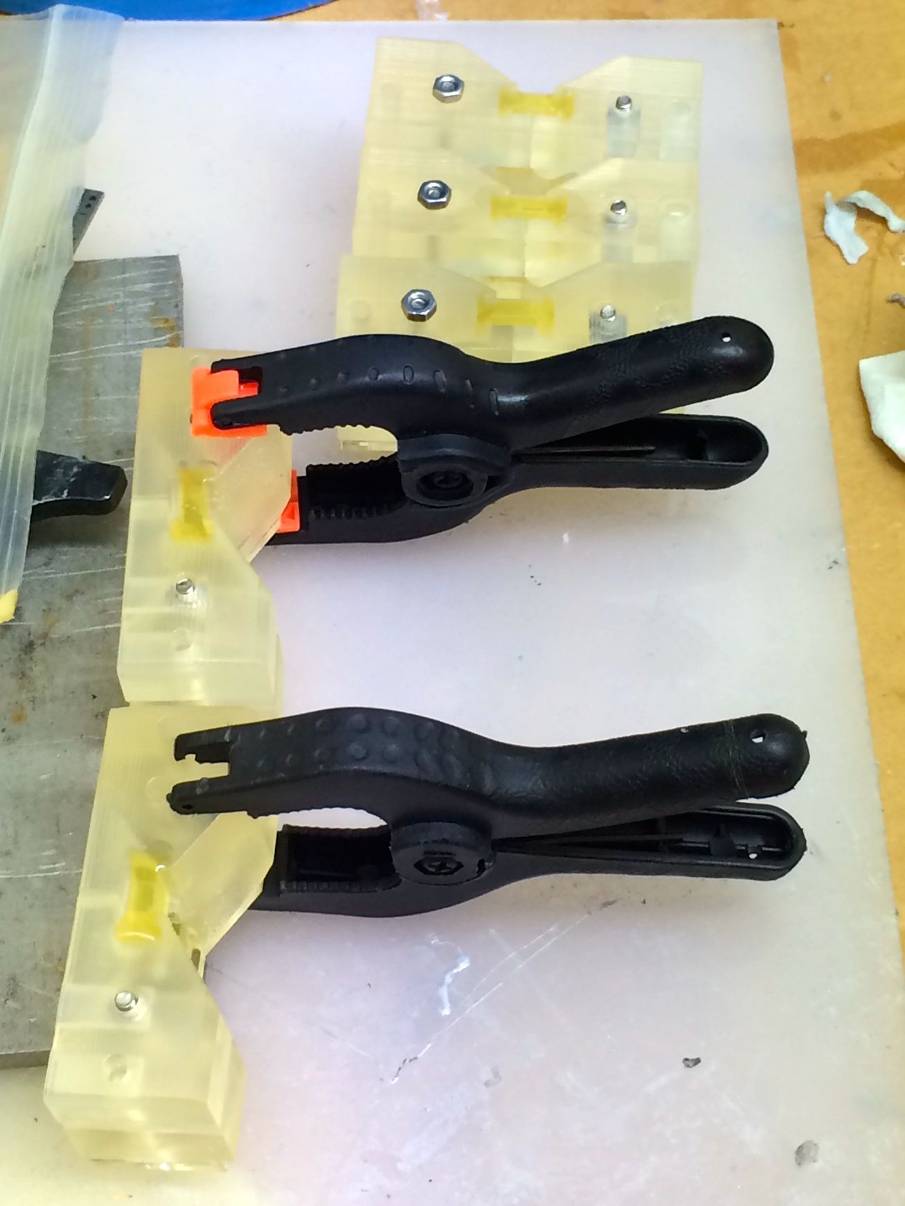
Today the joint prototypes had finally finished curing so I could start setting them up for testing. In the prototypes, we had made thin walls around the flexures in order to contain the urethane as it cured. The urethane attached extremely well to these thin walls, so the normal cracking motions to get rid of the walls and free the flexure did not work. I used a few small tools (screwdrivers, tweezers, etc) to break off these walls to an acceptable degree.
We ordered some of the larger Hall effect sensors for this set of tests, as a major problem I had had before was that the leads of the smaller sensors kept breaking off during testing. The leads on the larger sensors were much bigger and more durable, so I soldered on wire leads to these. The holes and slots for the magnet and sensors in the 3D printed prototypes were sized so that these components could press-fit into the prototype and no glue would be required. I put the components into the one linear method prototype and it fit very well.
I also used a protractor to make an angle measuring device for the prototypes on a spare piece of acrylic. I drew lines out at the different angles, and drilled holes so that the prototypes can be bolted down onto the acrylic, and then the lines can be followed to get accurate angles (line can be seen through the holes of the rotating side of the joint).
24. || July 22
I took readings using the 3D prototype for the linear setup - the two Hall effect sensors directly facing one face of the magnet, with the components getting further away from each other as the joint angle changes. I took three sets of readings - a set of non-amplified readings from saturation (so 5V to 2.5V range), a set of non-amplified from 0V (0V - 2.5V range), and a set of amplified results from 0V to 5V. I plotted the results of the first set of readings (5 - 2.5V) on Matlab for joint angle changes:
I also plotted the torsion readings on the same graph as just the joint angle (w/ zero torsion applied) to see how the sensor readings on each side of the joint were changing with different amounts of torsion applied:
More plots of the linear readings, plus readings for the rotation method prototypes to come soon!
In the evening, I attended the KAUST meeting with the Hands team. I got to meet people on the other teams that are working on different parts of the underwater "mermaid" robot. During the meeting, we discussed the progress of the teams on the various different robot parts (head, body, arms, and of course, hands), as well as the integration of these parts to form the full robot. It was very cool to hear everyone's insights on the underwater robot, as well as all of their creative ideas.
25. || July 23 + 24
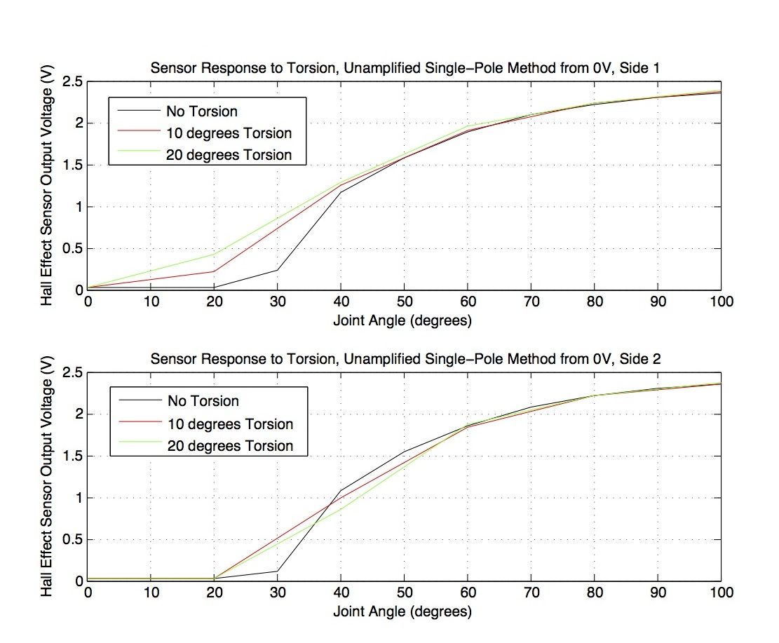
Finally finished characterizing the Hall effect sensors for joint angle and torsion sensing!! I conducted the tests for the rest of the single-pole method setups, as well as the dual-pole methods, which consisted of different sensor-to-magnet radii of 2-5mm. The dual-pole method was setup so that the sensors rotated around the magnet from the north to the south pole, thus increasing the output voltage of the sensors. I plotted an assortment of graphs in order to compare the different setups, and below I have included 3 plots that show my results clearly.
Firstly, here is a plot of the unamplified, single-pole method (starting with the sensors facing one pole of the magnet straight on, and then getting further apart rom this face with bending). The graph also shows the sensor outputs due to torsion on each of the two sensors.
Secondly, a plot of the more linear, dual-pole method with different sensor-magnet radii is below. This clearly compares the output signals of having different sensor-magnet radii in the setup, and shows how linear the data is compared to the single-pole method above. After analyzing this graph, it became clear that the small radii gave larger output voltage ranges, but the larger radii had more linear results. I settled on 3.5mm as the optimal sensor-to-magnet radius, as 3mm had a good voltage range but started to curve a little bit towards the end of the joint angle range, and 4mm had a slightly small output voltage range.
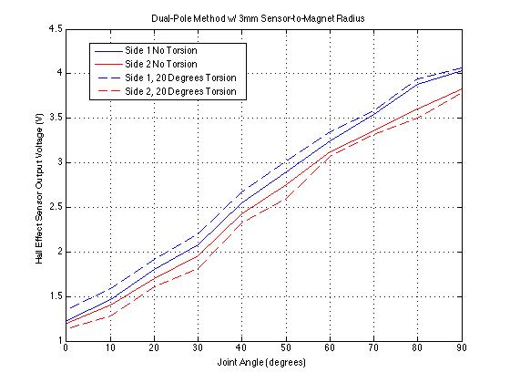
Lastly, here is a plot of the dual-pole setup w/ 3mm radius. This just emphasizes again how linear the output voltage range is, and that the torsion reliably affects the output voltage signal in the same way throughout the whole range of bending motion.
The next steps for the joint Hall effect sensing project is to incorporate the setup (dual-pole method, 3.5mm sensor-to-magent radius) into the finger model with a PCB to minimize the connections and add components (i.e. op-amps and analog to digital converter chips).
26. || July 25
I started working on daisy-chaining SPI for multiple accelerometers today. We're hoping that the accelerometers are compatible with daisy-chaining, and this way we could minimize the number of wires we need in the hand, as the components could transfer data from one another until the data reaches the master chip (in this case, an Arduino).
This project was pretty challenging, especially as I did not have extensive prior knowledge of SPI besides the stuff I learnt when working on communicating SPI with the pressure transducer earlier. I decided it would be best to try and get SPI communication working with just one accelerometer first. The example code on the SparkFun website worked pretty well in communicating SPI with one accelerometer, so I thought it would be worthwhile to see if I could alter the code so that the accelerometer could output only the most important info, which would make the whole process much faster. The specific accelerometer that we are working with outputs data in 11 bit chunks each time (for 4g resolution). Having to convert this signal into a 2 byte message and then try and daisy-chain this message later on could prove difficult, so I tried to minimize this by re-orientating the signal so that the MSB was left-orientated instead of right-orientated, and then cut off the second byte which contained the less significant bits. After lots of trials and tests, I found that the bit used to differentiate between positive and negative was actually at the end of the signal, after all of the data bits outputted, so by cutting of the less significant data I was also cutting of the sign, so this method of truncating the data did not work.
27. WEEK SIX
28. || July 28 + 29
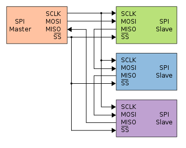
I wired up two accelerometers for daisy chaining following the schematic below:
Daisy-chaining the accelerometers is problematic because the registers that contain the xyz axis data are read-only. There is a buffer register (FIFO) which can store data, but there is no feature that allows me to push data from one accelerometer to the next - it only allows the master component to read the xyz data and then deletes it. I discussed this issue with Hannah, who then took a look at the components and came to the same conclusion, which is a hindrance because we now need to re-think our wiring and the components to select.
29. || July 30
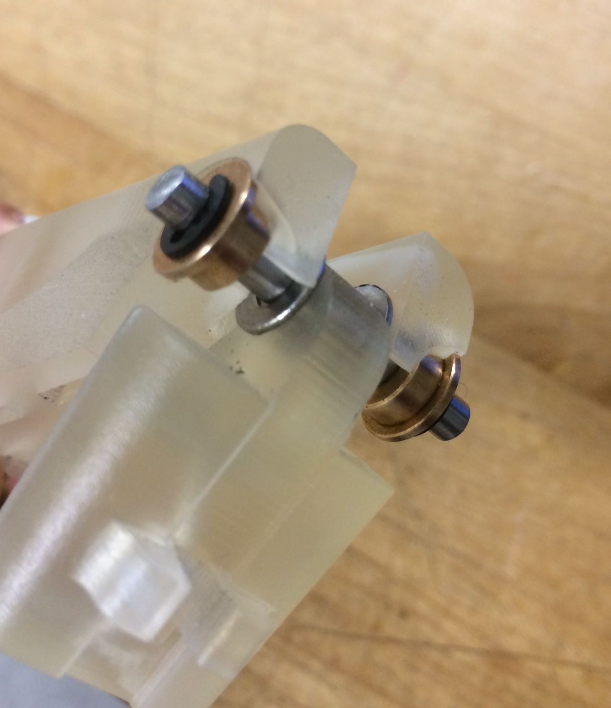
Today I worked on the SolidWorks model of the finger to install pin joints for ease of testing (low friction with bushings and shaft), and alter the suction tube grips on the 3D finger prototype in order to test the suction setup properly. I learned how to extrude multiple-layered holes that fit the bushings well, and also learned a bunch of things about offsets, editing sketches that have already been extruded, etc. Really excited to be able to learn more about using SolidWorks!
30. || July 31
I finished editing the 3D CAD finger model, which ended up also including a hollow tube-like hole on one side of the joint to attach a pressure gauge to and do experiments with that. I'm a little worried that when bending, the two sides of the joint will collide as they rotate around the pin joint - I hope to learn how to use the assembly functions on SolidWorks to put together the pin joint on the computer and see if they do indeed collide. Here are a couple of pictures of the finished prototype, showing the layered hole for the pin joint, the hollow tube-like hole for the pressure gauge, and the suction holders on each side of the joint.
Tomorrow is the BDML summer BBQ! Bobby and Mark already picked up the food for tomorrow, so I designed the poster to advertise the BBQ:

I also helped Hannah with the sensors part of the presentation for tomorrow, and made some graphs to display data from the Hall effect characterization clearly for the presentation.
31. WEEK SEVEN
32. || August 4
Today Shiquan showed me how to use the assembly feature in SolidWorks to put together the CAD pin joint finger model in order to check that the parts would bend without collision. Below is a picture showing the bent assembly, and verifying that the parts can bend around the pin joint properly.
Shiquan modified the suction holders with the dimensions I gave him, and we are hoping to print out a 3D model tonight so we can start testing tomorrow.
I also worked on getting the ADXL345 accelerometers to communicate via I2C protocol so we can minimize wires and have all of the accelerometers hooked up to each other, but still get all of the data. These were the same accelerometers that we had initially tried to use SPI daisy-chaining to communicate with. I got the Arduino code working for this - it was similar to the SPI code for one accelerometer, except with different functions from the Wire library rather than the SPI library.
33. || August 5
Today I worked on getting I2C communication to work with two accelerometers. I had previously gotten I2C working with the ADXL345 chip, but we only had one of those available, so I used a MMA8452Q chip for the second accelerometer. This chip had different initialization requirements and different register addresses, so it took me a little while to read through the fairly convoluted data sheet and get all of the relevant information. After some time coding and wiring up the accelerometers, the MMA8452Q chip still wasn't outputting any numbers, and strangely the ADXL345 chip output strange numbers when connected up to the other chip - I suspect that I had not initialized the MMA8452Q chip properly, but I couldn't find what I was missing even after reading through some example codes for the chip and reading through the data sheet again.
Thankfully, I got my hands on a second ADXL345 chip from Caitlin, and changed the code around for two of these chips. Strangely only one accelerometer was outputting data properly, and the other one was just outputting zero. I plan to look into this problem tomorrow.
We also had a Hands team meeting in the afternoon, where Hannah showed us a Gantt chart she made to display the timeline for the project. The deadlines for a working hand for KAUST and the ICRA paper are both in early October, so we still have a lot of work ahead of us.
34. || August 6
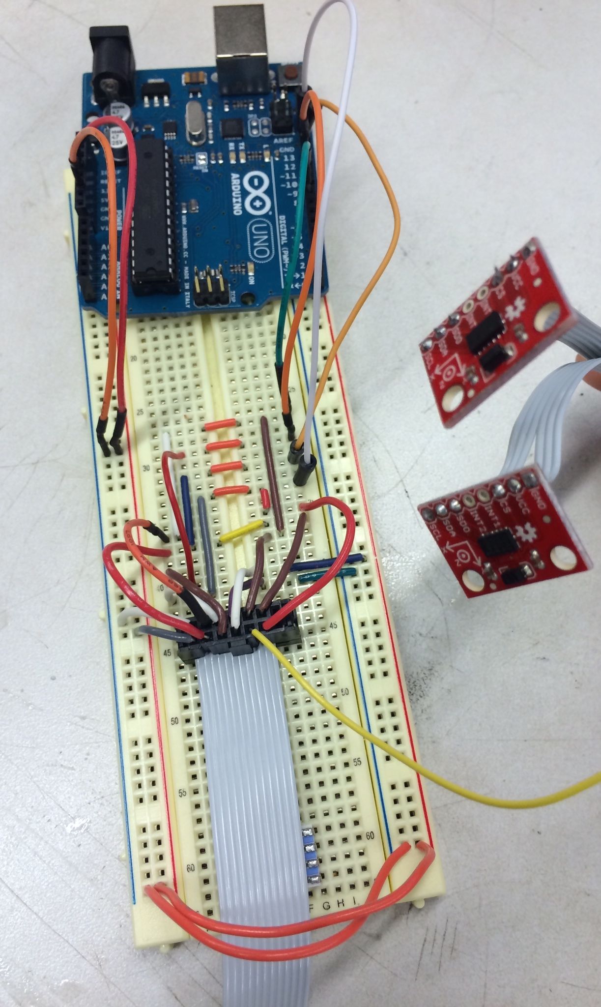
Looked into the problem with I2C communication of two ADXL345 chips. I took out a couple of wires while debugging the first setup (with the two different accelerometers) and forgot to plug them back in when I changed the setup... so it works now! Below is a picture of the setup:
Since the IR and PVDF methods of detection in the fingertip are not ideal, we are trying to incorporate a Hall effect and magnet setup to detect forces in the fingertips. I brainstormed with Hannah and Morgan on the different setups we could use (including casting the magnet into urethane and then bending the urethan around and slotting it into the finger so that it acts like a kind of spring), but eventually we decided to just try to cast the magnet and sensor into a solid block of urethane or other material for initial testing. We are trying to avoid the need for more wires inside the finger, so I spent a few hours researching Hall effect sensors that had a digital serial output. Unfortunately, most of the digital output sensors were latching, which we did not want, so we decided that the best way for now is to use an analog sensor and use an analog-to-digital converter to change the output signal.
Tomorrow I will start designing a CAD model that we can use to cast urethane/silicone into so that we can seal the magnet and sensor into the prototype and start testing soon. I'll also be helping Shiquan experiment with the suction prototype, and start characterizing that setup.
35. || August 7
Today I designed a CAD fingertip sensor prototype for a Hall effect sensor and a magnet cast into urethane. I made a small setup that had a slot for the Hall effect sensor and leads, and a flange for the magnet that could break off once the urethane had been cast around it and pressure applied to the setup. I ran my design by Hannah, who suggested that a) I make the flange for the magnet thinner (2mm x 1mm) so that it is easily breakable, possibly including a notch in the middle, b) make the compartment for the magnet bigger, so that it isn't a press-fit (or else the flange would break easily when initially inserting the magnet), and c) putting a fillet on the edge of the magnet compartment so that there isn't an edge to break the urethane when pressure is applied on the setup during testing. I am also going to look for more magnets on K&J, ordering more of the thin magnets that I have been using, as well as some thinner and wider magnets for testing.
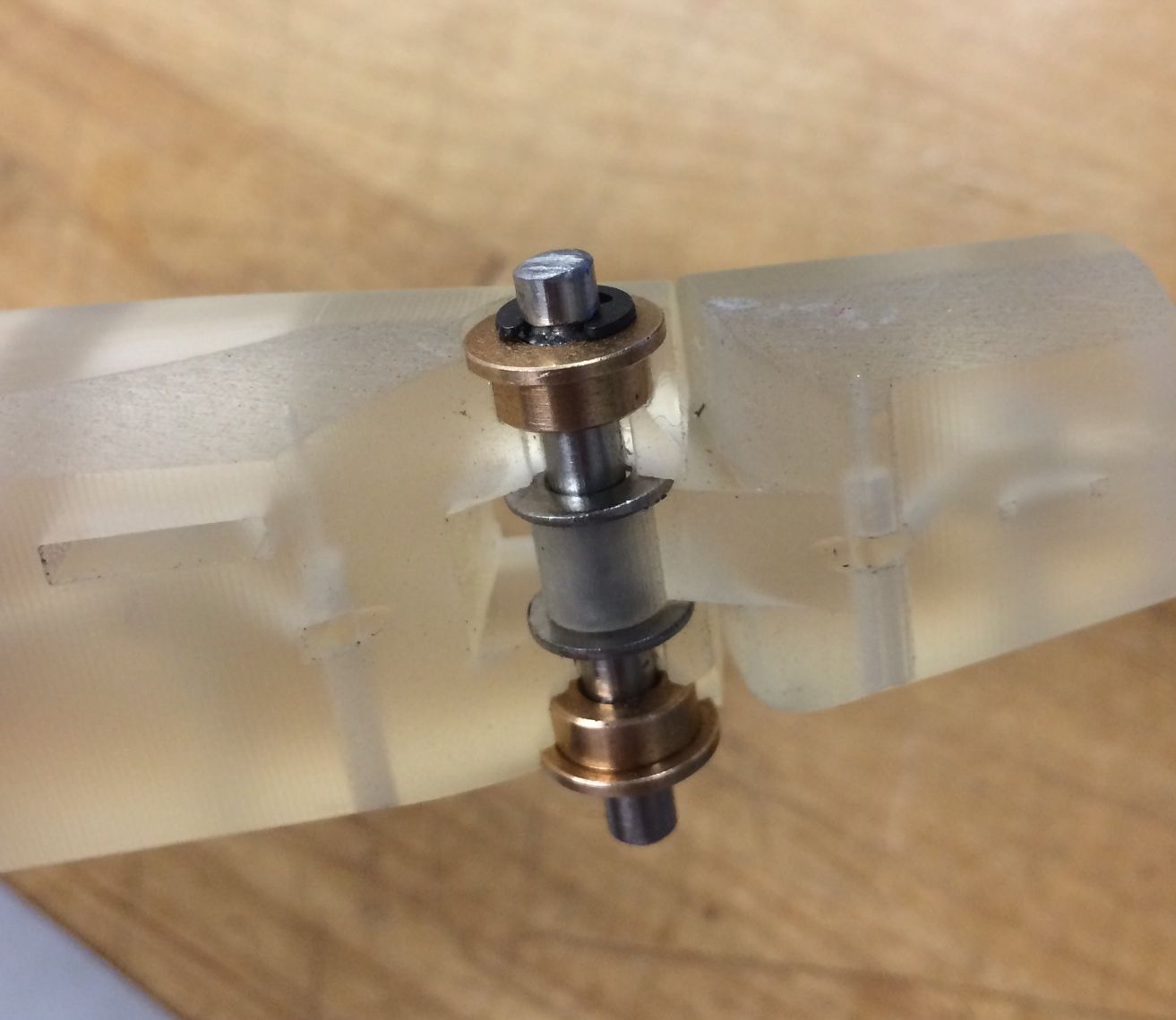
Shiquan printed out the suction prototype with the pin joint holes that I designed, and I put that together. I had to machine notches on the shaft so that I could put retaining rings on the outsides of the bushings to ensure that the shaft did not slip (I had to do this twice, as during the first time, I made the notches too close together so it didn't fit the design). The bushings and middle shaft-holder were able to press fit into the model as designed. I added metal stand-offs on either side of the middle shaft-holder to make sure nothing could wiggle about while bending, and this also made the pin joint less friction-prone. All in all, the pin-joint prototype was a success! Below is a picture of the prototype:
Tomorrow, I'll make the adjustments on the CAD model and hopefully get the 3D printing job started, order some more magnets from K&J (and learn how to use the P-card!!), as well as help Shiquan start testing the suction prototype.
36. || August 8
I finished the CAD design I was working on yesterday, and added the edits that Hannah suggested. I made different variations of the design for various geometries (different magnet and flange sizes). I gave these designs to Shiquan for 3D printing, and hopefully I'll have the models early next week. Below is a picture of the CAD model:
I helped Hannah de-bug her Arduino code for I2C communication with an A2D chip, but we ended up coming to the conclusion that the printed circuit wasn't working properly, causing us to get a strange output from the chip. I also made my first purchase with the BDML P-card, and bought some magnets from the K&J website for prototyping. Additionally, I ordered some more of the ring-shaped magnets I had previously characterized for joint angle detection.
Next week, I will start the process of testing the fingertip sensor prototypes - casting urethane or silicone into the prototypes and starting to characterize the setup.
37. WEEK EIGHT
38. || August 11
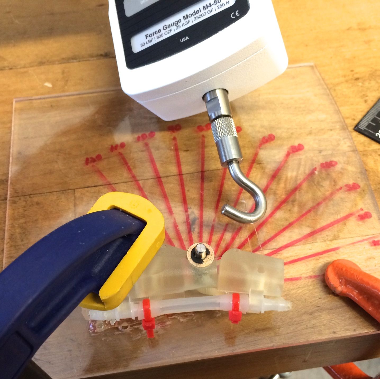
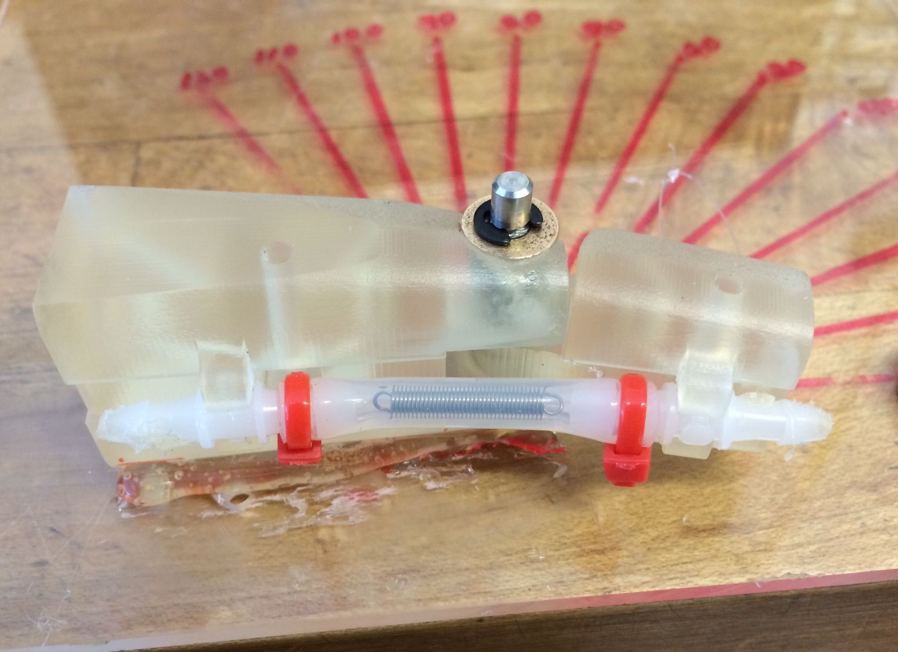
The 3D printer was unfortunately broken, so I started characterizing the suction tube stiffnesses while I wait for my fingertip sensing prototypes. Shiquan had ordered 4 different kinds of tubing, which are displayed in the picture below:
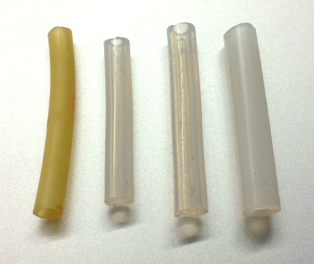
I altered the acrylic angle measuring plate I had made for the joint angle testing to fit the suction prototype. I then used different lengths of tubing (ranging from 3.5mm to 4.5mm) and conducted tests with and without springs inside the tubes. As the tubes bent when the angle of the joint increased, the inner hole in the tube flattened out, so I did some tests with a spring inserted in this inner hole to maintain the shape of the hole as the joint bent. In addition, some of the tubes slipped off the plastic end parts as it stretched (this was either because of the short length, or because of having a larger inner diameter than the plastic end part was made for). I used zip ties to fasten the ends of these tubes. The setup I used to test tube stiffness is shown below:
39. || August 12
Today I was able to complete the tube stiffness tests. These tests were fairly rough, with readings taken at 30, 60, 90 and 100 degrees. We were looking for a tube that had a good amount of pre-load so that after around zero degrees, the force needed to bend the joint would be fairly consistent or start to decrease. I made some graphs on Matlab displaying the data I got so I could figure out which tube type and length was the best for this application. Below are a couple of graphs that I found were the most helpful:
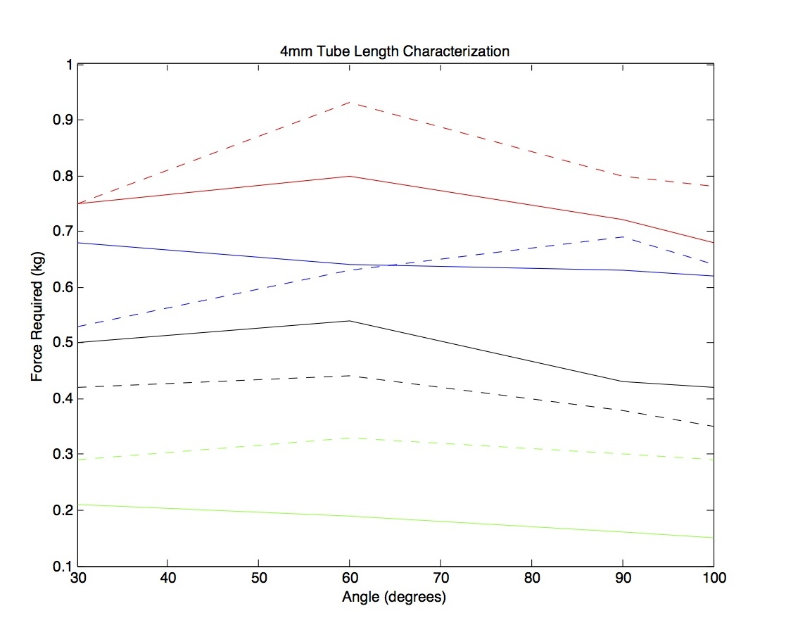
This graph showed clearly how the different tubes compared to each other for bending. The blue represents the opaque white tubing, red is the stiff clear tubing, green is the yellow latex tubing, and black is the flexible clear tubing. All dashed lines represent data taken with a spring inside the tube.
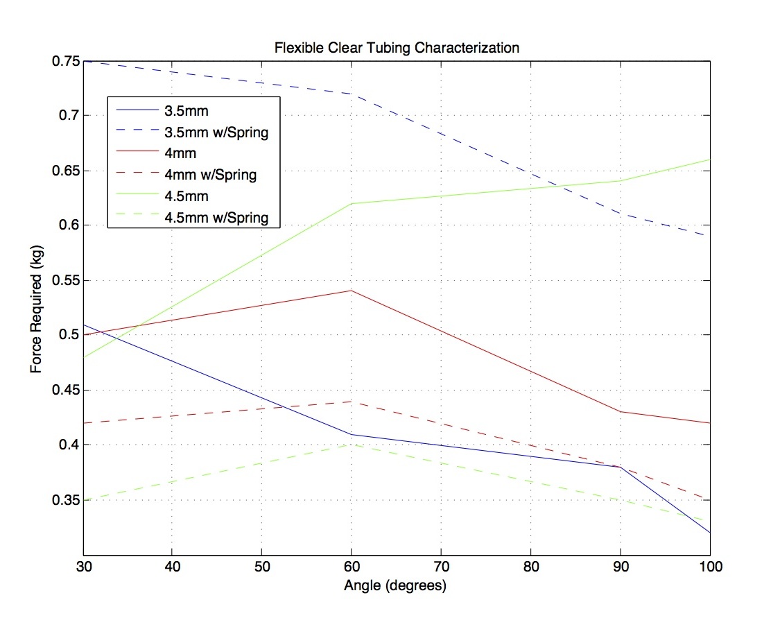
The data here is a little confusing (as the tests were pretty rough), but it seems like the 3.5mm w/spring tube had a good amount of pre-load and a good downwards sloping gradient.
During the Hands meeting, I got some great suggestions and advice for additional tests to really nail down the best tubing for this suction application. Instead of a small tension spring (like the one I was using during the tests), I will try out a longer flexible compression spring - this will start out compressed, and as the joint is bent and the tube is stretched, the compression spring will expand with the tube.
Hopefully the 3D printer will be fixed soon and I can get started on testing the possibility of a Hall effect sensing setup in the fingertip. There are many issues with having magnetic sensing so close to the outside of the finger, so Mark suggested looking into magnetoresistive sensors, which could work out better.
40. || August 13
I did some research on magnetoresistive sensors, starting with the paper that Mark sent me yesterday, and then branching out and looking at some more comparison and application papers for the sensor that were available online. After a while, I found a really clear comparison of Hall effect vs. magnetoresistive sensors:
For the AMR sensor: (AMR = anisotropic magnetoresistive)
- High sensitivity and a low-noise signal.
- A large operating distance from the magnet is possible.
- Angle of measurement is up to 180� but with higher angle sensitivity.
- Possible disturbance from external stray fields.
For the Hall sensor:
- Because of internal pre-amplification, sensitivity is comparable.
- Sensor functions only in the near field of the magnet.
- Angle of measurement is up to 360�.
- Possible disturbance from external stray "dipole fields."
It seems to me like on the whole, the sensors operate in very similar ways, but the Hall effect sensor might be better for our application since it only functions near the field of the magnet. The magnetoresistive sensor has a larger operating distance, so this could increase the amount of noise we get from grabbing ferrous materials - a major concern since the application for the sensor would be in the fingertip.
In other news, I'm hoping to order the compression spring for the small suction tubing tomorrow for testing. I'm also hoping to use Dragon Skin 10 silicone for the fingertip prototypes, and I will also order some more of that if we're running low at the TLTL.
41. || August 14
The 3D printer was working today, and Shiquan was able to start printing the fingertip sensing prototypes! It will take roughly 16 hours to finish the job, so I'm hoping to have them tomorrow. He also showed me how to use the KAUST P-card, which I used to purchase springs for the suction tube system that will go on the back of the hand.
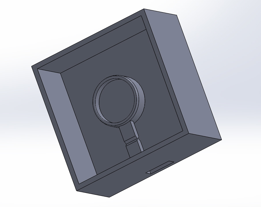
I wanted to try another method for casting the magnet into silicone for the Hall effect tactile sensing, so I drew up parts with SolidWorks that I can laser cut and glue together to make a quick mold for casting. I plan to cast some silicone into the mold, and then place the magnet in and cast over it to secure the magnet in place. This means that I will not need the magnet compartment and flange, which might otherwise get in the way of the tactile sensing. The magnets I ordered from K&J should be arriving on Monday, so I can start prototyping and testing when those get here.
I also started doing some rough testing of how ferrous tools interact with the magnet in the Hall effect joint setup, and how much the output signal of the Hall effect sensor is affected. It seems like the signal does change, but this change is not significant enough to cause major problems. I will do more precise testing tomorrow.
42. || August 15
I did some more experiments with various ferrous tools and the Hall effect joint angle detection prototypes. I put two Hall effect sensors back into the 4mm sensor-to-magnet distance prototype (which is close to the 3.5mm distance we had settled on as a result of earlier experiments). I used a hammer and a metal file, both of which are ferrous tools, and placed them very close to the joint angle sensor setup as if the hand were grasping the object. The picture below shows the placement of the tools:
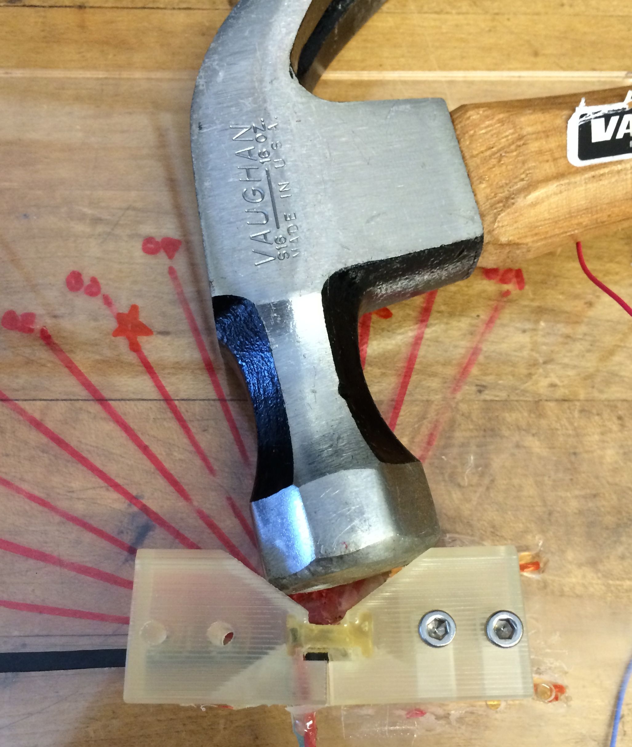
I took readings at joint angles from 0 to 110 degrees for no ferrous material interaction, a hammer, a metal file, and a small screwdriver making contact with the north and south poles of the magnet in the joint. Below is a graph of my results:
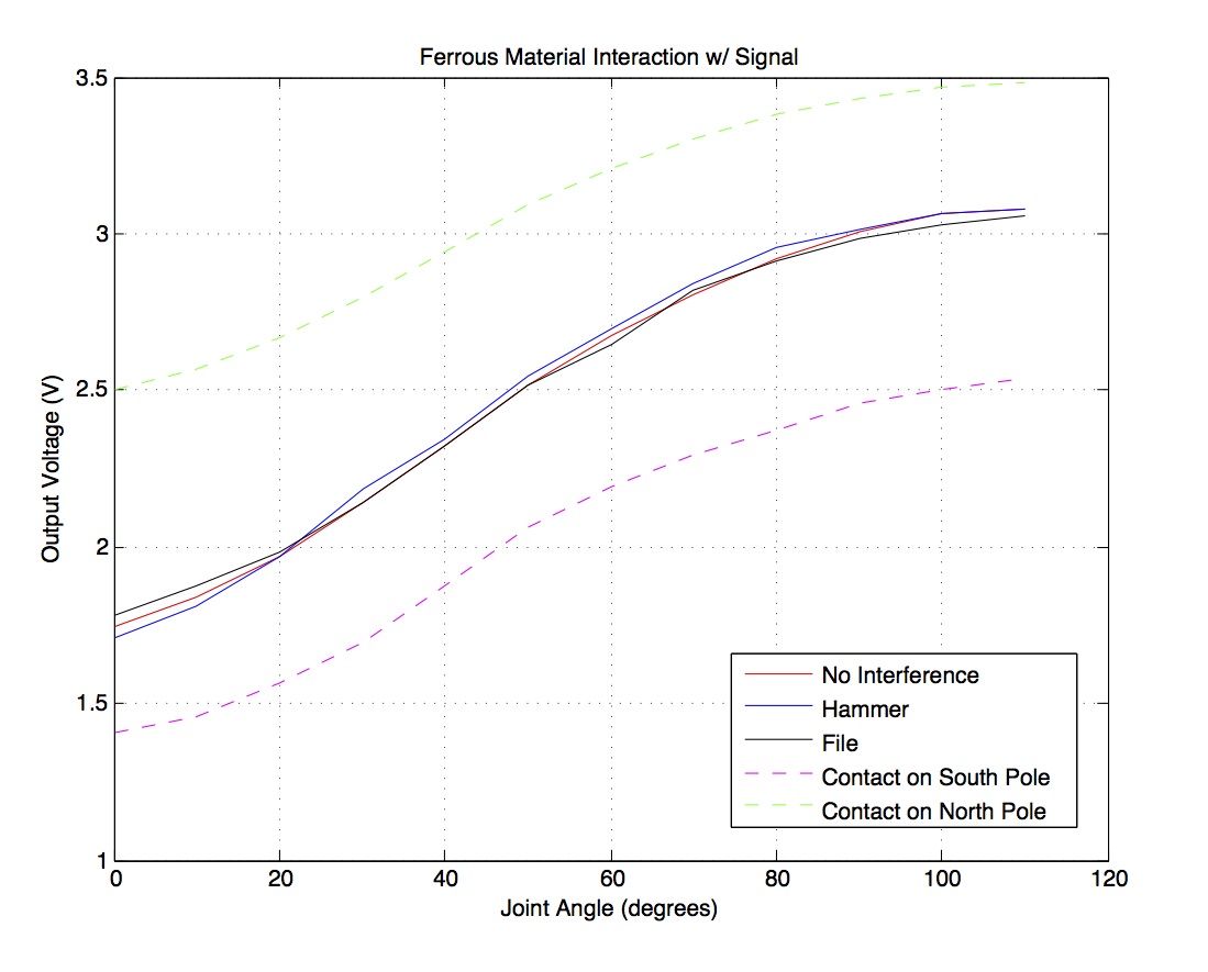
The results clearly show that we need to encase the magnet well enough so that no small ferrous materials can make contact with it, but larger ferrous tools that we may potentially be grasping with the hand will not affect the joint angle output signal significantly enough to be a problem. This is great news, and means we can stick with the dual-pole Hall effect sensor setup!
43. WEEK NINE
44. || August 18
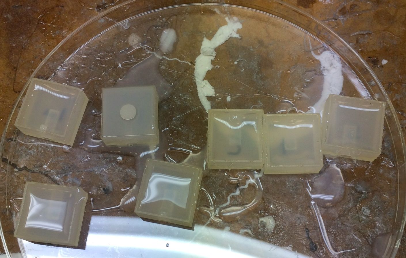
Today I got the magnets from K&J in the mail, and my fingertip prototypes were successfully 3D printed, so I was able to cast the silicone (Dragon Skin FX-Pro) and prepare for the characterization tests for the Hall effect tactile sensors. Unfortunately, while cleaning and casting, most of the flanges on the prototypes broke. The flanges were designed with a notch in the middle so that they could break easily once the silicone was casted and pressure was applied to the "fingertip", but they broke a little too easily and only one prototype still had a flange intact by the time I was able to start pouring the silicone into the prototypes.
This actually turned out to not be a major problem, because I had planned to make a set of new prototypes with the laser cutter that were effectively just a cavity where I could cast half of the silicone, insert the magnet, and then cast the rest of the silicone. This meant that there would be no 3D printed material in the way when we press down on the silicone to change the distance between the magnet and the sensor.
Here is a picture of the half casted prototypes with the one prototype (with flange intact) to compare:
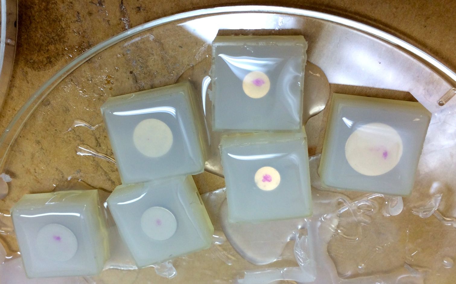
And the fully silicone-casted prototypes:
45. || August 19
Started doing some rough testing of the completed prototypes for the Hall effect tactile sensing. I used a standoff to put on top of the silicone and apply force over a certain predetermined area using the distance measuring stand. Below are some pictures showing the setup:
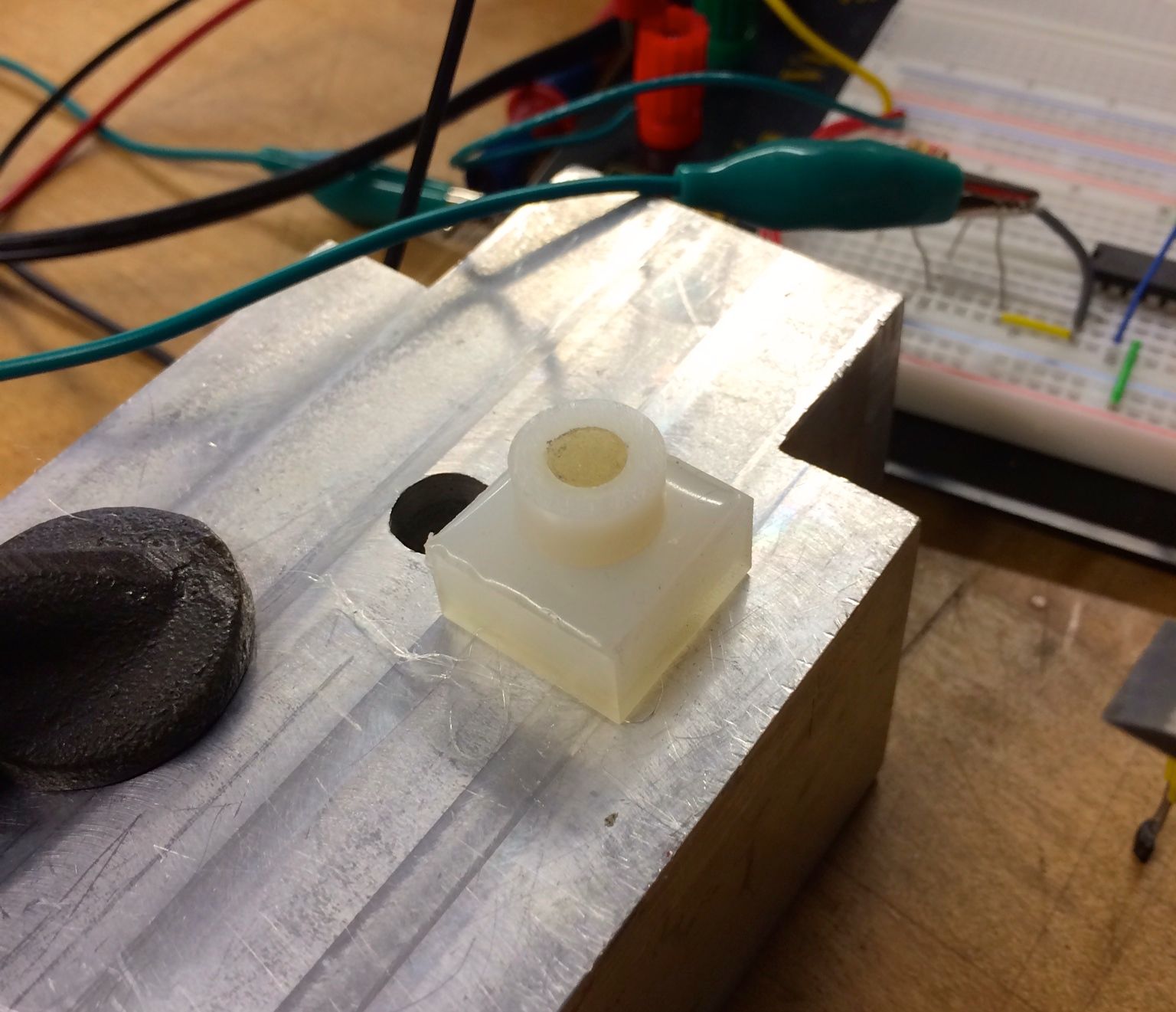
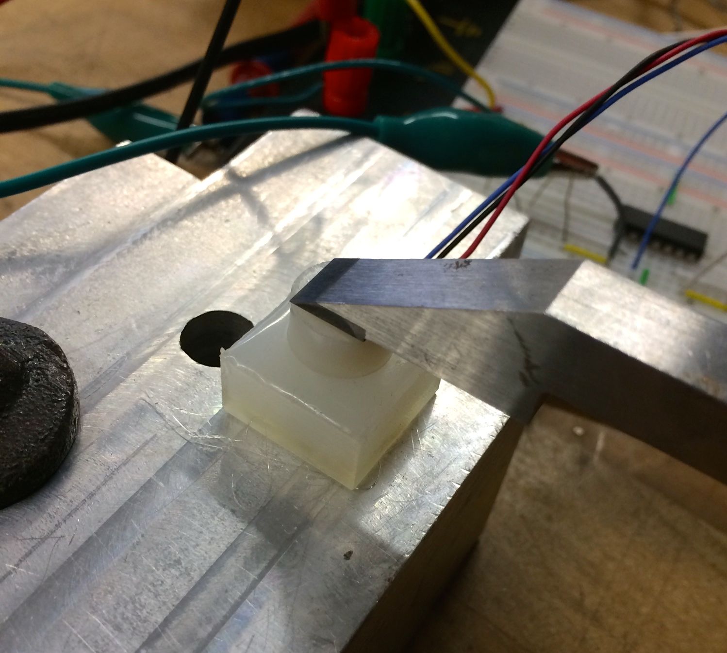
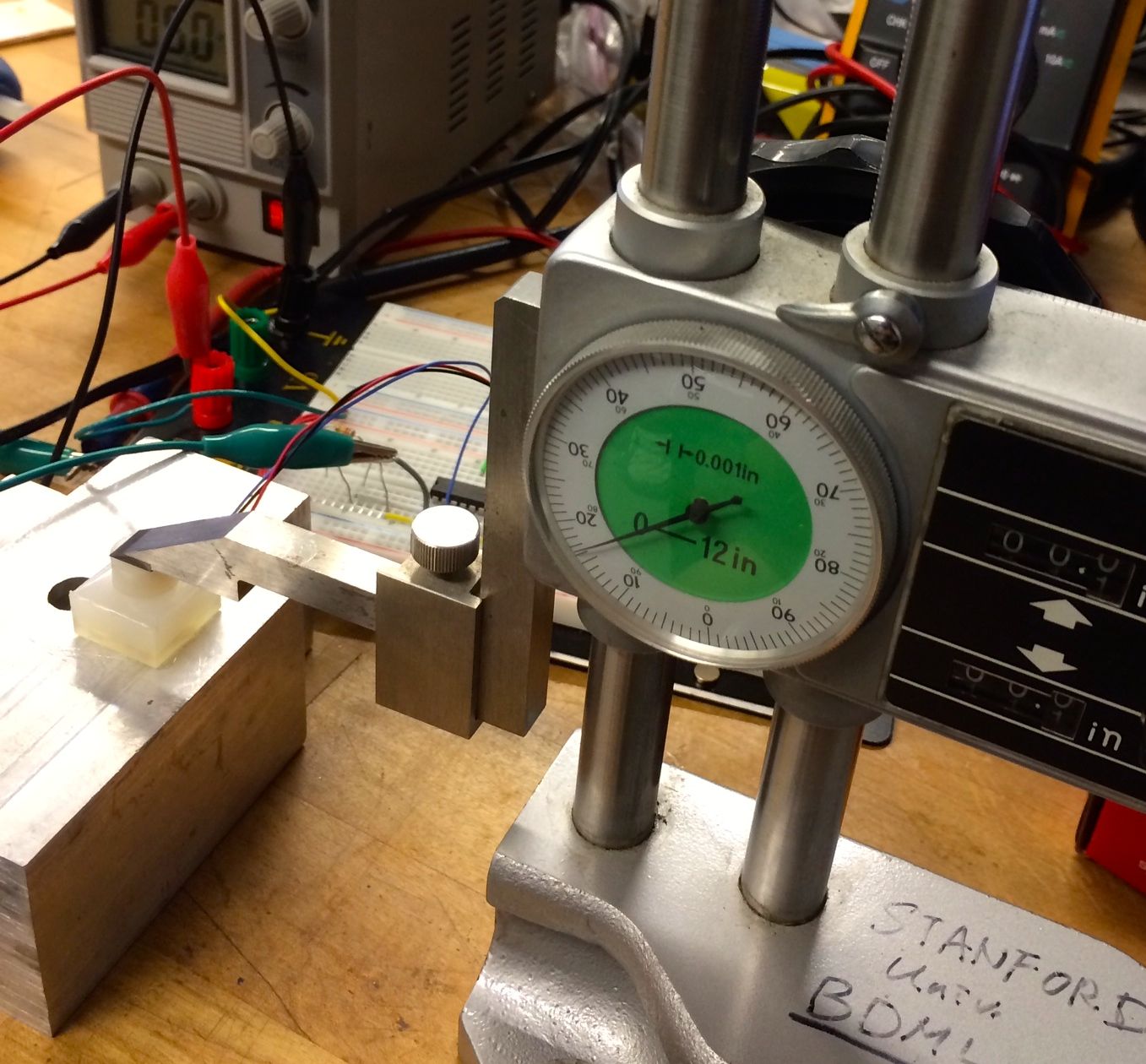
I got readings from these prototypes, but I wasn't able to cast the magnet into the silicone at the same distance away from the sensor in every prototype. I will redesign the prototypes so that they will be more consistent and thus produce better results.
46. || August 20
I changed the design of the prototypes for fingertip tactile sensing so that I could more easily do the 2-part silicone casting method to cast the magnet into the prototype. I'm hoping to have them printed out soon so I can cast, but there have recently been some problems with the 3D printer. I also worked on my slideshow for the presentation I will give in Friday's lab meeting about all the projects I worked on this summer.
47. || August 21
I worked with Hannah on getting I2C communication working between the Arduino and the encoder we plan to use in the hand, and managed to get this to work after we realized that we were initially using the wrong device address - the data sheet for the encoder was pretty convoluted and it did not make it clear how to determine what device address to use. We eventually managed to get I2C communication working simultaneously between an Arduino and an encoder, accelerometer and ADC chip, which is really exciting!
The compression springs I ordered last week for the suction tube tests came in today, so I tested some of the tubes at different lengths with these springs. I ended up having to use two small screws (one for each end of the tube) so that the compression spring did not push up and out of the tube. The springs are a little stiff, so if they are not held in place properly when the are compressed, they squeeze past the two plastic end parts which is not what we want. I will continue testing tomorrow.
48. || August 22
Today I presented all of the work I have been doing this summer to the lab, which went really well! I got some great feedback on some of the experiments I did, and it was really interesting to hear about the work Mark has been doing this summer.
I also continued with the suction tube stiffness tests now that I have the new compression springs. After taking some readings, I came to the conclusion that the setup isn't optimal for the data I need to collect - as I pull the joint to different angles using the force sensor, the friction from the acrylic plate underneath holds the sensor in place slightly, which alters the readings I get. The sensor is also not completely flat and at the same level as the joint it is pulling. I plan to re-think the experimental setup so that these problems don't hinder the experimental data.
49. WEEK TEN
- Worked on poster for the SURI presentation on Friday
- Wrote my SURI reflection
- Attended Hands meeting on Tuesday where we debriefed on progress this past week, had a good discussion on what would be a good setup for the suction tubes/springs on the back of the fingers. I did some more research on other possibilities for tubes and springs, and looked at possible clamping of one long tube or spring for a whole finger, rather than breaking these up for each individual joint.
- Preliminary discussions with Hannah and Shiquan about our ICRA paper
- Discussions about short-term goals and things I can work on after the SURI program