new web: http://bdml.stanford.edu/pmwiki
TWiki > Main Web>TWikiUsers > JuliaLee>SummerBlog (30 Oct 2010, MarkCutkosky)
-- JuliaLee -
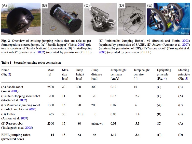
Kovač, Mirko, Manuel Schlegel, Jean-Christophe Zufferey, and Dario Floreano. "Steerable miniature jumping robot." Autonomous Robots (December 2009).
June 16
Excited to get started!- Talked with Alexis regarding possible research projects for the summer and settled on jumping, but also curious about electronics/sensing
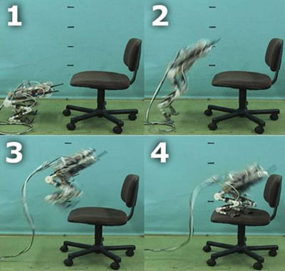
- Starting reading papers about birds and what happens during take-off, a 7g jumping robot, a jumping/gliding robot
- Also learned a lot from John about surface mount soldering with solder paste and an adhesive-backed mylar stencil, capacitive sensors, silver lycra (possibly sputtered; lessemf.com), Nitinol (light, conductive, superelastic, expensive), and much more
- To do: sparkfun tutorial for eagle
June 17
Existing Jumping Robots:Kovač, Mirko, Manuel Schlegel, Jean-Christophe Zufferey, and Dario Floreano. "Steerable miniature jumping robot." Autonomous Robots (December 2009).
- Precision Urban Hopper (https://share.sandia.gov/news/resources/news_releases/sandia-hopping-robots-to-bolster-troop-capabilities/)


- Jumping robot with deformable body (http://www.ritsumei.ac.jp/se/~hirai/research/softrobot-e.html)
- Deformable body jumping robot (http://www.ritsumei.ac.jp/se/~hirai/research/softrobot-e.html):
- 400g + mass of jumping mechanism
- ~2 foot jump height?
- Spring, piston, combustion, rubberband...?
- energy storage, actuation, power, control
- quick energy release
- light-weight reloading mechanism (ie probably not a compressor)
June 21
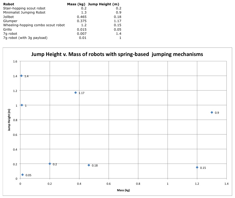
- Read up on more jumping mechanisms and robots and plotted Jump Height vs Mass of robots with spring-based jumping mechanisms. As Alexis noted, it seems like it's possible to get robots with masses up to at least 1.3kg to jump about 1 m, which makes me think getting our glider to jump is feasible...
-
- Started to relearn Solidworks in the process of modifying the CAD files for a test rig that will be used to test potential new adhesives for StickyBot
- Learned about CA hinge. It absorbs CA really well so it's often used for ailerons on RC planes
June 22
- Continued researching jumping robots and jumping mechanics (including that of kangaroos, which can store up to 70% of their energy on landing for reuse!)
- Interesting finds:
- Braided pneumatic actuators (see Design_of_a_cricket_microrobot.pdf)
- One-way bearings (http://www.rctek.com/technical/bearings/bearings_one_way.html) used in Wheeling-hopping Combination Scout Robot (see JumpingDesign) and in two-speed transmissions (http://www.rctek.com/technical/transmission/two_speed_tranny_design.html)
- Started SDM process with Alexis, Ben, and Zhi to manufacture new spines:
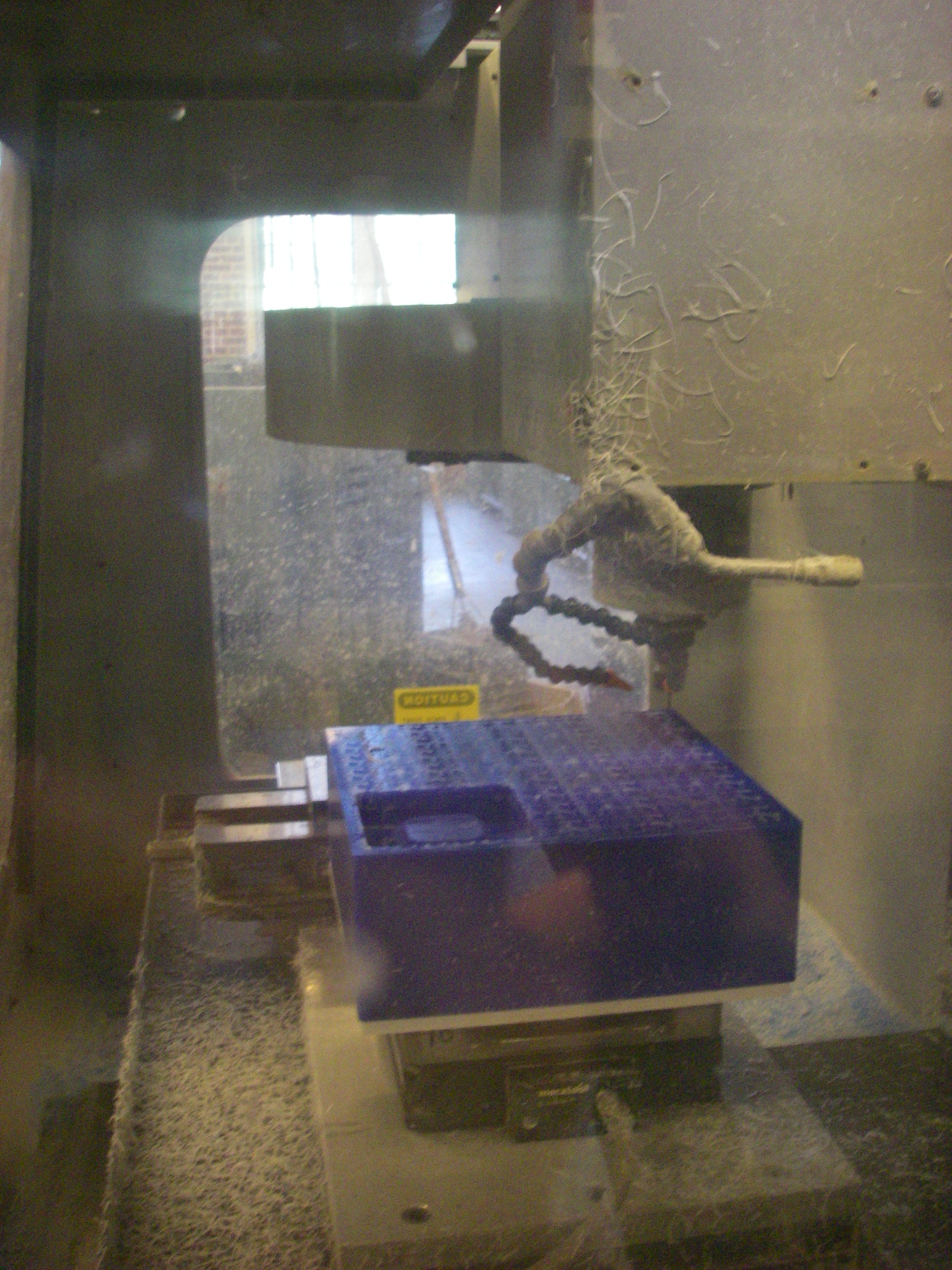
- CNCed the molds in a wax block in the PRL, then relocated to the Learning Fabrication Lab (LFL) for the rest of the process
-
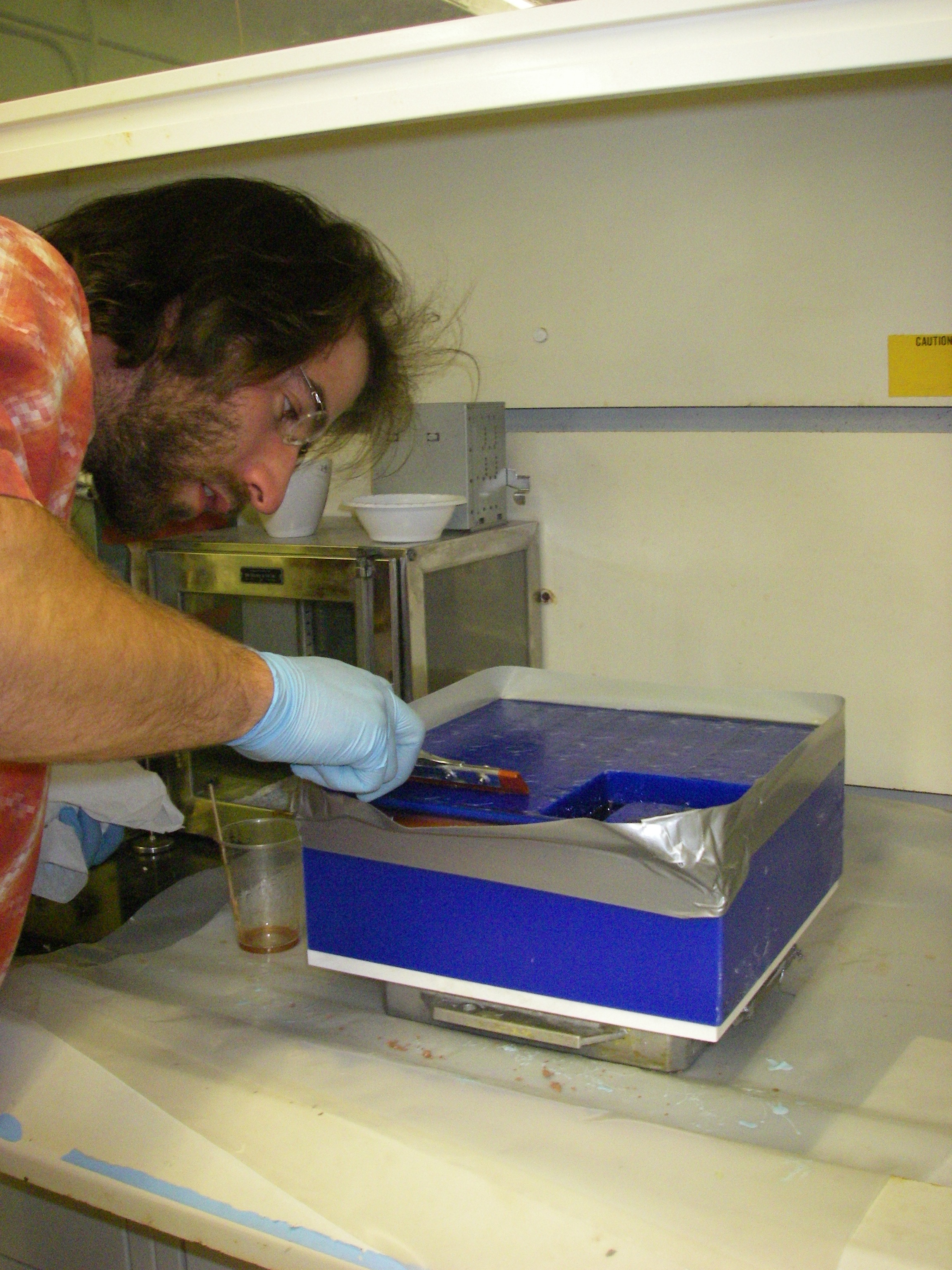
- oh-so-carefully placed the fish hooks into the mold
- added duct tape walls around the edge of the wax block so the Task 9 wouldn't drip down the sides
- mixed Task 9 at a ratio of 115:100 by weight of PartA:PartB (and contemplated the consequences of drinking the milky substance)
- placed the mold into a vacuum to remove the air bubbles
- left mold in the fumehood to let set overnight
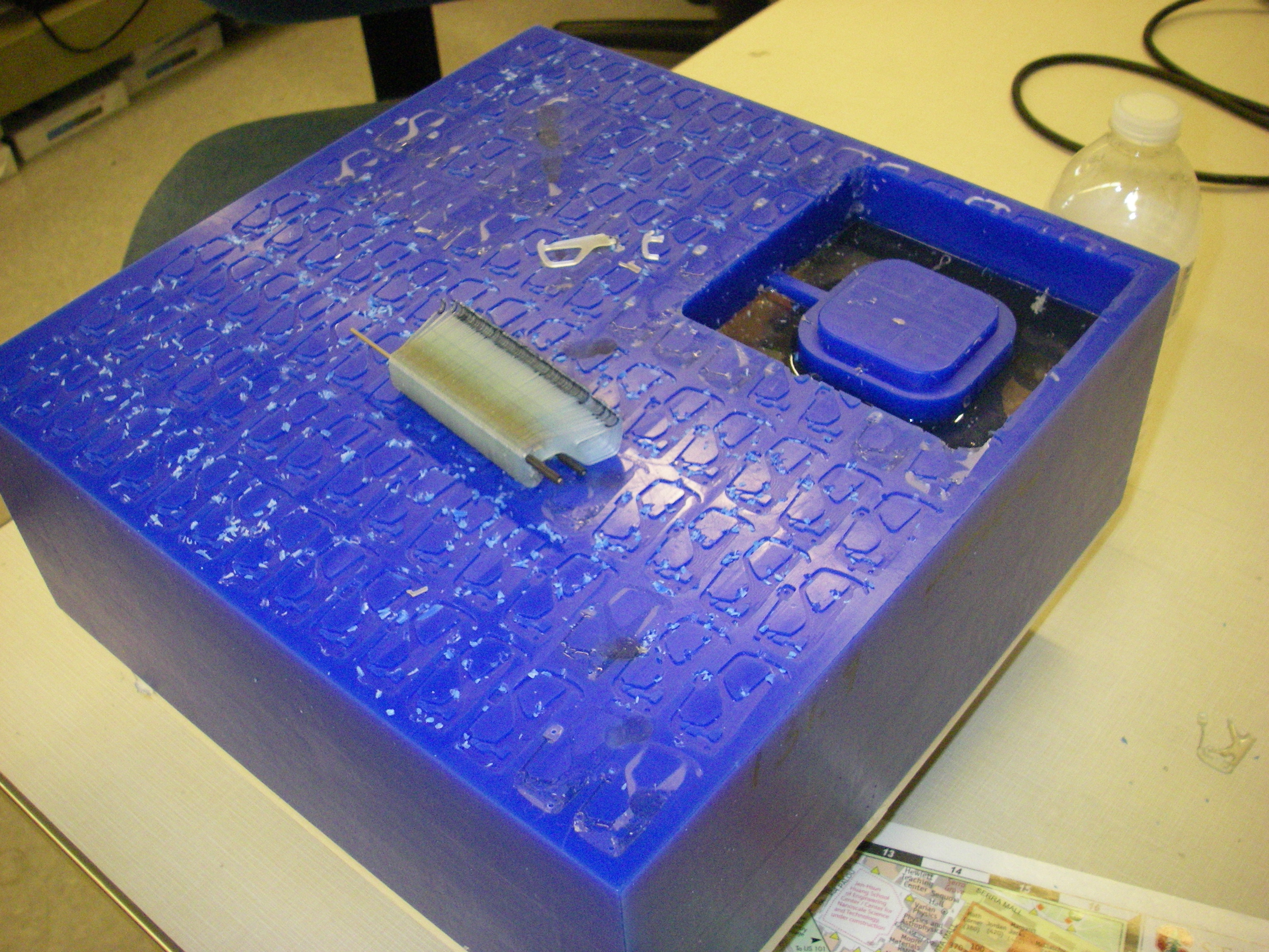
- The next morning...
- IMGP4960.JPG:
- IMGP4960.JPG:
June 23
- Today was great. I got to do/see a fair bit of hands-on activity, which was quite fun.
- We continued the SDM process and the Vytaflex 20 is setting in the mold (it takes 16 hours to set)
- CNC-ed off the layer of excess Task9, an additional .1mm layer, and removed the wax where the Vytaflex is supposed to go
- Mixed Vytaflex 20 urethane rubber (1:1 weight ratio of PartA:PartB) and poured the coke-syrup-looking mix into the mold. Normally Vytaflex 30 is used for the spines, but the lab ran out. Alexis scraping of excess Vytaflex:
-
- We were going to use Vytaflex 40 (which is less stretchy than Vytaflex 30), but one of the substances turned out to be crystalized, prompting a discussion about nitrogen gas blanketing. It's awesome to learn about all these different processes, techniques and materials!
- Ben has been working on the test rig for stickybot, so I went to the LFL with him to get more familiar with the LaserCamm. As always, very cool.
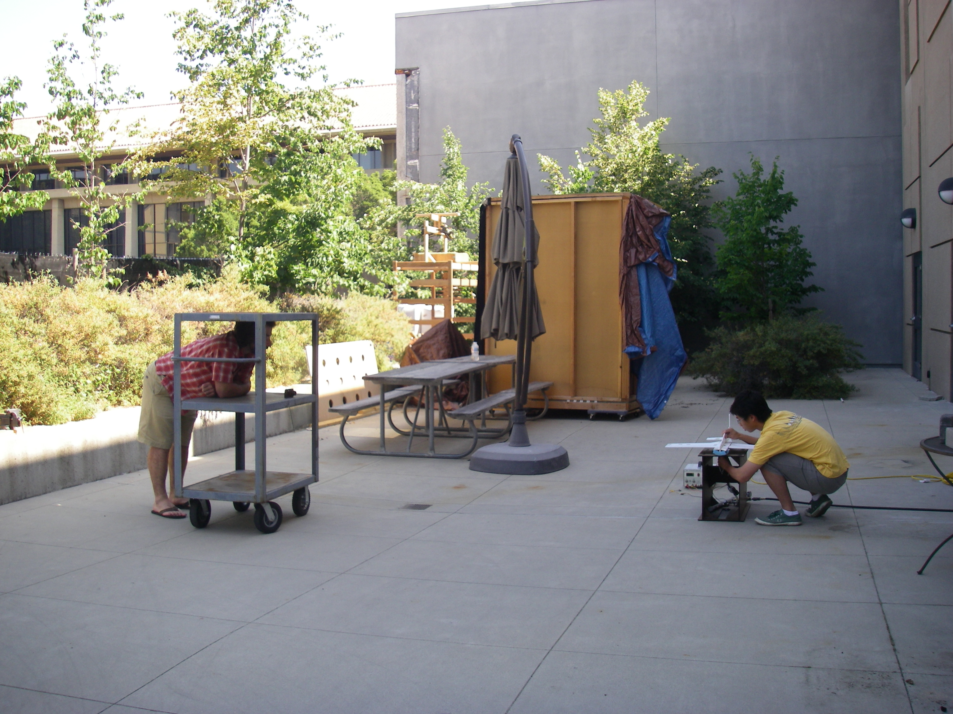
- Zhi and I also started using his test launcher to experiment with launch angles and velocity. We performed three launches at 80psi and launch angles starting at 40 degrees up, increasing by 10 degrees, and ending with 80 degrees (rel to horizontal). As always it took longer than one would expect. Glider first aid took place on (more than) a few occasions, but we ended up with a good mix of successful launch videos and amusing launch videos.
- I also learned about constant-force springs...!
June 24
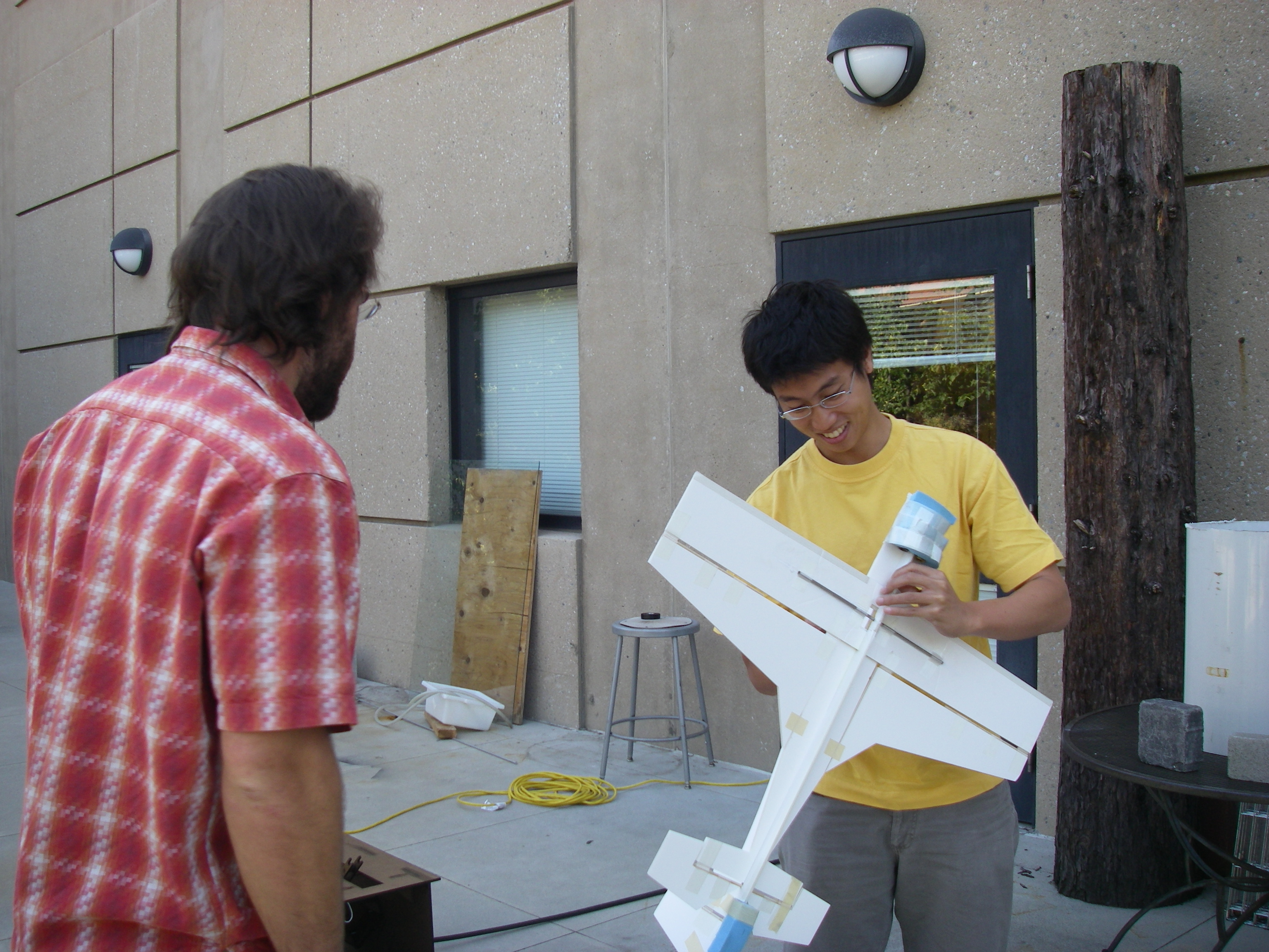
- Zhi and I continued testing with his launcher today. As the Alexis/Zhi's simulation predicts, things go wonky at 80 degrees (and things break....). The glider quickly pitches up and crashes pretty hard on its tail. Since we started with 80 degrees, we decided to move on to 70 degrees after one launch at 80 psi. For all the other launch angles (70,60, 50, and 40), we performed two launches at 30, 40, 50, 60, and 70 psi (for some reason we stopped doing 80psi). It took us some time to get started (read: reinforce the glider with even more rods, carbon strips, super glue, foam and tape), and the glider has put on more than a couple grams (it has a total mass of 480 grams), but it was mostly smooth flying for the rest of the morning.
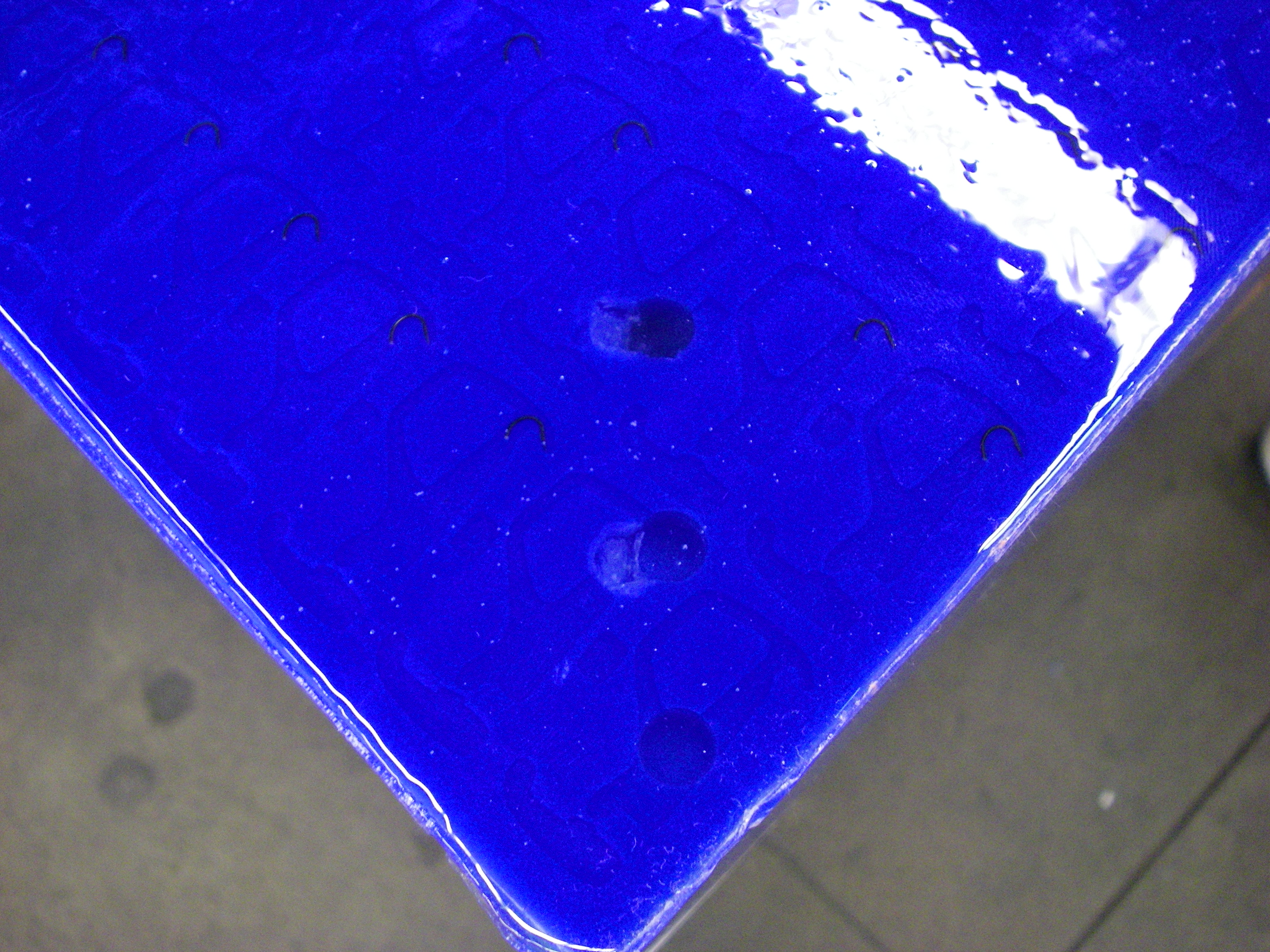
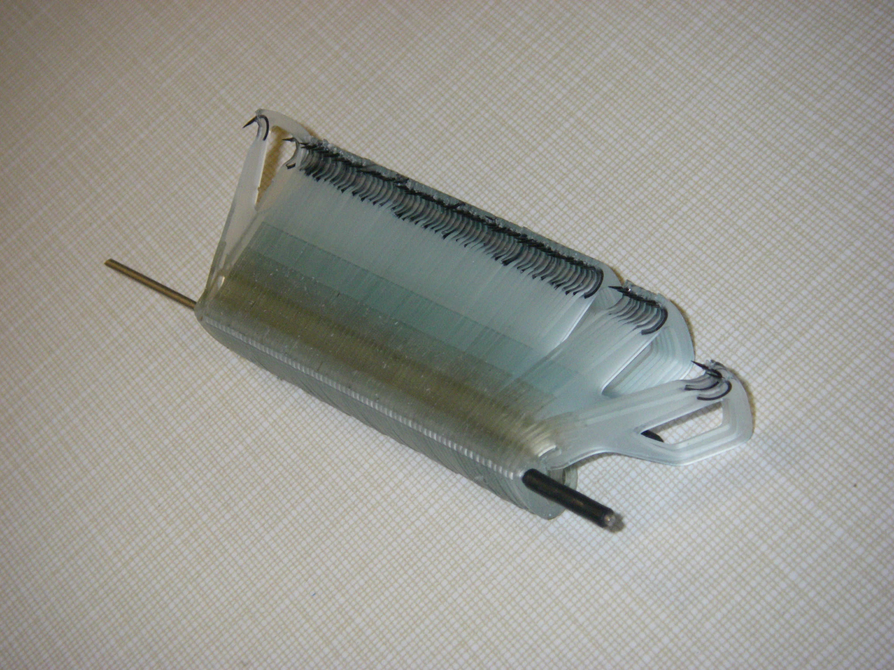
- Post lunch: spine-removal! We removed the completed spines from the wax block and clean off the excess Vytaflex and lingering wax. There are so many different materials you can use depending on the desired properties of your end product. Vytaflex and Task9 are of the thermosetting class of materials -- you mix two substances together and they chemically react and harden.
- The finished product!
-
- Zhi, Alexis, and I had a chance to talk about what we've done so far and next steps. From looking at all the jumping robots that currently exist and the videos of the tests with the launcher, it seems that a jumping mechanism for the plane is feasible. The plan is to run Alexis's MatLab script tomorrow to do more rigorous analysis of the plane at different launch angles and psi... We brainstormed functions, so that now we can start to attach numbers to functions (ex max/min mass) and think about possible designs. Meanwhile, Zhi is going to build a plane to test on the launcher to see if we can get something flying. I'm getting a better idea of what I'll be doing for the rest of the summer, and I'm pretty excited!
June 25
June 28
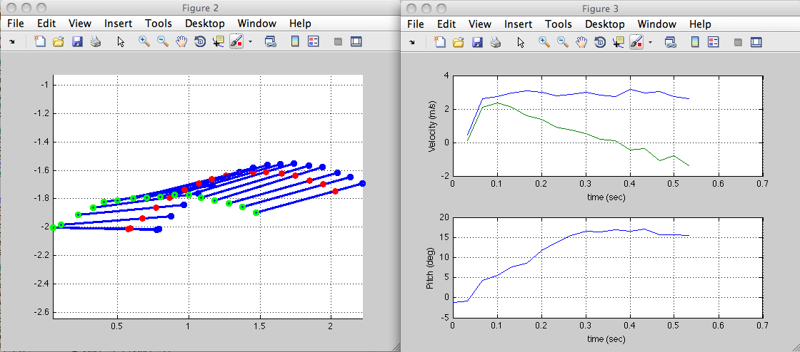
- Now that I have Matlab installed on my computer, I was able to process the videos of all our launch tests. Using Alexis script, I went through frame by frame of each launch, selecting the nose and tail of the plane. It was definitely tedious, but the product was always satisfying. The graphs of our trajectories all look pretty good, and Alexis script also allows us to graph the pitch of the plane and it's horizontal and vertical velocities. Here are the graphs for 80degrees at 80psi. The left graph is the trajectory (green is the tail, red is the center of mass, red is the nose) and the right graphs are velocity (blue is horizontal velocity and green is vertical velocity) and pitch of the plane:
June 29
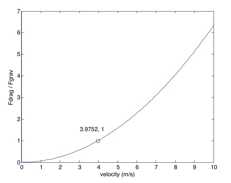
- More Matlab today! I graphed drag force over weight of the airplane at velocities between 0 to 10, using Fdrag = .5*(drag coeff)*rho*Area*v^2 where drag coeff = sin(alpha)^2 at alpha = 90. As illustrated below, when velocity is around 4 m/s, Fdrag becomes more significant than the force of gravity.
-
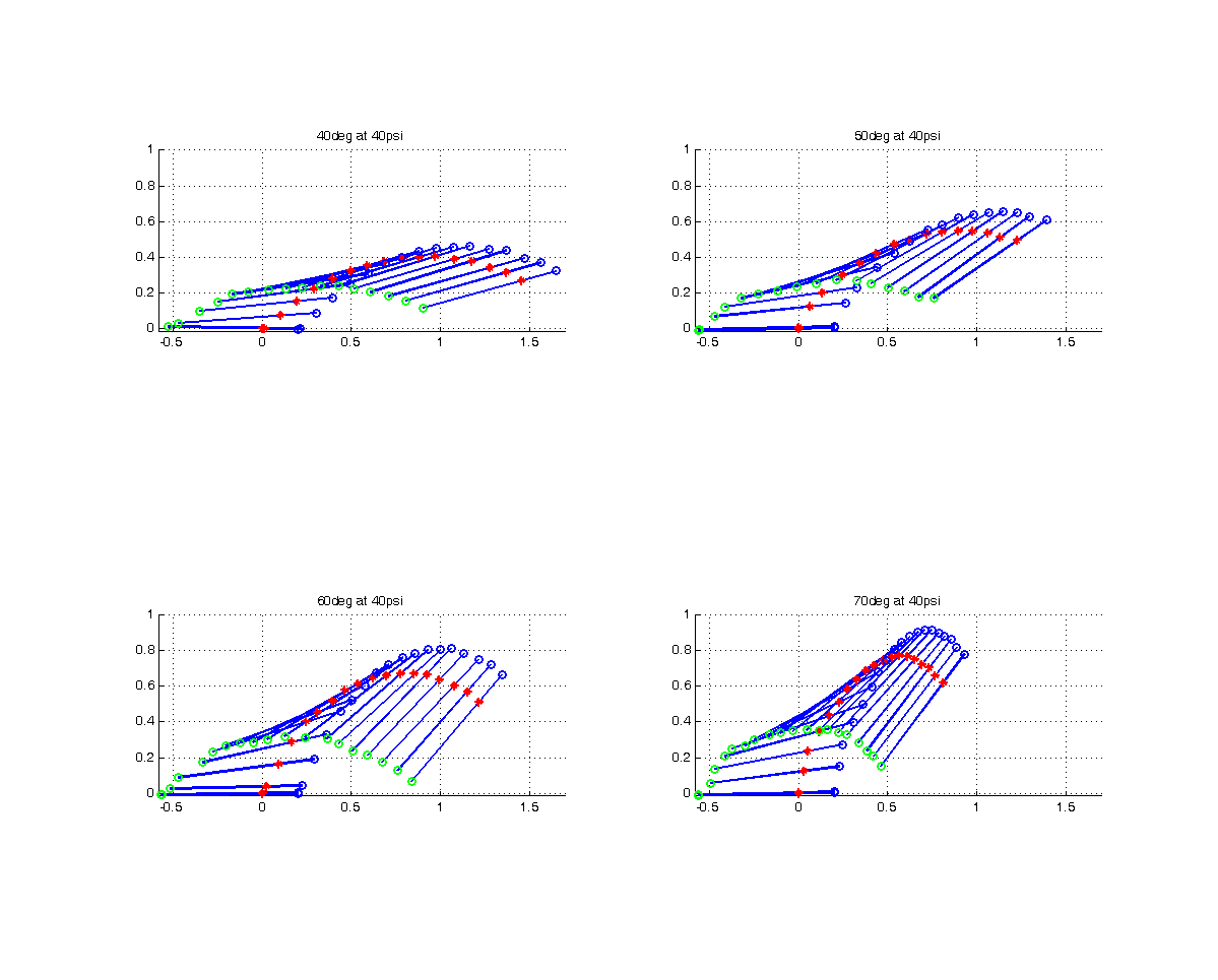
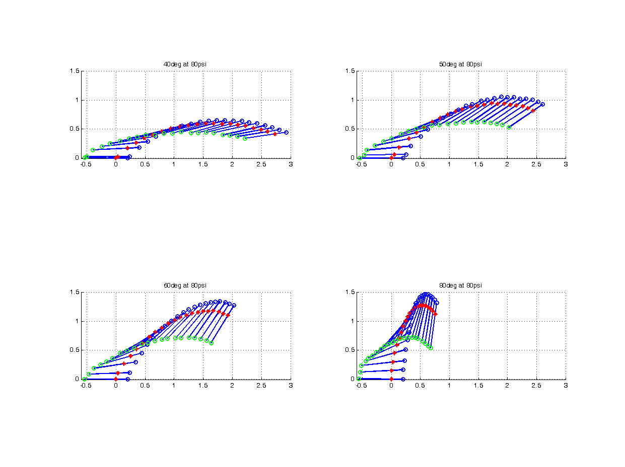
- On a more exciting note, I cleaned up the graphs paths of the glider from our launch tests, enabling us to easily compare pitch angles at 40psi and 80psi. It's really interesting to hear what Alexis concludes from the graphs. For example, the white space under the curve where there are no colored dots is the area that all parts of the plane clear. That's really obvious, but I don't know what to look for yet.
-
-
- Rewinding to the beginning of today, two phd students from Seoul National University presented their research and other projects in their respective labs. One student is working on a underwater robot that's intended to remove starfish from oyster farms. Apparently starfish are major pests at oyster farms (of which there are apparently many in Korea). Currently, women dive down and remove them by hand, and a robot would be cheaper(?) and avoid health risks for the divers. Another project that was interesting (and amusing) was a biomimetic flytrap based on a bistable structure. It looked just like a venus flytrap...cool!
- After spending so much time working in Matlab, I really wanted to build something, so I dug through the cabinets for gears and rods that would allow me to put together something similar to frogbot (see "Minimalist Jumping Robot for Celestial Exploration"). Nothing was really fitting nicely, though, and I realized I could build something at home in 5 minutes with Lego Technics, so I decided to just wait until later to build something.
- For the rest of the day, I worked with Ben to assemble all the LaserCamm-ed parts for the Stickybot test rigs. It was a lot of countersinking holes with the drill press and gluing and screwing parts together, so it was actually really fun.
June 30
- In the morning I completed the spring-based jumping mechanism that I started putting together last night. It doesn't jump well at all, but it was fun to put together and it's fun to play with.
- I also did a few rough calculations today to determine the range of energy we need to store in order to attain the behavior we observed in launcher testing. It's exciting to use the data we collected to do concrete calculations. It's a really simple energy calculation with a few assumptions.
- The lower and upper bounds for energy storage correspond to 40psi and 80psi at 40deg launch angle. Achieving 40psi behavior with a jumping mechanism is more realistic, but we're set if we are in fact able to get up to 80psi behavior because at that point it's basically gliding.
- For 40 and 80psi, I looked up initial Vx and Vy from our data, found Vtotal, and calculated KE=.5mv^2 at launch (assuming mass = .5kg).
- The results: 5.08 Joules to 13.14 Joules of energy storage, assuming 100% energy efficiency and a jumping height of .5 meter. 70% efficiency is achieved by frogbot), which corresponds to 7.26 to 18.77 joules.
- This, of course, also assumes no air drag force during take off...
July 1
- I started the day out thinking about possible designs tto perform the different functions we decided are important. More notably, Ben and I finished up the test rigs for stickybot. Ben's going to put together a info sheet that I'll add the packages tomorrow, otherwise 3 of them are ready to addressed and shipped! The 4th rig needs to wait until Mark get's back, so we can take the pad off the foot on the rig that Mark has with him and put it on this final test rig. We went through a couple of iterations, but I think we're pretty close to perfecting the art of making test rigs for Stickybot...
- We also started making more spines for Ben's opposed spine gripper (currently waiting for the Task9 to set).
July 2
- Awesome end to the week!
- Brainstormed jumping mechanisms with Alexis, John, Alan, and Zhi
- Got an intro to flying RC planes
July 3/4
- Mark came back from Europe with improvements to the Stickybot test rigs, so I've been updating the Solidworks model to improve the robustness of the testers. dxf files are finally ready to "print" on the lasercamm tomorrow!
July 12
Talked with Alexis a bit today about the landing tests he's performing to validate the results of his simulation. A lot of interesting stuff. One small thing he said that makes a lot of sense but is cool to hear articulated is that the pivot point moves the more you bend a compliant beam. Also, the memory foam he's using for damping is awesome because its damping force varies with impact velocity (it reminded me of oobleck, or cornstarch and water).July 14
We ran out of adhesive pads for the demonstrator rigs, so Elliot helped us make make more pads today! We mixed Syl (1:1 by weight, so we used 10g of each) and poured it on 2 glass slides, which we spun at 1000rpm for 60seconds to create just a thin layer of Syl on the glass slides. Then we dipped the tips of the wedges (not micro) and placed them on top of the sheet of microwedges. After curing in the oven for 15 minutes, the new Syl now binds the microwedge layer to the larger wedges. We used Sylpoxy to then glue the layered wedges to a plastic slide which we then superglued to the carbon strips on the test rig feet! Talked with Elliot about different ways they're trying to make new microwedges because only 1 of the 20 molds made still work, and the guy who made them using SU-8 and UV exposure(?) is no longer at Stanford. One method they're exploring is using small nylon microbeads, melting them and pulling up to form microwedges. The idea of pulling up is a neat idea because theoretically the radius of the bead in it's "stretched"/"extruded" state decreases to form a wedge/cone shape. They're still experimenting with different methods and materials, so a few relevant questions are: What temperature? How do you stick the beads to two surfaces in order to stretch the beads but then release the bead from one surface (what kind of material) after stretching is completed? How do you heat up the bead appropriately/uniformly? (Apparently another lab tried a technique similar to this, but they never published anything on their techniques or results...). Other possibilities are making different shapes at the end of the microwedges. One method used was to somewhat flatten the wedges (by just pressing on a flat surface) and forming a tiny puddle of material at the tip of each compressed wedge (which has to be spaced decently far apart from other wedges to avoid the puddles merging into one). Once cured, you get something like a suction cup shape at the end of the microwedge, and it's at an angle relative to the large wedge because all the wedges were slightly flattened throughtout the process. In the meantime, supposedly Draper's having some succuss making molds from microwedges...?July 5-15
I clearly got sidetracked from blogging the past two weeks, but had I blogged, I would have talked a lot about solidworks, lasercamming, ABS, CA hinge, superglue, 0-80 and 3-48 socket screws... Anyway, after numerous iterations, the testing rigs for Stickybot are finally done! We mailed them off this morning to various people/labs so they can firsthand experience the awesomeness of stickybot's adhesive pads. As is always the case with these kinds of projects, redesigning the foot over the course of many cycles of lasercutting/solidworks/testing/breaking took much longer than one would expect. I got some good experience with configurations in Solidworks and using Corel and the laser cutter to cut and rastorize ABS, masonite, and CA hinge. I had fun making boxes to hold the feet during shipping (maybe overkill? but totally worth it on many fronts. Some even have embedded magnets to hold them shut), and there are so many more things I want to make using the lasercamm now! It's still not perfect (nothing ever is), and there are things I would change if I were to make improvements, but I think the current foot design is pretty solid right now. And Ben and I can churn them out no problem -- we made 6 more today to send to Draper Labs (with spare parts for 5 more already cut). We went through quite a few iterations and it wasn't great fun to redesign and rebuild the rigs and feet that were all packed and ready to mail off 2 weeks ago, but for the most part I really did enjoy assembling everything -- it's pretty much like playing with LEGOs... In other news, I've fallen a little behind on making planes jump. Excited to start thinking about jumping mechanisms again or, rather, I'm excited to start building jumping mechanism...July 16
So, what happens when the feasibility of a design becomes too hard to analyze rigorously using calculations and models? Prototyping time! I spent a lot of time today trying to figure out the best way to start evaluating some of designs we came up with during the brainstorming session two weeks ago. It was hard to make much headway, because even if the force and velocity profiles over time can be determined, we don't know what is optimal. The authors of the "Minimalist Jumping Robot For Celestial Exploration" paper used a 6 bar linkage for their jumping mechanism which they argue optimizies Power = Force*velocity. The 6 bar linkage initial force and velocity are small, and velocity increases at a slower rate than compared to a linear spring, which help to avoid premature take off. In the event of a takeoff before a spring has contracted entirely/fully transferred its stored energy, the amount of energy lost is minimized by the fact that force drops off steeply after peaking. Is this really the case? Also, it's hard to predict the efficiency of a system (the percent of energy stored that actually gets converted to kinetic energy). I decided to ask Alexis for advice, which always makes for a more productive day - thanks, Alexis! Plan of action? Over the next 2 weeks, come up with designs for a couple ideas, order parts, and start playing... Here are the 5 designs we're considering at the moment:- 1) 6 bar linkage
- 2) Elastic jumping foot. Material-wise, Alexis suggested trying layers of carbon fiber glued together with epoxy. One possible way to implement this idea would be to have a flat straight carbon fiber "foot" that points straight down from the plane (or at some other angle) and flex that up toward the nose of the plane and lock it in place with a rope (or something). Then cut that rope... The thought is initially there'll be a large contact area between the foot and the ground, so force would start out high (and decrease thereafter) and velocity would increase pretty quickly (faster than the 6bar linkage)
- 3) Rocket engines
- 4) Conical balloon, with the tip pointing to the ground. This setup would also give a large initial force, and increasing force and velocity, since as you add more air (can we inflate it fast enough for this to work?) the radius of the contact area with the ground decreases. Where does one find a conical balloon?
- 5) 4 bar linkage with a cam loaded spring (as was used in the 7 gram robot)
July 19-20
I put together a mcmaster order of supplies to buy to prototype ideas for jumping mechanisms. To get a sense of what range of spring constants we'll need for the 6 bar linkage, I spent some time characterizing some of the springs we have in lab. Mcmaster specs also specify what the maximum stretch of the spring, which I used to calculate the upperbound on energy storage to ensure the minimum energy requirements are met. I ended up choosing a 6.5" long spring with a spring constant of 6.5 pounds per inch (or 970 N per meter). Storing 5.18 J of energy corresponds to a displacement of 4.07", which seems to be pretty large especially no top of an initial length of 6.5" inches, but it seems worthwhile to try. I also bought some torsion springs to build something similar to the 7g robot 4 bar linkage and thicker strips of carbon fiber for the elastic foot idea.July 21
Placed another order today, this time with Tower Hobbies. After talking with folks in the lab about rockets and rocket motors (on rockets and other large objects like christmas trees...), I modified John's tree launching code to create a simplified models of the airplane's behavior with B6-0, C6-0, and D12-0 booster engines attached. The code takes points on an engines thrust vs. time curve and uses that in conjunction with a formula for drag as a function of velocity function of drag and an ode solver to calculate position and velocity over time. The model is simplified in that we assume the orientation of the plane stays vertical. Among other things, this assumption allows us assume constant area used in the drag force calculation. Assuming no angular velocity is more valid for shorter durations of thrust (applied by the motor). Conveniently, as it turns out the B booster engines (no ejection charge) apply the same max thrust as the D booster engines but they die out faster. One B engine will launch the plane to an estimated height of about 1 meter, so I ordered a few more than that and threw in a couple D motors for good measure...July 22
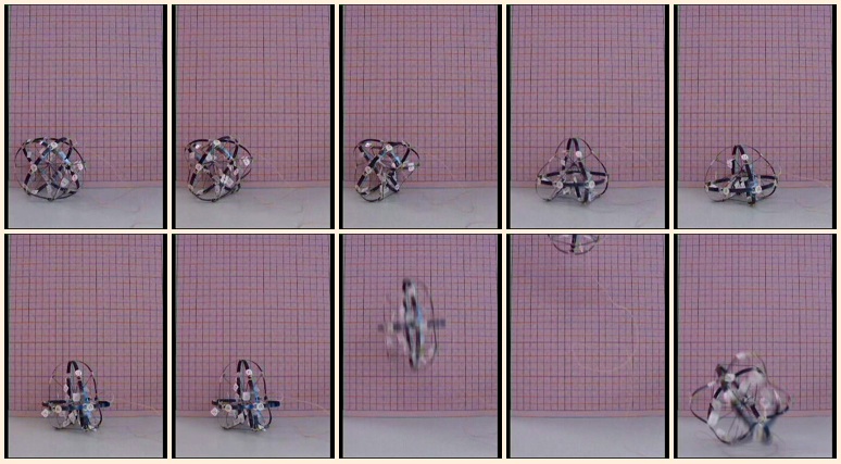
I put together a prototype jumper for the spring-y foot design, and we took a few high speed videos of it jumping today. Lots of fun! The 1/16" carbon fiber strips are way thicker/stiffer than the 1/32" thick strips, so I ended up using two 1/32" strips for starters. I was surprised by the height the jump, because I expected the mass at the top of the "foot" to just flop down and hit the ground really hard. Next steps are testing the foot with the stiffer carbon strips, running some tests to analyze the profile of the contact force between the ground and the jumper, experimenting with different orientations of the foot, and prototyping the other jumpers. In the afternoon, Ben, Marcus, Karen, and I went to Costco to buy food for tomorrows BBQ!July 23
The undergrads in the BDML woke up at the crack of drawn to start preparing food for MERL's BBQ. We made Teriyaki and regular burgers from scratch and had all sorts of other delicious items. After lab meeting, I talked with Alexis about jumping, and he's going to introduce me to Working Model 2D next week. I also learned about oscillators from Samson and then got to talk for a bit with Karlin who stopped by to visit and help out with a haptics project!July 26
I prototyped the 5 bar linkage mechanism today using the spring (k=5.54 pounds/in) I ordered from mcmaster. The prototype is from wood so it's on the heavy side. Next time I definitely want to make it lighter. Without any extra weight, the jumper seemed to jump not more than a foot off the ground, but adding weight at the top of the jumper increased the ratio of total mass to the mass of the foot and the jumper jumped noticeably higher (adding mass to make something jump higher is definitely not intuitive). I want to take videos of a series of jumps on top of the force plate for this mechanism and the carbon fiber springfoot jumper, too, sometime in the next few days. I also had an interesting conversation with Mark, and he showed me a really neat book called Materials Selection in Mechanical Design by Michael F Ashby. Elastomers store more energy per unit weight than metal (like metal springs), so I plan on buying rubberbands (or something similar) to also test on the 5bar linkage.July 27
I spent a lot of time playing around with Working Model 2D today. I now have a model of the 5bar linkage that I've gotten it to jump, so I've started to look at position graphs and force profiles. There isn't a force graphing feature built into the program as far as I can tell, but John suggested I mount the launching platform on a spring with a pretty large spring constant (so the motion of the platform doesn't exceed the 1-2% of the increase in height of the mechanism itself as it "unfolds"). I'm getting some weird results -- the change in height of the platform is initially linear and sometimes its height increases at the very beginning of the jump (which makes no sense). Hopefully jumping the prototype on a force sensor will shed insight on this.July 28
The 5bar linkage mechanism broke today when I tried replacing the metal spring with rubber bands (so much lighter!), so I'm making a new one in addition to repairing the old one. Hopefully the new one will be lighter, and I'm pretty sure it'll be stronger (balsa and carbon fiber...). Mark suggested Latex as a good elastomer to experiment with, so I ordered some surgical tubing to test on the new mechanism. I also started playing with the 4 bar linkage and torsion spring design, but I realized it's pretty similar concept to the carbon fiber jumper that I made, so it might not be worth spending too much time on it...July 29
Test day! Zhi and I successfully blocked off outside access to lab this morning by hanging a giant net that we then flew planes into. The goal was to test the feasibility of jumping takeoffs using Zhi's launcher and a plane Zhi made. I'm don't know what the motor specs are, but the plane seemed to be flying when we put it at half throttle and jumped it at 40 degrees and 40 psi. Next steps are to narrow down minimum specs necessary for achieve flight.Ideas, requests, problems regarding TWiki? Send feedback